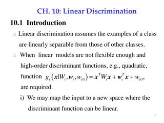
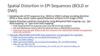
Introduction to Technology Mapping Using Linear Delay Model
Explore the process of technology mapping on a Directed Acyclic Graph (DAG) using a linear delay model. Learn about transforming circuits into subject graphs, utilizing sample cell libraries, and implementing circuits to meet user requirements. The challenges of technology mapping, circuit recovery, and dynamic programming are covered, enhancing your understanding of linear delay models and circuit design optimization.

Download Presentation

Please find below an Image/Link to download the presentation.
The content on the website is provided AS IS for your information and personal use only. It may not be sold, licensed, or shared on other websites without obtaining consent from the author. Download presentation by click this link. If you encounter any issues during the download, it is possible that the publisher has removed the file from their server.
E N D
Presentation Transcript
Sz-Cheng Huang ALCom lab, GIEE, NTU Jan 24, 2008
Introduction to technology mapping Technology mapping on a DAG using a linear delay model Linear delay model The difficulty Technology mapping starting by splitting a DAG into trees 2
Introduction to technology mapping Technology mapping on a DAG using a linear delay model Linear delay model The difficulty Technology mapping starting by splitting a DAG into trees 3
Circuit C17 Input : A circuit transformed into a subject graph A library consisting of many gates 4
Corresponding subject graph in which each node is a predifined universal gate Input : A circuit transformed into a subject graph A library consisting of many gates 5
A sample cell library Input : A circuit transformed into a subject graph A library consisting of many gates 6
An implementation Output : An implementation of the circuit constructed by gates in the library Such implementation satisfies the user s need 7
Dynamic programming Prepare library gates for each node Recover a circuit implementation C C A A D D B B E E 8
Introduction to technology mapping Technology mapping on a DAG using a linear delay model Linear delay model The difficulty Technology mapping starting by splitting a DAG into trees 9
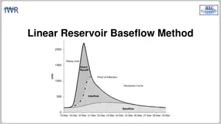
Linear delay model : Delay = block delay + fanout delay = block delay + fanout delay per load * fanout load Delay 2+3+2*Load l o 3+2*Load N m p Load 10
Introduction to technology mapping Technology mapping on a DAG using a linear delay model Linear delay model The difficulty Technology mapping starting by splitting a DAG into trees 11
The diffuculty in preparing library gates for each node Prepare for all possible fanout loads gate NAND2 is best for load L1 gate AND2 is best for load L2 There may be many possible fanout loads D A E C B F 12
Prepare library gates for each node Delay X Load 13
Prepare library gates for each node Delay X Load 14
Prepare library gates for each node Delay X Load L1 L2 15
Another difficulty happens on a DAG The delay of fanins is no longer clear C C A A D D B B E E 16
Introduction to technology mapping Technology mapping on a DAG using a linear delay model Linear delay model The difficulty Technology mapping starting by splitting a DAG into trees 17
Perform technology mapping on every subtree Implemented in SIS 18
Effectively reduce delay Area increases impressively as well as runtime Delay typical split Area typical split C17 5 5 C17 14 18 C432 119.8 42.2 C432 563 583714 C499 77.4 31.8 C499 864 736352 C880 67 29.4 C880 736 15494 C1908 117.3 45.8 C1908 1002 1522094 C2670 99.5 29.8 C2670 1465 50204 C5315 145.3 57.1 C5315 3784 2505756 C7552 264 47.4 C7552 4838 1442838 20
To prevent too much increase on area There must be may equivalent nodes caused by split! Pre-merge Selectively merge equivalent nodes before technology mapping Reduce both area and runtime More equivalent nodes Sub-optimum delay may be derived Post-merge Selectively merge equivalent nodes after technology mapping Reduce only area Fewer equivalent nodes Preserve optimum delay achieved 21
Split a DAG into trees provides a near lower bound on delay Split is better than partition in terms of linear delay model Split is more flexible because it explores more solution space than partition does Merging equivalent nodes, no matter in Pre-merge or Post-merge, is important to reduce area and runtime overhead 22
Thank you! 23