Understanding Wedge Failures in Geotechnical Engineering

Wedge failures in geotechnical engineering occur when slopes with discontinuities experience sliding along the line of intersection of two planes. This type of failure can happen under various geological and geometric conditions and involves specific criteria such as the dip of the intersecting planes and the direction of sliding feasibility. By analyzing wedge failures, engineers can assess factors of safety and design measures to mitigate risks in slope stability.

Download Presentation

Please find below an Image/Link to download the presentation.
The content on the website is provided AS IS for your information and personal use only. It may not be sold, licensed, or shared on other websites without obtaining consent from the author. Download presentation by click this link. If you encounter any issues during the download, it is possible that the publisher has removed the file from their server.
E N D
Presentation Transcript
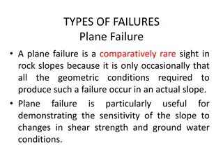
Wedge Failure It is concerned with slopes containing discontinuities striking obliquely to the slope face where sliding of a wedge of rock takes place along the line of intersection of two such planes. Wedge failures can occur over a much wider range of geologic and geometric conditions than plane failures. Figure 1 shows a typical wedge failure involving sliding on two persistent joints with line of intersection of joints day lighting at toe of rock face, and an upper plane that formed a tension crack.
Conditions There are three conditions of Wedge Failure: Two planes will always intersect in a line. The dip (plunge) of the line of intersection must be flatter than the dip of the face, and steeper than the average friction angle of the two slide planes, that is fi > i> . The line of intersection must dip in a direction out of the face for sliding to be feasible.
The dip direction (trend) i and dip (plunge) i of the line of intersection of planes A and B can be determined by using the following equations where A and B are the dip directions, and A and B are the dips of the two planes. First equation gives two solutions 180 apart; the correct value lies between A and B.
Analysis of wedge failure View of wedge looking at face showing definitionof Angle of tilt( ) and Included angle of wedge( ), and reactions on sliding planes RA and RB.
Cross-section of wedge showing resolution of wedge weight W.
The factor of safety of the wedge defined in Figures, assuming that sliding is resisted only by friction and that the friction angle is the same for both planes is given by, where RA and RB are the normal reactions provided by planes A and B and the component of the weight acting down the line of intersection is (W sin i). The forces RA and RB are found by resolving them into components normal and parallel to the direction along the line of intersection.
In order to meet the conditions for equilibrium, the normal components of the reactions are equal and the sum of the parallel components equals the component of the weight acting into the line of intersection. By solving and adding, we get
Where FSW is the factor of safety of a wedge supported by friction only, and FSP is the factor of safety of a plane failure in which the slide plane, with friction angle , dips at the same angle as the line of intersection i. K is the wedge factor that depends upon the included angle of the wedge and the angle of tilt of the wedge. Values for the wedge factor K, for a range of values of and are plotted in next Figure.


 αi and dip (plunge) ψi of")