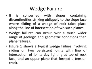
Understanding Plane Failures in Rock Slopes


TYPES OF FAILURES
Plane Failure
•
A plane failure is a
comparatively rare
sight in
rock slopes because it is only occasionally that
all the geometric conditions required to
produce such a failure occur in an actual slope.
•
Plane failure is particularly useful for
demonstrating the sensitivity of the slope to
changes in shear strength and ground water
conditions.

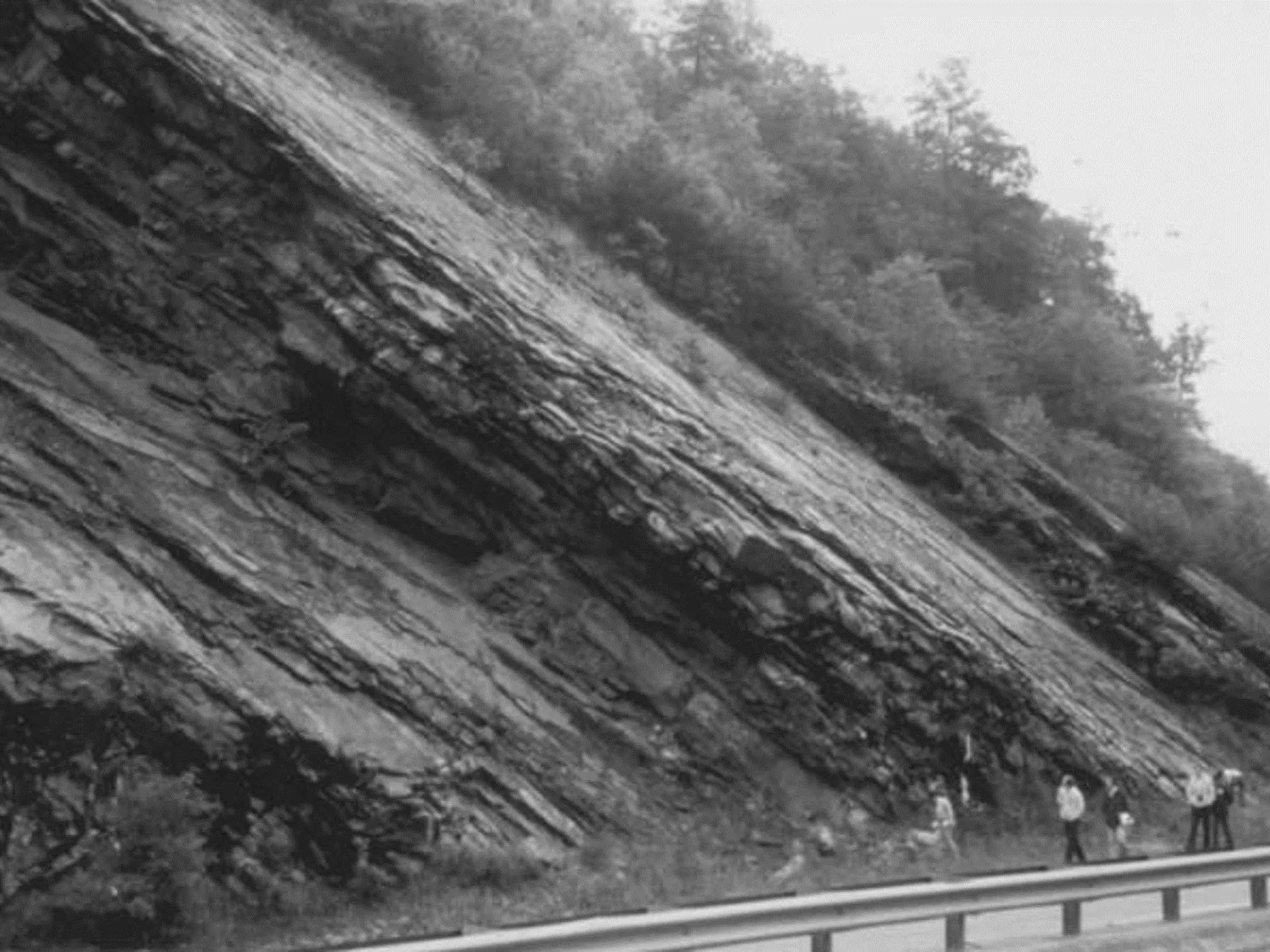
Plane failure on smooth, persistent bedding planes in shale

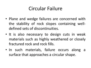
General conditions for plane failure
In order for this type of failure to occur, the following
geometrical conditions must be satisfied:
•
The plane on which sliding occurs must strike
parallel
or nearly parallel (within approximately ±20◦) to the
slope face.
•
The sliding plane must “daylight” in the slope face,
which means that the dip of the plane must be less
than the dip of the slope face, that is,
ψ
p
<ψ
f
.
•
The dip of the sliding plane must be greater than the
angle of friction of this plane, that is,
ψ
p
>φ.
•
The
upper end
of the sliding surface either intersects
the upper slope, or terminates in a tension crack.
•
Release surfaces
that provide negligible resistance to
sliding must be present in the rock mass to define the
lateral boundaries of the slide. Alternatively, failure can
occur on a sliding plane passing through the convex
“nose” of a slope.
Fig 2: Geometry of slope exhibiting plane failure:
(a) cross-section showing planes forming a plane failure
(b) release surfaces at ends of plane failure
Plane failure analysis
•
The slope geometries and ground water
conditions considered in this analysis are
defined in Figure 3, which shows two
geometries as follows:
•
(a) Slopes having a tension crack in the upper
surface; and
•
(b) Slopes with a tension crack in the face.
Tension crack in the upper slope
Tension crack in the face
Assumptions
The following assumptions are made in plane failure analysis:
•
Both sliding surface and tension crack strike parallel
to the slope.
•
The tension crack is vertical and is filled with water
to a depth z
w
.
•
Water enters the sliding surface along the base of
the tension crack and seeps along the sliding
surface, escaping at atmospheric pressure where
the sliding surface daylights in the slope face. The
pressure distributions induced by the presence of
water in the tension crack and along the sliding
surface are illustrated in Figure 4.
Fig 4 (a): Tension crack in the upper slope
Fig 4 (b): Tension crack in the face
•
The forces W (the weight of the sliding block), U (uplift
force due to water pressure on the sliding surface) and
V (force due to water pressure in the tension crack) all
act through the centroid of the sliding mass. In other
words, it is assumed that there are no moments that
would tend to cause rotation of the block, and hence
failure is by sliding only. While this assumption may not
be strictly true for actual slopes, the errors introduced
by ignoring moments are small enough to neglect.
However, in steep slopes with steeply dipping
discontinuities, the possibility of toppling failure should
be kept in mind.
•
The shear strength τ of the sliding surface is defined by
cohesion c and friction angle φ that are related by the
equation τ = c + σ tan φ.
•
It is assumed that release surfaces are present so
that there is no resistance to sliding at the lateral
boundaries of the failing rock mass (Figure 2 (b)).
•
In analyzing two-dimensional slope problems, it is
usual to consider a slice of unit thickness taken at
right angles to the slope face. This means that on
a vertical section through the slope, the area of
the sliding surface can be represented by the
length of the surface, and the volume of the
sliding block is represented by the cross-section
area of the block (Figure 5).
Fig 5: Unit thickness slide used in stability analysis
When the upper surface is horizontal (ψ
s
= 0),
the transition from one condition to another
occurs when the tension crack coincides with
the slope crest, that is when;
where z is the depth of the tension crack, H
is the slope height, ψf is the slope face angle
and ψ
p
is the dip of the sliding plane.
Safety Factor
•
The factor of safety for plane failure is calculated
by resolving all forces acting on the slope into
components parallel and normal to the sliding
plane.
•
The vector sum of the shear forces, ∑ S acting
down the plane is termed
the driving force
.
•
Total normal forces, ∑N multiplied by the tangent
of the friction angle φ, plus the cohesive force is
termed as
resisting force
.
•
The factor of safety of the sliding block is the
ratio of the resisting forces to the driving forces,
and is calculated as follows:
Where c is the cohesion and A is the area of the
sliding plane.The factor of safety for the slope
configurations shown in Figure 4 is given by,
where A is given by,
The slope height is ‘H’, the tension crack depth is
‘z’ and it is located a distance ‘b’ behind the slope
crest. The dip of the slope above the crest is ‘ψ
s
’.When
the depth of the water in the tension crack is ‘z
w
’, the
water forces acting on the sliding plane ‘U’ and in the
tension crack ‘V’ are given by,
where γ
w
is the unit weight of water.
The weights of the sliding block W for the two geometries
shown in Figure 4 are given by following equations. For the
tension crack in the inclined upper slope surface
(Figure 4(a)), equation (6.8) will be used. For the tension
crack in the slope face (Figure 4(b)), second equation will
be used.
where γ
r
is the unit weight of the rock.
Problem Statement
•
A 12-m high rock slope has been excavated at a
face angle of 60◦. The rock in which this cut has
been made contains persistent bedding planes
that dip at an angle of 35◦ into the excavation.
The 4.35-m deep tension crack is 4m behind the
crest, and is filled with water to a height of 3m
above the sliding surface as shown in figure 6.
The strength parameters of the sliding surface are
as follows:
•
Cohesion,
c = 25 kPa
•
Friction angle,
φ = 37◦
•
The unit weight of the rock is 26kN
/
m
3
, and
•
The
unit weight of the water is 9.81kN
/
m
3
.
Figure 6: Plane Failure Geometry
Determine the Following
(a) Calculate the factor of safety of the slope for the
conditions given in Figure 6.
(1.25)
(b) Determine the factor of safety if the tension
crack were completely filled with water due to
run-off collecting on the crest of the slope.
(1.07)
(c) Determine the factor of safety if the slope were
completely drained.
(1.54)
(d) Determine the factor of safety if the cohesion
were to be reduced to zero due to excessive
vibrations from nearby blasting operations,
assuming that the slope was still completely
drained.
(1.08)
Plane failures in rock slopes are rare but significant, indicating sensitivity to changes in shear strength and groundwater conditions. Geometrical conditions must be met for such failures to occur, including specific alignments and interactions between the sliding plane and slope face. Analysis involves considering slope geometries and ground water conditions to identify potential failure risks.

Download Presentation

Please find below an Image/Link to download the presentation.
The content on the website is provided AS IS for your information and personal use only. It may not be sold, licensed, or shared on other websites without obtaining consent from the author. Download presentation by click this link. If you encounter any issues during the download, it is possible that the publisher has removed the file from their server.
E N D
Presentation Transcript
TYPES OF FAILURES Plane Failure A plane failure is a comparatively rare sight in rock slopes because it is only occasionally that all the geometric conditions required to produce such a failure occur in an actual slope. Plane failure is particularly demonstrating the sensitivity of the slope to changes in shear strength and ground water conditions. useful for
General conditions for plane failure In order for this type of failure to occur, the following geometrical conditions must be satisfied: The plane on which sliding occurs must strike parallel or nearly parallel (within approximately 20 ) to the slope face. The sliding plane must daylight in the slope face, which means that the dip of the plane must be less than the dip of the slope face, that is, p< f. The dip of the sliding plane must be greater than the angle of friction of this plane, that is, p> . The upper end of the sliding surface either intersects the upper slope, or terminates in a tension crack. Release surfaces that provide negligible resistance to sliding must be present in the rock mass to define the lateral boundaries of the slide. Alternatively, failure can occur on a sliding plane passing through the convex nose of a slope.
Fig 2: Geometry of slope exhibiting plane failure: (a) cross-section showing planes forming a plane failure
Plane failure analysis The slope geometries and ground water conditions considered in this analysis are defined in Figure 3, which shows two geometries as follows: (a) Slopes having a tension crack in the upper surface; and (b) Slopes with a tension crack in the face.
Assumptions The following assumptions are made in plane failure analysis: Both sliding surface and tension crack strike parallel to the slope. The tension crack is vertical and is filled with water to a depth zw. Water enters the sliding surface along the base of the tension crack and seeps along the sliding surface, escaping at atmospheric pressure where the sliding surface daylights in the slope face. The pressure distributions induced by the presence of water in the tension crack and along the sliding surface are illustrated in Figure 4.
The forces W (the weight of the sliding block), U (uplift force due to water pressure on the sliding surface) and V (force due to water pressure in the tension crack) all act through the centroid of the sliding mass. In other words, it is assumed that there are no moments that would tend to cause rotation of the block, and hence failure is by sliding only. While this assumption may not be strictly true for actual slopes, the errors introduced by ignoring moments are small enough to neglect. However, in steep slopes with discontinuities, the possibility of toppling failure should be kept in mind. The shear strength of the sliding surface is defined by cohesion c and friction angle that are related by the equation = c + tan . steeply dipping
It is assumed that release surfaces are present so that there is no resistance to sliding at the lateral boundaries of the failing rock mass (Figure 2 (b)). In analyzing two-dimensional slope problems, it is usual to consider a slice of unit thickness taken at right angles to the slope face. This means that on a vertical section through the slope, the area of the sliding surface can be represented by the length of the surface, and the volume of the sliding block is represented by the cross-section area of the block (Figure 5).
When the upper surface is horizontal (s= 0), the transition from one condition to another occurs when the tension crack coincides with the slope crest, that is when; where z is the depth of the tension crack, H is the slope height, f is the slope face angle and pis the dip of the sliding plane.
Safety Factor The factor of safety for plane failure is calculated by resolving all forces acting on the slope into components parallel and normal to the sliding plane. The vector sum of the shear forces, S acting down the plane is termed the driving force. Total normal forces, N multiplied by the tangent of the friction angle , plus the cohesive force is termed as resisting force. The factor of safety of the sliding block is the ratio of the resisting forces to the driving forces, and is calculated as follows:
Where c is the cohesion and A is the area of the sliding plane.The factor of safety for the slope configurations shown in Figure 4 is given by,
where A is given by, The slope height is H , the tension crack depth is z and it is located a distance b behind the slope crest. The dip of the slope above the crest is s .When the depth of the water in the tension crack is zw , the water forces acting on the sliding plane U and in the tension crack V are given by, where w is the unit weight of water.
The weights of the sliding block W for the two geometries shown in Figure 4 are given by following equations. For the tension crack in the inclined upper slope surface (Figure 4(a)), equation (6.8) will be used. For the tension crack in the slope face (Figure 4(b)), second equation will be used. where r is the unit weight of the rock.
Problem Statement A 12-m high rock slope has been excavated at a face angle of 60 . The rock in which this cut has been made contains persistent bedding planes that dip at an angle of 35 into the excavation. The 4.35-m deep tension crack is 4m behind the crest, and is filled with water to a height of 3m above the sliding surface as shown in figure 6. The strength parameters of the sliding surface are as follows: Cohesion, c = 25 kPa Friction angle, = 37 The unit weight of the rock is 26kN/m3, and The unit weight of the water is 9.81kN/m3.
Determine the Following (a) Calculate the factor of safety of the slope for the conditions given in Figure 6. (1.25) (b) Determine the factor of safety if the tension crack were completely filled with water due to run-off collecting on the crest of the slope. (1.07) (c) Determine the factor of safety if the slope were completely drained. (1.54) (d) Determine the factor of safety if the cohesion were to be reduced to zero due to excessive vibrations from nearby blasting operations, assuming that the slope was still completely drained. (1.08)


 release surfaces at ends of plane failure")


: Tension crack in the upper slope")
: Tension crack in the face")
, U")


,")