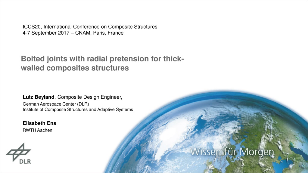
Bolted Joints with Radial Pretension for Thick-Walled Composite Structures
Explore the advancements in bolted joints with radial pretension for thick-walled composite structures discussed at the ICCS20 conference. Key topics include state-of-the-art techniques, analytical approaches, FE calculations, bearing tests, and overcoming challenges in bolted joint designs. The concept of radial pretension, applications in various industries, failure modes, and solutions to improve joint stiffness are also highlighted.

Download Presentation

Please find below an Image/Link to download the presentation.
The content on the website is provided AS IS for your information and personal use only. It may not be sold, licensed, or shared on other websites without obtaining consent from the author. Download presentation by click this link. If you encounter any issues during the download, it is possible that the publisher has removed the file from their server.
E N D
Presentation Transcript
ICCS20, International Conference on Composite Structures 4-7 September 2017 CNAM, Paris, France Bolted joints with radial pretension for thick- walled composites structures Lutz Beyland, Composite Design Engineer, German Aerospace Center (DLR) Institute of Composite Structures and Adaptive Systems Elisabeth Ens RWTH Aachen
DLR.de Folie 2 > ICCS20 > Beyland > 05.09.2017 Outline State of the art bolted joints in thick walled laminates Concept of bolted joint with radial pretension Analytical approach FE-Calculation Bearing tests Conclusion and Outlook
DLR.de Slide 3 > ICCS20 > Beyland > 05.09.2017 Bolted joints for thick laminates - state of the art Fields of application for many decades multi-stage rockets for transportation of satellites connection of aircraft wing and fuselage root connection of rotor blades of wind turbines Payload adapter Ariane 5 [DIEM] Failure modes Tension Shear Out T-Bolt connection for rotor blades [HAU] Cleavage Bearing
DLR.de Slide 4 > ICCS20 > Beyland > 05.09.2017 Problems of state of the art bolted joints Big Clearance Low Stiffness, high wear P Joint stiffness and wear depend on bolt-hole clearance P Avoiding big bolt-hole clearance leads to High effort for precise drilling of borehole Need for reaming / drilling of both joint parts in one process Small / No Clearance High Stiffness, medium wear P P Radial Pretension Very high stiffness, low wear P P
DLR.de Slide 5 > ICCS20 > Beyland > 05.09.2017 Outer ring Outer ring Inner ring Inner ring Concept of radial pretension 1 - Clearance 3 - Radial Pretension 2 - No Clearance Plate with bore hole Bolt Inner ring Outer ring Clamping bush [M DLER] Clamping bush overcomes clearance and creates a radial pretension between bolt and bore hole Radial pretension by axial tightening of inner and outer ring Outer ring of clamping bush is slatted >> Diameter increase of 1 mm possible
DLR.de Slide 6 > ICCS20 > Beyland > 05.09.2017 Research topics on bolted joint with radial pretension Analytic model to describe stress state around bore hole FE model to validate mathematical model and for detailed analysis ? Bearing tests Static and fatigue strength
DLR.de Slide 7 > ICCS20 > Beyland > 05.09.2017 Analytic approach Superposition Pretension [Timoshenko] Bolt load [Zhang] ?2+?2 ?2 ?2 ?? ? ?? ??= ? ?(?, ) = ? ??= 0 ?cos ?? ???2 ?2 ?21 ?2 (?, ) = ? ?cos ?(?) = ?? ? ?? ? ???= 0 ? ???2 ?2 ?21 +?2 ?? ? (?) = ?? ? ???= 0 ?
DLR.de Slide 8 > ICCS20 > Beyland > 05.09.2017 2D FE model - setup Disk FE-Software: Ansys Workbench 18.1 Fixed support Bolt Boundary conditions Symmetry at midplane Fixed support of disk s peripheral surface Bolt load as distributed force on bolt s peripheral surface Radial pretension by thermal expansion of bolt Frictionless contact between bolt and hole Thermal expansion Bolt load Material Linear-elastic model Disk: GFRP, quasi-isotropic stiffness Bolt: Steel Symmetry
DLR.de Slide 9 > ICCS20 > Beyland > 05.09.2017 2D FE model - results Use case Radial stress Parameter Variable Value Unit Radius bore hole a 32,5 mm Outer radius disk b 800 mm Young s Modulus disk E 27 GPa Poisson's ratio disk 0,343 - Pretension pi 270 MPa Radial expansion (caused by pretension) u0 0,5 mm Bolt load p 28 kN/mm
DLR.de Slide 10 > ICCS20 > Beyland > 05.09.2017 Comparison of analytical and FE model ? = ??? ? ? = ?? Stresses at bore hole (circumferential path) radmaximum difference: 2 MPa tanmaximum difference: 5 MPa Circum- ferential path Conclusion: Analytical model is accurate for stresses at bolt hole ? = ?
DLR.de Slide 11 > ICCS20 > Beyland > 05.09.2017 Comparison of analytical and FE model ? = ??? ? ? = ?? Stresses at bore hole (radial path) radmaximum difference: 16 MPa (~7%) tanmaximum difference: 20 MPa (~17%) Radial path Conclusion: Analytical model is sufficient for stresses at whole disk ? = ?
DLR.de Slide 12 > ICCS20 > Beyland > 05.09.2017 Effect of friction on stress distribution 2D-FE Contact status Near Sliding Sticking Friction strongly influences stress distribution Coefficient of friction between bolt and hole is not well known = 0,1 = 0,5 = 0 ? ? ? Literature [Cuntze] suggests = 0,1 0,3 >>> = 0,1 chosen ? = ??? ? = ?? ? Circum- ferential path ? = ?
DLR.de Slide 13 > ICCS20 > Beyland > 05.09.2017 Effect of pretension on stress distribution 2D-FE Szenario Pretension pi [MPa] Expansion u0 [mm] Amount of pretension significantly influences both radial and tangential stress High pretension avoids clearance under bolt load >> no tangential stress peak at ? 90 Medium pretension results in minimum overall tangential and radial stresses High pretension 270 0,5 Medium pretension 135 0,25 No pretension 0 0 ? = ??? ? = ?? ? Circum- ferential path ? = ?
DLR.de Folie 14 > ICCS20 > Beyland > 05.09.2017 Bearing test setup Special 3-Point bearing test setup Laminate thickness t = 10 20 mm Maximum static load: F = 500 kN Maximum fatigue load: -50 kN < F < +200 kN Specimen GFRP [+45 / -45 / 0 / 90]5s Bore hole for fixation Bolt d = 40 mm ? Bearing failure
DLR.de Folie 15 > ICCS20 > Beyland > 05.09.2017 Clearance fit vs. radial pretension Clearance fit Clamping bush for radial pretension Radial expansion u0= 0,4 0,8 mm Clearance = 0,1 mm
DLR.de Folie 16 > ICCS20 > Beyland > 05.09.2017 Results in bearing strength ? Bearing strength ?= F bolt load at failure d hole diameter t laminate thickness Static bearing strength with radial pretension -15% compared to clearance fit Fatigue bearing strength with radial pretension +40% compared to clearance fit High pretension results in slightly higher fatigue strength ? ?
DLR.de Slide 17 > ICCS20 > Beyland > 05.09.2017 Conclusion and Outlook Outlook Detailed understanding of bearing failure with radial pretension Prediction of failure load from FE-calculation >>> failure criteria for bearing Bearing tests with different pretensions >> evaluation of optimum pretension Bearing tests with combined radial and axial pretension Conclusion Analytic model for bolted joints with radial pretension is found and validated by FE- calculation (neglecting friction and cleavage) Friction has a big impact especially on tangential stresses Radial pretension results in smooth distribution of stresses around the bore hole Bearing tests with radial pretension show an increase in fatigue strength, but a decrease in static strength
DLR.de Slide 18 > ICCS20 > Beyland > 05.09.2017 MANY THANKS FOR YOUR ATTENTION ! DO YOU HAVE ANY QUESTIONS ? Lutz Beyland, Composite Design Engineer, German Aerospace Center (DLR), Institute of Composite Structures and Adaptive Systems Lilienthalplatz 7, 38108 Braunschweig, Germany Lutz.Beyland@DLR.de
DLR.de Slide 19 > ICCS20 > Beyland > 05.09.2017 References [DIEM] Diem, H.: Tragf higkeit von Bolzenverbindungen in dickwandigen Faserverbundstrukturen; Dissertation; TU M nchen; 19.2.2007 [HAU] Hau, E.: Windkraftanlagen: Grundlagen, Technik, Einsatz, Wirtschaftlichkeit, Springer Berlin Heidelberg, ISBN 978-3-540-72150-5 [M DLER] M dler GmbH: Spanns tze COM-AS Bohrung 19 bis 100mm; http://www.maedler.de/product/1643/1621/spannsaetze-com-as-bohrung-19- bis-100mm; accessed on 30.8.2017 [TIMOSHENKO] Timoshenko, S.: Theory of Elasticity; McGraw- Hill; 1934 [ZHANG] Zhang, K.-D.; Ueng, C. E.: Stresses Around a Pin-loaded Hole in Orthotropic Plates; Journal of Composite Materials 18 (1984), No. 5, p. 432-446 [CUNTZE] CUNTZE, R.; Das Versagensmoduskonzept, ein praktikables Auslegungswerkzeug bei neuen Leichtbauwerkstoffen ; Handout, Dresdner Leichtbausymposium, 7.-9. June 2001
DLR.de Folie 20 > ICCS20 > Beyland > 05.09.2017 Anhang
DLR.de Folie 21 > ICCS20 > Beyland > 05.09.2017 L sungsraum f r segmentierte Rotorbl tter Megawind DEBRA-25 JOULE III T-bolts T-bolts Bolting in longitudinal direction Enercon E126 Metallic Metallic inserts inserts JOULE III Detachable Gamesa Innoblade Bolting in transversal direction Form-fit Indeol / CENER Force-fit Connection principle Connection tubes tubes Connection JOULE III Bolting of pieces with a large overlap Bolting of shear web Non- Detachable Single lap Welding of thermoplasts Multi lap Modular Wind Energy Single lap Bonding of thermosets Multi lap Multi lap
DLR.de Folie 22 > ICCS20 > Beyland > 05.09.2017 Wo teilen? Bolting Bonding Transportation Spar cap loads Secondary loads Big extra mass = extra cost Extra mass = dynamic loads Little space 0 0.2 0.3 0.4 0.5 0.6 0.7 0.8 1
DLR.de Folie 23 > ICCS20 > Beyland > 05.09.2017 Konzept Stegverschraubung y Tip-Stege x Tip-Gurt Wurzel-Gurt Wurzel-Stege Detail Z B z Schnitt A-A x Detail Z y x Wurzel- Gurte Tip Gurte ca. 5m Stegbuchse Wurzelsegment Schraube mit Mutter (ca. M36) Wurzel-Steg Tip-Steg B Schnitt B-B A A z y Stegbuchse Wurzelsegment Stegbuchse Tipsegment Stegbuchse Tipsegment
DLR.de Folie 24 > ICCS20 > Beyland > 05.09.2017 CAD-Modell Stegverschraubung in Nordex-Rotorblatt NR58.5 Tipsegment tipseitige Verschraubung Endkantengurt wurzelseitige Verschraubung Hauptholm Verbindungsbereich X Z Y Wurzelsegment
DLR.de Folie 25 > ICCS20 > Beyland > 05.09.2017 Segmentiertes Rotorblatt Testpyramide (10-2016) Full Scale Test Bauteil-Tests Verschraubte Holme Biegebalken Coupon-Tests Lochleibungstests Design Konzeptentwicklung Vorauslegung CAD-Modellierung
DLR.de Folie 26 > ICCS20 > Beyland > 05.09.2017 Lochleibungstests BiLo >> verklebte Probe ohne Flansch Klebstoff Spielpassung >> gesteckte Probe Spannbuchse >> verspannte Probe
DLR.de Folie 27 > ICCS20 > Beyland > 05.09.2017 Rax-Buchse Funktionsdemonstrator + Patentanmeldung