Volvo BM L90B Wheel Loader Service Repair Manual Instant Download
Please open the website below to get the complete manualnn// n

Download Presentation

Please find below an Image/Link to download the presentation.
The content on the website is provided AS IS for your information and personal use only. It may not be sold, licensed, or shared on other websites without obtaining consent from the author. Download presentation by click this link. If you encounter any issues during the download, it is possible that the publisher has removed the file from their server.
E N D
Presentation Transcript
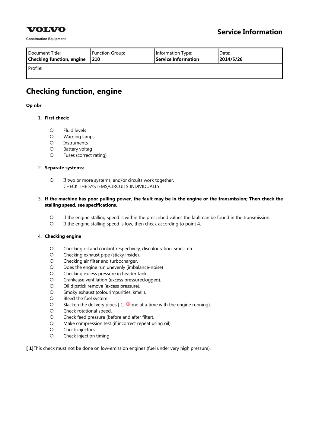
Service Information Document Title: Checking function, engine Function Group: 210 Information Type: Service Information Date: 2014/5/26 Profile: Checking function, engine Op nbr 1. First check: Fluid levels Warning lamps Instruments Battery voltag Fuses (correct rating) 2. Separate systems: If two or more systems, and/or circuits work together. CHECK THE SYSTEMS/CIRCUITS INDIVIDUALLY. 3. If the machine has poor pulling power, the fault may be in the engine or the transmission; Then check the stalling speed, see specifications. If the engine stalling speed is within the prescribed values the fault can be found in the transmission. If the engine stalling speed is low, then check according to point 4. 4. Checking engine Checking oil and coolant respectively, discolouration, smell, etc. Checking exhaust pipe (sticky inside). Checking air filter and turbocharger. Does the engine run unevenly (imbalance-noise) Checking excess pressure in header tank. Crankcase ventilation (excess pressureclogged). Oil dipstick remove (excess pressure). Smoky exhaust (colourimpurities, smell). Bleed the fuel system. Slacken the delivery pipes [ 1] Check rotational speed. Check feed pressure (before and after filter). Make compression test (if incorrect repeat using oil). Check injectors. Check injection timing. one at a time with the engine running). [ 1]This check must not be done on low-emission engines (fuel under very high pressure).
Service Information Document Title: Engine, fitting Function Group: 210 Information Type: Service Information Date: 2014/5/26 Profile: Engine, fitting Op nbr 21072 Lifting sling, 3m Shackle 3/8 Ratchet block, 750 kg (1654 lb) 1. Connect lifting device to the engine according to Fig. 2. Figure 1 Connecting lifting device 1. 2. 3. Lifting sling, 3m Shackle 3/8 Ratchet block, 750 kg (1654 lb) 3. Lifting in the engine in the machine NOTE! Make sure that the hoses for the air conditioning (if fitted) are not damaged!
4. Align the engine with the transmission and fit the bolts. Remove any supports under the transmission. 5. Fit the bolts between engine mountings and rubber cushions. 6. Bolt on the transmission oil cooler in the bracket on the engine. 7. Fit fan belt pulley, hub, bracket and tensioning pulley, see Fig. 8. Figure 2 Fan belt pulley complete with hub, bracket and tensioning pulley 9. Fit belt pulleys on the crankshaft. 10. Bolt on the compressor (if fitted) for the air conditioning and fit its drive belt and the fan belts. 11. Fit the stays between the engine and the air guide ring. 12. Fit the fan 13. Fit the coolant pipe between the coolant pump and the transmission oil cooler, using a new O-ring. Connect the hoses for the header tank, the coolant filter (if fitted) and the cab heater to the pipe. 14. Bolt on the fuel system water trap in the bracket on the frame. Connect the fuel lines to the feed pump and the injection pump. 15. Connect the cable harness to B+ on the alternator, connector BB to the stop solenoid and SE1 to the temperature sensor. Clamp the cable harness using the screw clamps. 16. Connect the governor control rod to the injection pump. 17. Bolt on the preheating coil relay bracket and the bracket for the air conditioning drier filter (if fitted) to the bracket on the engine induction manifold. Connect the lead to preheating coil. 18. Connect the earth lead to the starter motor (black terminal). Connect the red lead of the cable harnesses to the starter motor (red terminal). 19. Connect leads to oil pressure sensor and to dust indicator, clamp using the screw clamps.
https://www.ebooklibonline.com Hello dear friend! Thank you very much for reading. Enter the link into your browser. The full manual is available for immediate download. https://www.ebooklibonline.com
20. Fit the upper radiator hose. 21. Fit the breather filter and bolt on the pump (if fitted) for the secondary steering. 22. Lift the hood unit into position, see Fig. 23. Figure 3 Fitting hood unit 24. Connect as follows: The exhaust pipe to the silencer. The hoses to the header tank, 3 pcs. The hose to the hydraulic tank breather filter. The induction hose to the turbocharger. The hose to the dust indicator. 25. Fit the hood plates on both sides of the hydraulic tank and the cover door at the top. 26. Fill with coolant and engine oil. 27. Remove the steering joint lock, start the engine and check that there are no leaks.
Service Information Document Title: Engine, removing Function Group: 210 Information Type: Service Information Date: 2014/5/26 Profile: Engine, removing Op nbr 21070 Lifting sling, 3m Shackle 3/8 Ratchet block, 750 kg (1654 lb) 1. Secure the steering frame joint with the steering frame joint lock. 2. Turn off the current with the battery disconnect switch. 3. Open the cover to the header tank and drain the coolant. Drain the engine oil. WARNING There is a danger of scalding, when removing the header tank cap (radiator cap), as the cooling system is pressurised when hot. 4. Remove the cover door above and the hood plates on both sides of the hydraulic tank. 5. Disconnect as follows: The exhaust pipe from the silencer. Hoses from header tank, 3 pcs. Hose from hydraulic tank breather filter. Induction hose from the turbocharger. Hose from the dust indicator. 6. Lift away the hood plate above the engine and the side covers as one unit together with silencer, air cleaner and header tank see Fig. 7. Figure 1 Removing hood plate 8. Open the side covers on both sides of the hydraulic tank and remove the lower cover plates. 9. Disconnect the governor control rod from the injection pump.
10. Disconnect necessary leads and remove clamps from: starter motor preheating coil alternator temperature sensor oil pressure sensor and stop solenoid 11. Remove the preheating relay bracket and the bracket for air conditioning drier filter (if fitted) from the bracket by the engine induction manifold. Place the drier filter on the frame without disconnecting the hoses. WARNING Do not disconnect hoses for the air conditioning (AC) (if fitted), otherwise the refrigerant will escape from the system. 12. Loosen the bracket for the engine oil and the coolant draining hoses. Disconnect fuel lines from injection pump and feed pump. Loosen the water trap and put it on the frame 13. Swing out the radiator and condenser (if fitted), remove the fan and the fan hub. Remove the attaching stays, 3 pcs, for the air guide ring. Remove the fan belts and the belt pulley. Also remove the belt pulley for the air conditioning compressor (if fitted) 14. Remove fan belt pulley complete with hub, bracket and tensioning pulley, see Fig. 15. Figure 2 Fan belt pulley complete with hub, bracket and tensioning pulley 16. Remove the breather filter and loosen the secondary steering pump, (if fitted) 17. Free the electrical lead for the air filter dust indicator from the tank 18. Connect a lifting device to the engine, see Fig. Remove the bolts between engine mounting and rubber cushion. Remove the bolts between the engine and the transmission.
19. Figure 3 Connecting lifting device 1. 2. 3. Lifting sling, 3m Shackle 3/8 Ratchet block, 750 kg (1654 lb) 20. Support the transmission against the front rear axle bracket, see Fig. 21. Figure 4 Supporting transmission 1. Wooden blocks 22. Lift away the engine, see Fig. Weight: approx. 750 kg (1654 lb)
23. Figure 5 Lifting out engine
Service Information Document Title: Specifications, L90B Function Group: 210 Information Type: Service Information Date: 2014/5/26 Profile: Specifications, L90B Where tolerance limits have been given and unless otherwise stated, these apply to new parts and are not wear tolerances Weights (approx.) kg lb Engine, standard 660 1455 Capacities litres US gal Engine incl. filter Engine, when changing oil incl. filter 17 16 4.5 4.2 Unless otherwise stated the data are the same for all three versions of the engine, i.e. basic version, low emission version and high-altitude version. General Designation, basic version Designation, low emission version Flywheel output at 36.7 r/s (2200 rpm) Basic version and high-altitude version Flywheel output at 36.7 r/s (2200 rpm) Low emission version Output, gross at 36.7 r/s (2200 rpm) Basic version and high-altitude version Output, gross at 36.7 r/s (2200 rpm) Low emission version Torque at 23.3 r/s (1400 rpm) Basic version and high-altitude version Torque at 26.7 r/s (1600 rpm) Low emission version Number of cylinders Cylinder bore Stroke Cylinder capacity, total Compression ratio Compression pressure at starter motor revolutions, 3.3 r/s (200 rpm) Order of injection Idling speed, low Idling speed, high Stalling speed, torque converter TD61G, engine no. 497993 TD61KBE, engine no. 497994 109 kW (148 hp) SAE J 1349 Nett 109 kW (148 hp) DIN 70020 113 kW (154 hp) SAE J 1349 Nett 113 kW (154 hp) DIN 70020 115 kW (156 hp) SAE J 1349 Gross 119 kW (162 hp) SAE J 1349 Gross 630 N m (465 lbf ft) SAE J 1349 Nett 640 N m (472 lbf ft) SAE J 1349 Gross 630 N m (465 lbf ft) DIN 70020 660 N m (487 lbf ft) SAE J 1349 Nett 670 N m (494 lbf ft) SAE J 1349 Gross 660 N m (487 lbf ft) DIN 70020 6 98.43 mm (3.875 in) 120 mm (4.724 in) 5.48 litres 16:1 2.4 MPa (24 bar) (348 psi) 1-5-3-6-2-4 11.2 0.5 r/s ( 670 30 rpm) (435 30 Hz) 39.7 1.0 r/s (2380 60 rpm)(1546 60 Hz) 35 1.25 r/s (2100 75 rpm) (1365 75 Hz)
Stalling speed, torque converter + working hydraulics 26.5 1.7 r/s (1600 100 rpm)(1040 75 Hz)
Service Information Document Title: Specifications Function Group: 214 Information Type: Service Information Date: 2014/5/26 Profile: Specifications Unless otherwise stated the data are the same for all three versions of the engine, i.e. basic version, low emission version and high-altitude version. Valve clearance, cold / warm engine inlet valves exhaust valves 0.40 mm (0.016 in) 0.55 mm (0.022 in)
Service Information Document Title: Specifications Function Group: 218 Information Type: Service Information Date: 2014/5/26 Profile: Specifications Important! Nuts and bolts which are not listed here, see [Invalid linktarget] . Engine See also separate Service Manual for the engine. N m 78 kgf m lbf ft Flywheel housing torque converter housing Cylinder block mounting Mounting tapered rubber damper Rear frame tapered rubber damper 7.8 58 78 190 7.8 19 58 140 45 4.5 33
Service Information Document Title: Specifications, L90B Function Group: 220 Information Type: Service Information Date: 2014/5/26 Profile: Specifications, L90B Unless otherwise stated the data are the same for all three versions of the engine, i.e. basic version, low emission version and high-altitude version. General Oil pressure Oil pressure, low idling, minimum Relief valve[ 1] Piston cooling valve* "red marking", opening pressure 300 - 500 kPa (3 - 5 bar) (44 - 73 psi) 50 kPa (0.5 bar) (7.2 psi) 470 kPa (4.7 bar) (68 psi) 370 kPa (3.7 bar) (54 psi) "blue marking", opening pressure [ 1]The valves are made in one piece and cannot be dismantled. The valve marked "blue" is fitted nearest the cylinder block.
Service Information Document Title: Checking rotational speed with frequency meter Function Group: 230 Information Type: Service Information Date: 2014/5/26 Profile: Checking rotational speed with frequency meter Op nbr Frequency meter If the machine is not provided with a display unit and there is no service display unit available, the rotational speed can be checked with a frequency meter. The signal, which is checked, is the signal which the control unit (ECU) obtains from the speed sensor. The following applies when checking: L90B: Low idling speed: High idling speed: L120B: Low idling speed: High idling speed: 435 20 Hz 1546 40 Hz 435 20 Hz 1580 40 Hz Temperature: Units using a lot of electricity and any AC-unit should be turned off. Normal working temperature Conversion factor, frequency to engine speed: r/s rpm = obtained frequency x 0.0256 = obtained frequency x 1.54 1. 2. Remove the wall lining by the electrical distribution box. 3. Disconnect the connector OA from the circuit board. 4. The frequency (rotational speed) is checked in connector OA at pin 1 (signal) and at pin 2 (chassis connection), see Fig. 5. Figure 1 Checking rotational speed with frequency meter 1. Connector OA
2. 3. Signal (+) Chassis connection (-) NOTE! The machine travelling speed can be checked in the same connector (OA) at pin 4 (signal) and at pin 2 (chassis connection). Conversion factor, frequency to speed (km/h): L90B L120B = Obtained frequency x 0.0249 = Obtained frequency x 0.0212 When checking idling speed, also see "IDLING SPEED, CHECKING AND ADJUSTING" points 2 and 3. [Invalid linktarget]
Service Information Document Title: Fuel system, bleeding Function Group: 230 Information Type: Service Information Date: 2014/5/26 Profile: Fuel system, bleeding Op nbr 23301 E 1351 Spanner 1. Slacken the bleeder screw on the filter head. Pump with the hand pump until fuel free from air bubbles flows out. Tighten the bleeder screw. 2. Slacken the pressure equaliser slightly using E 1351 at the back of the injection pump and repeat the pumping with the hand pump as described above. 3. Slacken the delivery pipes at the injectors and crank the engine with the starter motor until fuel free of air bubbles squirts out. Tighten the delivery pipe unions. 4. Start the engine and check that there are no leaks. 5. Fuel system, bleeding, L90B Figure 1 Fuel system, bleeding, L90B A. B. C. D. Bleeder screw, filter head Hand pump, feed pump Pressure equaliser Delivery pipe 6. Fuel system, bleeding, L120B
Figure 2 Fuel system, bleeding, L120B A. B. C. D. Bleeder screw, filter head Hand pump, feed pump Pressure equaliser Delivery pipe
Suggest: If the above button click is invalid. Please download this document first, and then click the above link to download the complete manual. Thank you so much for reading
Service Information Document Title: Idling speed, checking and adjusting Function Group: 230 Information Type: Service Information Date: 2014/5/26 Profile: Idling speed, checking and adjusting Op nbr 23601 9993721 Service display unit* *Is used when the machine is not provided with display unit [ 1] The following applies when checking: L90B: Low idling speed: High idling speed: L120B: Low idling speed: High idling speed: 670 30 rpm 2380 60 rpm 670 30 rpm 2430 60 rpm Temperature: Units using a lot of electricity and any AC-unit should be turned off. Normal working temperature 1. 2. Display the information about the engine and engine speed on the display unit, see Fig. 3. Figure 1 Measuring engine speed 1. 2. Display unit [ 2] Point of connection for service display unit, 3721 (under the instrument panel) 4. Check that the governor control arm fits up against the adjusting screw 1, see Fig. Start the engine and read off the low idling speed on display unit. Any adjustments are carried out with adjusting screw 1, see Fig. Lock the adjusting screw with a nut and check the engine speed.
https://www.ebooklibonline.com Hello dear friend! Thank you very much for reading. Enter the link into your browser. The full manual is available for immediate download. https://www.ebooklibonline.com