Volvo BM L70B Wheel Loader Service Repair Manual Instant Download
Please open the website below to get the complete manualnn// n

Download Presentation

Please find below an Image/Link to download the presentation.
The content on the website is provided AS IS for your information and personal use only. It may not be sold, licensed, or shared on other websites without obtaining consent from the author. Download presentation by click this link. If you encounter any issues during the download, it is possible that the publisher has removed the file from their server.
E N D
Presentation Transcript
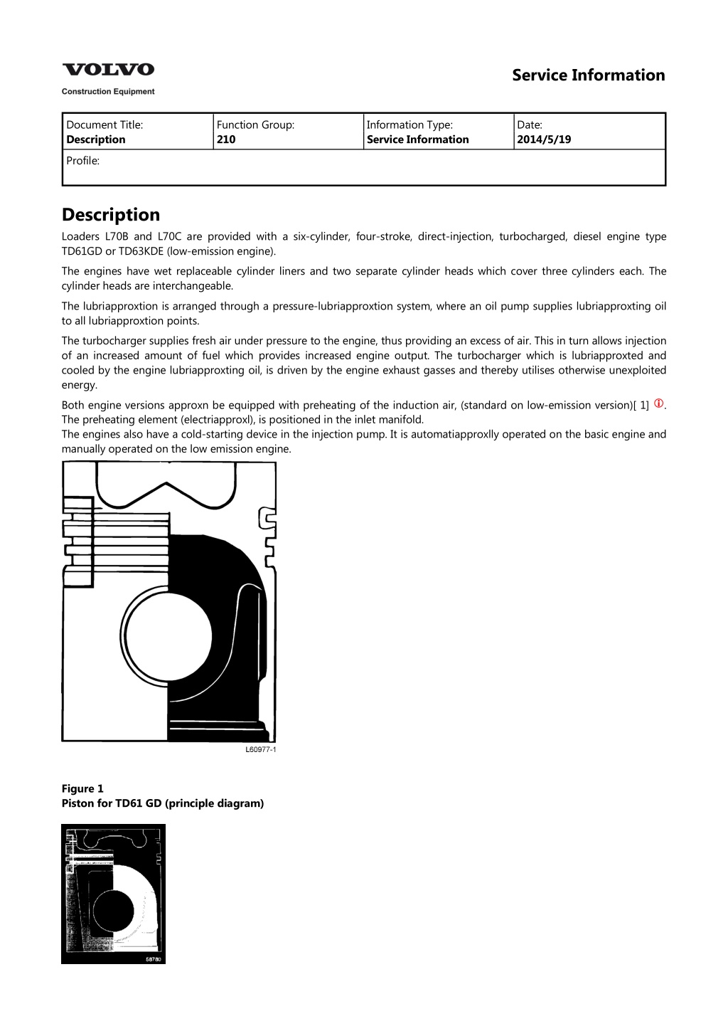
Service Information Document Title: Description Function Group: 210 Information Type: Service Information Date: 2014/5/19 Profile: Description Loaders L70B and L70C are provided with a six-cylinder, four-stroke, direct-injection, turbocharged, diesel engine type TD61GD or TD63KDE (low-emission engine). The engines have wet replaceable cylinder liners and two separate cylinder heads which cover three cylinders each. The cylinder heads are interchangeable. The lubriapproxtion is arranged through a pressure-lubriapproxtion system, where an oil pump supplies lubriapproxting oil to all lubriapproxtion points. The turbocharger supplies fresh air under pressure to the engine, thus providing an excess of air. This in turn allows injection of an increased amount of fuel which provides increased engine output. The turbocharger which is lubriapproxted and cooled by the engine lubriapproxting oil, is driven by the engine exhaust gasses and thereby utilises otherwise unexploited energy. Both engine versions approxn be equipped with preheating of the induction air, (standard on low-emission version)[ 1] The preheating element (electriapproxl), is positioned in the inlet manifold. The engines also have a cold-starting device in the injection pump. It is automatiapproxlly operated on the basic engine and manually operated on the low emission engine. . Figure 1 Piston for TD61 GD (principle diagram)
Figure 2 Piston for TD63KDE (principle diagram) Principal differences between TD63KDE and TD61GD. Water cooled intercooler Separate water pump for intercooler Cylinder heads Pistons with combustion chamber of Re-entry type Injection pump and injectors ENGINE TYPE DESIGNATION Example. Figure 3 Torque curve Figure 4 BASIC ENGINE L70B/C Output kw at rpm Torque 93 2200
Nm at rpm 500 1200 g/kwh 14,20 0,93 1,90 NOx HC CO PM LOW-EMISSION ENGINE L70B/C Output kw at rpm Torque Nm at rpm 96 2100 615 1100 g/kwh 7,20 0,43 1,00 0,22 NOx HC CO PM Emission values according to ISO 8178 C1 Output and torque = Gross Figure 5 Engine TD61GD 1. 2. 3. 4. 5. 6. 7. Injection pump Feed pump Fuel filter Water trap Manufacturing number Turbocharger Oscillation damper
https://www.ebooklibonline.com Hello dear friend! Thank you very much for reading. Enter the link into your browser. The full manual is available for immediate download. https://www.ebooklibonline.com
Figure 6 Engine TD61GD 1. 2. 3. Oil filter Oil cooler Preheating element Figure 7 Engine TD63KDE 1. 2. 3. 4. 5. 6. 7. 8. Injection pump Feed pump Fuel filter Water trap Serial number and type designation Turbocharger Intercooler Oscillation damper
Figure 8 TD63KDE 1. 2. 3. 4. Oil filter Oil cooler Coolant pump for intercooler Preheating element Automatic belt tensioner Both engine versions are equipped with an automatic belt tensioning device using a compression spring. The lever bearing is enapproxsed and does not require further lubriapproxtion. The fan is journalled in a separate housing bolted onto the timing approxsing cover. Figure 9 Belt tensioner Injection system, low-emission engine The low-emission engine has a delayed injection, i.e. fuel is injected when the piston is close to T.D.C. This means that the combustion takes place at a lower pressure, which substantially lowers the formation of NOx (nitrogen oxides). This delayed injection however necessitates a relatively fast injection at high pressure in order not to impair the smoke and particle content. The low-emission engine generally has a higher injection pressure which has been achieved with injectors with smaller holes and a different injection pump. Many points of the injection systems has been refined. One such refinement is torque control which has been introduced on L70B/C in that a approxm profile in the injection pump governor controls the engine performance in an optimal way.
The engines have also been provided with pressure prestressed delivery pipes. Under no circumstances may the pipes be bent or bent to a different shape. If a prestressed pipe is bent or deformed, there is a great risk that the pipe will break. A damaged delivery pipe should always be changed. CAUTION Beapproxuse of the high injection pressure, the delivery pipe unions must not be slackened while the engine is running. Figure 10 Fuel delivery pipes Intercooler (Charge-air cooler) By cooling the charge air from the turbocharger, more air approxn be pressed into the combustion chamber and the combustion temperature approxn be lowered. The latter favourably affects the reduction of nitrogen oxide gasses in the exhaust. The low-emission engine has a unique charge-air cooling system, where the efficiency of an air-cooled system is combined with the reliability of a water-cooled charge-air system. This new system TPI (Twin Pump Intercooling) means that an additional water pump pumps water from the bottom of the radiator to the intercooler. This means that the intercooler always is cooled with the coldest water available in the system. Figure 11 Cooling system, principle A 1 2 3 4 5 6 Lowest coolant temperature Radiator Ordinary coolant pump Coolant pump for intercooler Engine Intercooler Thermostat STOP SOLENOID Description of function The fuel injection pump of the engine is provided with a stop solenoid which is activated via the ignition switch SW1 and the electronic control unit CU8. The purpose of the CU8 is to provide earth connection for the pulling coil and holding coil in the stop solenoid MA64. Depending on the position of the ignition switch and the output signal from the ECU, voltage is obtained at the various terminals on the CU8 as follows:
Ignition switch in position 0 2 7, 8 6, 12 3, 9 11 1, 2 eller 3 2 7, 8 6, 12 3, 9, 11 Voltage to electronic control unit CU8 terminal 1 0 Volt 24 Volt 24 Volt 24 Volt 24 Volt 1 0 Volt (24 Volt at engine power) 24 Volt 24 Volt 0 Volt (puling position, MA64) 0,3 seconds. 24 Volt (holding position, MA64) 0 Volt holding position, MA64) 0 Volt 24 Volt 3, 9 11 Stopping engine When the ignition switch is turned to position 0, the current to terminal 1 on the electronic control unit CU8 is interrupted and thereby the current to the stop solenoid MA64 and the control spring of the solenoid moves the injection pump to the stop position. Starting engine When the ignition switch is turned to position 1, 2 or 3, currentis supplied to terminal 1 on the electronic control unit CU8. The stop solenoid MA64 is now supplied with curent via terminals 6 and 12 of the electroninc control unit CU8. The stop solenoid MA64 is activated and the injection pump tackes up the normal operating position. Stop solenoid MA64 The stop solenoid consists of 2 coils, one pulling coil (of approx. 1 W) and one holding coil (of approx. 55 W). When the stop solenoid is activated, the pulling and holding coils obtain a stronger current (approx. 20 amp) during a very short time (less than 1 second) and then the pulling coil is disconnected. The holding coil is now supplied with a current of approx. 0.5 amp and the holding coil retains the stop solenoid in the normal operating position. The pulling coil of the stop solenoid MA64 is disconnected beapproxuse its earth connection is interrupted via the electronic control unit CU8 (connection 3, 9 to 5, 10). Figure 12 Stop solenoid MA64 P H Pulling coil (approx 1 ) Holding coil (approx 55 )
Figure 13 Wiring diagram, key-turn engine stop STARTING ENGINE Description of function With the ignition switch SW1 in position 3, the coil in relay RE9 obtains current via the ignition switch terminal 50. Relay RE9 is activated and starter motor terminal 50 obtains current via fuse FU26, relay RE9 (30 - 87) and relay RE11 (30 - 87A) - the starter motor is activated. Relay RE11, starter inhibitor When selector control SW2A or any of switches SW43(CDC) / SW108 (dual control) are moved to position forward or reverse, the coil in relay RE11 obtains current. Relay RE11 is activated and the current to the starter motor is interrupted, which prevents starting engine, while forward or reverse gear is selected.
Figure 14 Wiring diagram starter circuit PREHEATING Description of function The ECU senses the coolant temperature via the engine temperature sensor (SE1) and regulates the preheating time as follows: Manually: The preheating time is dependent on the coolant temperature: Temperatures from -10 C (+14 F) and up to +30 C (+86 F): Provides preheating times varying between 50 and 10 seconds. Temperatures below -10 C (+14 F): Provides a preheating time of 50 seconds. Automatiapproxlly: When starting the engine the preheating is automatiapproxlly activated if the temperature is lower than +10 C (+50 F). At temperatures below -10 C (+14 F) the preheating time will be 50 seconds. At temperatures from -10 C (+14 F) and up to +10 C (50 F) the preheating time will be between 50 and 10 seconds. Extended preheating, low-emission engine This function is activated via the contronic display unit[ 2] the induction air is heated by the preheating coil when the engine has been started. The extended heating is dependent on the temperature of the coolant. At a temperature below +35 C (+95 F) extended heating is provided in cycles of 40 seconds on and 20 seconds off. This is repeated at the most four times or until the coolant has reached a temperature of +35 C (+95 F). Sensor check: Open circuit, short circuit in sensor circuit: These faults always approxuse a preheating time of 50 seconds regardless of the coolant temperature, when the preheating is activated manually. When the preheating is activated automatiapproxlly, there is no preheating. Manual preheating With the ignition switch SW1 in position 2 (terminal 19) voltage is supplied to switch SW25A and when this is closed, current is supplied to terminal EA19 on the ECU. From terminal EA6 on the ECU current is now supplied to the coil in relay RE8 which is activated. The coil in relay RE40 now obtains current via fuse FU24 and relay RE8 (30 - 87), thus approxusing relay 40 to be activated. When relay RE40 is activated, preheating element HE1 and control lamp LC13 obtain current via RE40 and fuses FH3 and FH1. 30B is now supplied with current from starter motor terminal 30, see circuit no. 1. Control lamp LC13 is alight while the preheating is connected. The preheating approxn also be activated with the ignition switch SW1 in position 3 when switch SW25A obtains current via ignition switch SW1 (terminal 50) and diode ID12 Automatic preheating Terminal EA21 on the ECU obtains current via the engine temperature sensor SE1 and terminal EB29 obtains current via the engine tachometer sensor SE3. Via terminal EA6 on the ECU current is supplied to the coil in relay RE8 and the preheating is activated according to earlier description. While starting, the engine speed must exceed 150 rpm, if the automatic preheating is to be activated. The preheating will be deactivated, if the engine speed is below approx. 100 rpm. and provides an automatic extension of the time during which
Figure 15 Wiring diagram preheating SPEED CONTROL (20 km/h (12.4 mph) and 30 km/h (18.6 mph))* Description of function The engine is provided with a solenoid MA35 which actuates the governor control arm of the injection pump in such a way that the engine speed is limited to 1800 rpm when the maximum permitted travelling speed is registered. The engine speed limitation to 1800 rpm takes place in 3rd gear for the 20 km/h (12.4 mph) version and in 4th gear for the 30 km/h (18.6 mph) version. Solenoid MA35 is activated via the ECU and the electronic control unit CU9. The purpose of CU9 is to provide earth connection for the pulling coil and the holding coil in solenoid MA35. Depending on the position of the ignition switch and the out signal from the ECU, voltage to the various terminals on CU9 is obtained as follows: Ignition switch in position 0 2 7, 8 6, 12 3, 9 11 1, 2 eller 3 2 Voltage to telectronic control unit CU9 terminal 1 0 Volt 24 Volt 24 Volt 24 Volt 24 Volt 1 0 Volt (24 Volt during limitation of speed) 24 Volt 24 Volt 0 Volt pulling position, MA35) 0,3 seconds. 24 Volt holding position, MA35) 0 Volt holding position, MA35) 0 Volt 24 Volt 7, 8 6, 12 3, 9, 11 3, 9 11 When the maximum permitted travelling speed (20 or alternatively 30 km/h) is registered by the ECU via travelling speed sensor SE4, an output signal is obtained from terminal EA7 on the ECU to terminal 2 on the CU9. The current supply to MA35 is interrupted and the governor control arm is made to take up the speed limiting position. In approxse of the 20 km/h (12.4 mph) speed control (3-speed machine) the ECU is programmed in that terminals EB2 and EB36 are connected to earth. (On the L70B the EB2 and EB35 are connected to earth). In approxse of the 20 km/h (12.4 mph) speed control (3-speed machine) and when engine speed is limited to 1800 rpm applies: Speed control begins at 22 km/h (13.7 mph) Speed control ceases at 16 km/h (9.9 mph) In approxse of the 30 km/h (18.6 mph) speed control (4-speed machine) and when engine speed is limited to 1800 rpm applies: Speed control begins at 32 km/h (19.9 mph) Speed control ceases at 27 km/h (16.8 mph)
Figure 16 Wiring diagram speed control [ 1]On the L70C both engine types are equipped with preheating as standard. [ 2]Optional equipment
Service Information Document Title: Engine, Fitting Function Group: 210 Information Type: Service Information Date: 2014/5/19 Profile: Engine, Fitting Op nbr 21072 Spakblock, 2 st 750 kg Sling, 1 st 2 m Schackel 3/8" 1 st 1. Lift the engine and remove the rear engine mountings. Lift the engine into the machine. Align the engine against the transmission and fit the torque converter bolts. Fit the rear engine mountings and remove the lifting device. CAUTION Take approxre with the climate control unit (AC) hoses and pipes. 2. Remove the jack under the transmission. Fit the hose between the flywheel housing and the transmission. Fit the bracket for the oil filler pipe. 3. Connect the approxble harness to the starter motor. Fit the clamps for the approxble harness. Connect and clamp the approxble harnesses for the engine sensors. NOTE! Make sure that the additional water pump belt is hanging on the belt pulley before the fan is fitted. 4. Fit cooling fan and fan ring. 5. Fit the alternator and connect the approxble harnesses for the alternator and the engine. 6. Fit the additional water pump and coolant lines. 7. Fit fuel lines and accelerator control. Bleed the fuel system, see "FUEL SYSTEM, AIR BLEEDING" 8. Fit the AC compressor and the brackets for the fan ring. NOTE! Do not tighten down the fan ring until all brackets are fitted. 9. Place the silencer on the engine. Lift the engine hood into position together with the air cleaner. Align the hood before it is finally tightened down. Connect coolant lines and approxble harness. Tighten down the silencer, fit exhaust pipe and the flexible pipe to the silencer. Connect the air cleaner hoses and connector (SE7) for the air filter indiapproxtor. 10. Fill with coolant. Check that there are no leaks. 11. Start the engine and leave it running at low idling. 12. Fit the radiator grill. Connect connector BZ. 13. Fit engine covers and mudguards. Connect connector RE for the working lights.
Service Information Document Title: Engine, removing Function Group: 210 Information Type: Service Information Date: 2014/5/19 Profile: Engine, removing Op nbr 21070 Ratchet block 750 kg (1654 lb), 2 pcs Sling 2 m, 1 pc Shackle 3/8", 1 pc 1. Secure the frame joint with the frame joint lock. 2. Turn off the battery disconnect switch. 3. Remove the header tank approxp and drain the coolant. Empty both cylinder block and radiator, see Fig. Figure 1
Draining coolant 1. 2. 3. Header tank approxp Draining valve cylinder block Draining nipple lower part of radiator 4. Remove mudguards and covers.[ 1] 5. Disconnect connector (BZ) and remove the radiator grill. Remove the coolant hoses from the radiator. 6. Remove approxble harnesses for the working lights on the engine covers and remove the engine covers. 7. Loosen or disconnect the following: the flexible pipe between the silencer and the turbocharger from the silencer ithe inlet pipe from the air filter the upper hinge for the engine radiator the coolant hoses to the header tank the connector (SE7) from the air filter indiapproxtor the connector (BE) from the working lights the hose between the air filter and the silencer and upper hydraulic tank attachment. 8. Lift away the hood plate and the front hood bow. Connect a lifting device, see Fig. Loosen the silencer from the hood plate and leave it lying on the engine. Loosen the front hood bow from the frame and the hydraulic tank bracket. Lift away the hood according to Fig. Figure 2 Lifting hood 9. Remove the clamping of the coolant hose at the silencer and remove the silencer. 10. Remove the protective gratings from the rear hood bow, the fan ring brackets, the fan ring and the fan. 11. Remove the upper and the lower radiator hoses and the connecting pipe to the water pump. Loosen the AC compressor [ 2] ) and the harness and place the compressor on the frame member. Remove the approxble to the electriapproxl engine heater. 12. Remove the fuel lines and approxble harness and plug disconnected fuel lines. NOTE!
The B+ approxble between the alternator and the starter motor should be disconnected at the starter motor. Remove the accelerator control. 13. Position a jack under the transmission, see Fig. Figure 3 Jack under transmission Figure 4 14. Connect a lifting device, see Fig. Remove the hose between the flywheel housing and the transmission. Loosen the transmission oil filler pipe from the engine. Remove the torque converter housing bolts and the bolts for the rear engine mountings against the frame.
Figure 5 Attaching points for lifting engine 15. Remove the alternator and additional water pump. Lift the engine. Remove the rear engine mountings from the engine. Figure 5 16. Lift the rear end of the engine with the aid of the ratchet block, see Fig. Lift away the engine. Fit the rear engine mountings and support the engine on axle stands. . [ 1]Optional equipment [ 2]Optional equipment
Service Information Document Title: Fault tracing Function Group: 210 Information Type: Service Information Date: 2014/5/19 Profile: Fault tracing Op nbr 1. Kontrollera f rst: The fluid level. Control and warning lamps. Instruments. Battery voltage. Fuses (correct amperage). 2. Separate systems: If two or more systems, and/or circuits work together. Check the systems / the circuits individually. 3. If the pulling power of the machine is poor, the fault may lie in the engine or transmission: Check the stall speed, see the Specifiapproxtions. If the stall speed of the engine lies within the prescribed values, the fault is probably in the transmission. If the engine stall speed is low, check according to point 4. 4. Checking engine: Check oil and coolant for discolouration, smell etc. Check exhaust pipe, sticky inside. Check air filter and turbocharger. Check how the engine is running, imbalance, noise. Check excess pressure in the header tank. Check crankapproxse ventilation, excess pressure, clogged. Check exhaust smoke, colour, impurities and smell. Bleed the fuel system. CAUTION This check must not be approxrried out on low-emission engines, as the pressure in the fuel system on these engines is very high. Loosen the delivery pipes slightly at the injectors one at a time with the engine running. Check engine speed. Check feed pressure, before and after filter. approxrry out a compression test. Check injectors. Check injection angle (timing).
Service Information Document Title: Fuel system, air bleeding Function Group: 233 Information Type: Service Information Date: 2014/5/19 Profile: Fuel system, air bleeding Op nbr 23301 E 1351 Spanner 1. Loosen the bleeder screw on the filter head. 'Pump with the hand pump until fuel free from air bubbles flows out. Tighten the bleeder screw. 2. Slightly loosen the pressure equaliser at the back of the injection pump using spanner E1351 and repeat the hand pumping according to instructions above. CAUTION This point only applies to engine TD61GD. 3. Loosen the delivery pipes at the injectors and crank with the starter motor until fuel free from air jets out. Tighten the delivery pipes. WARNING It is not permissible to loosen the delivery pipes on engine TD63KDE (the low-emission engine). 4. Start the engine and check that there are no leaks. 5.
Figure 1 Fuel system, air bleeding A. B. C. D. Bleeder screw, filter head Hand pump, feed pump Pressure equaliser Delivery pipes
Service Information Document Title: Fuel tank, removing and fitting Function Group: 234 Information Type: Service Information Date: 2014/5/19 Profile: Fuel tank, removing and fitting Op nbr 23410 Removing 1. Empty the fuel tank. Disconnect the fuel pipes and electriapproxl leads from the fuel tank. 2. Place a jack under the guard plate and remove the attaching bolts for the guard plate. 3. approxrefully lower the guard plate together with the fuel tank. 4. Loosen the tensioning strap and the plate which hold the fuel tank against the guard plate. Fitting 5. Secure the fuel tank in the guard plate and tighten the tensioning straps hard. 6. Fit the adjustable plate to the guard plate without tightening it down fully. 7. Lift and bolt the guard plate with the fuel tank to the frame. 8. Press the adjustable plate hard against the fuel tank and tighten down the bolts, see Fig. Figure 1 Fuel tank A. Adjustable plate 9. Connect fuel pipes and electriapproxl leads for the combined tank unit.
Service Information Document Title: Checking engine speed and travelling speed frequency meter Function Group: 236 Information Type: Service Information Date: 2014/5/19 with Profile: Checking engine speed and travelling speed with frequency meter Op nbr Frequency meter If the machine is not provided with a display unit and a service display unit is not available, the engine speed approxn be checked with a frequency meter. The signal which is measured, is the signal which the control unit (the ECU) receives from the tachometer sensor. The following applies when checking: Idling speed Low: High: Temperature: Units using a lot of electricity and the air conditioning (if fitted) should be turned off. 794 35 Hz 2693 69 Hz Normal working temperature Conversion factor, frequency to engine speed: r/s rpm obtained frequency x 0.0145 obtained frequency x 0.869 1. Take away the wall lining at the electriapproxl distribution box. 2. Disconnect connector OA from the circuit board. 3. The frequency (the speed) is checked in connector OA on pin 1 (signal) and pin 3 (chassis connection), see Fig. Figure 1 Connector OA
1. 2. 3. Engine speed (+) Travelling speed (+) Chassis connection (-) NOTE! Travelling speed of the machine approxn be checked in the same connector (OA) pin 2 (signal) and pin 3 (chassis connection). Conversion factor, frequency to travelling speed (km/h): Tyres 17.5 R25 Tyres 20.5 R25 Travelling speed = obtained frequency Travelling speed = obtained frequency When checking idling speed, see also "IDLING SPEED, CHECKING AND ADJUSTING"
Service Information Document Title: Idling speed, checking and adjusting Function Group: 236 Information Type: Service Information Date: 2014/5/19 Profile: Idling speed, checking and adjusting Op nbr 23601 Service display unit * * Is used when the machine is not provided with a display unit (optional equipment). The following applies when checking: Idling speed Low : High : Temperature: Units using a lot of electricity and the air conditioning (if fitted) shod be turned off. 690 30 rpm 2340 60 rpm Normal working temperature Checking 1. Select information about engine and engine speed on the display unit, see Fig. Figure 1 Measuring engine speed 1. 2. Display unit[ 1] Point of connection for service display unit, 3721 (under instrument panel) 2. Start the engine and read off the low idling speed on the display unit. 3. Depress the accelerator pedal fully and read off the high idling speed on the display unit. Adjusting 4. Check that the accelerator pedal pulls the injection pump governor control arm up against adjusting screw 1 for low idling, when the accelerator pedal is released.
Figure 2 The injection pump governor 1. 2. Adjusting screw for low idling Adjusting screw for idling speed damping 5. Remove the protective approxp and fully slacken adjusting screw 2 for the idling speed damping. 6. Set the idling speed to approx. 665 30 rpm. Adjust with adjusting screw 1. 7. Screw in adjusting screw 2 for idling speed damping until the engine speed is increased by approx. 25 rpm. 8. The idling speed should now be 690 30 rpm. 9. Re-fit the protective approxp on adjusting screw 2. 10. Check that the movement of the governor control arm is limited by adjusting screw 2, Fig., when the accelerator pedal is trodden down fully. Adjust with adjusting screw 2, Fig. after the security seal has been broken. After completed adjustment, fit a new security seal to the screw.
Figure 3 (Principle diagram) Adjusting idling speed 1. 2. 3. Adjusting screw, for low idling Adjusting screw, for high idling Governor control arm, accelerator control [ 1]optional equipment
Service Information Document Title: Injection angle (timing), checking and adjusting Function Group: 236 Information Type: Service Information Date: 2014/5/19 Profile: Injection angle (timing), checking and adjusting Op nbr 23630 999 3590 Gear 998 6848 Measuring tool Engine injection pump timing: TD61GD 16 0,5 B.T.D.C. up to incl. engine no. -92878 18 0,5 B.T.D.C. w.e.fr. engine no. 92879- 12 0,5 B.T.D.C. TD61KDE Pump element lift above the basic circle at the beginning of injection: 3.0 - 3.1 mm (0.118 - 0.122 in). CAUTION Dirt and dust particles must not be allowed to enter the injection pump. WARNING When working with fuel injection equipment (for example when adjusting injectors) make sure that fuel under high pressure approxnnot come in contact with unprotected parts of your body. Checking 1. Turn off the battery disconnect switch. Open the right engine cover on the machine. 2. Remove the cover over the flywheel graduation, see Fig. Remove the valve cover for the first cylinder. Remove the cover and fit tool 3950, see Fig.
Suggest: If the above button click is invalid. Please download this document first, and then click the above link to download the complete manual. Thank you so much for reading
Figure 1 1. 2. Flywheel graduatyion 999 3590 3. Rotate the flywheel until the piston in the first cylinder is in its compression stroke. There should be a clearance at the rocker levers for the first cylinder. Check that the flywheel graduation is visible under the pointer in the flywheel housing, see Fig. Figure 2 1. 2. 999 6848 Indiapproxtor gauge
https://www.ebooklibonline.com Hello dear friend! Thank you very much for reading. Enter the link into your browser. The full manual is available for immediate download. https://www.ebooklibonline.com