Volvo BM L50B Wheel Loader Service Repair Manual Instant Download
Please open the website below to get the complete manualnn// n

Download Presentation

Please find below an Image/Link to download the presentation.
The content on the website is provided AS IS for your information and personal use only. It may not be sold, licensed, or shared on other websites without obtaining consent from the author. Download presentation by click this link. If you encounter any issues during the download, it is possible that the publisher has removed the file from their server.
E N D
Presentation Transcript
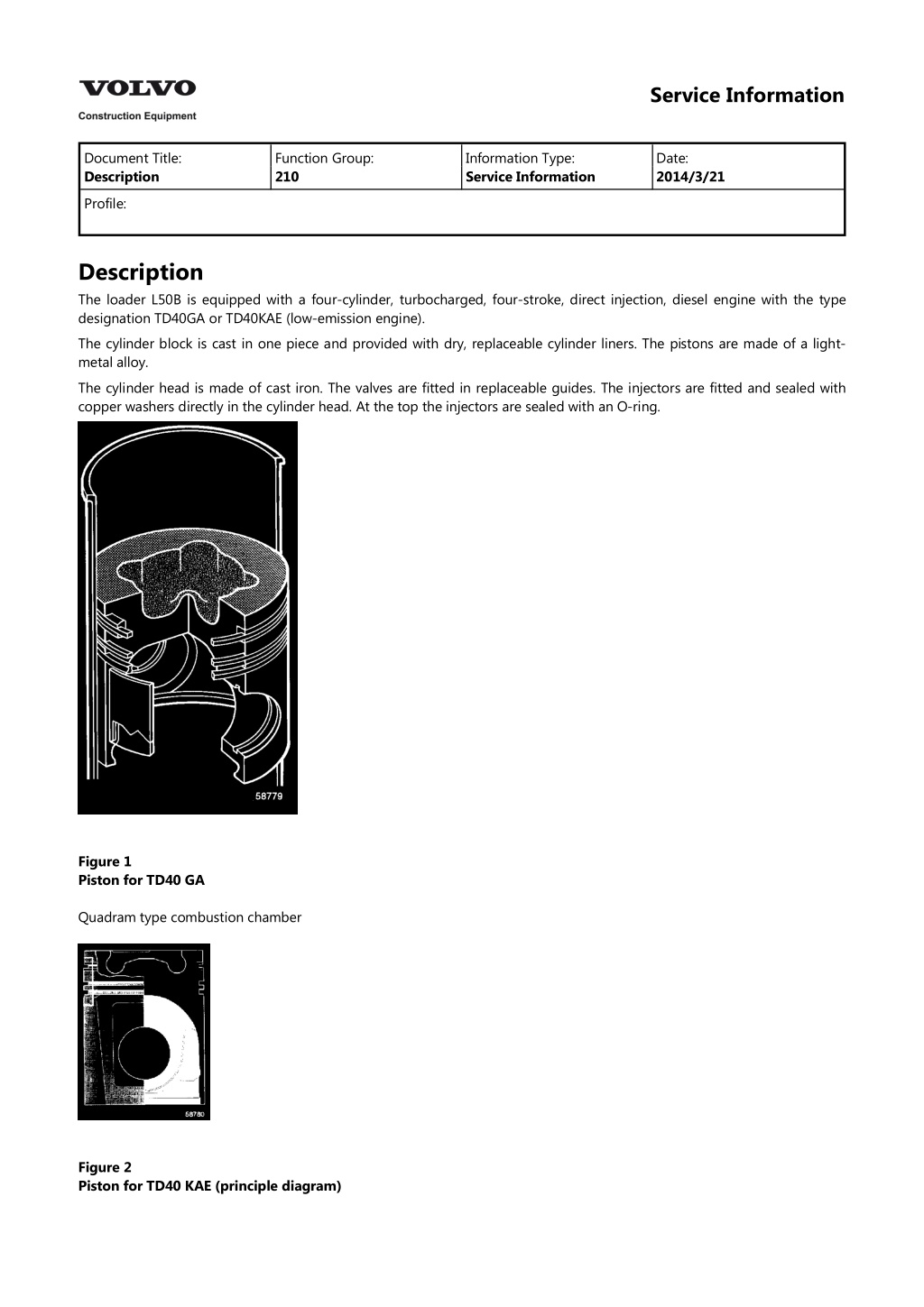
Service Information Document Title: Description Function Group: 210 Information Type: Service Information Date: 2014/3/21 Profile: Description The loader L50B is equipped with a four-cylinder, turbocharged, four-stroke, direct injection, diesel engine with the type designation TD40GA or TD40KAE (low-emission engine). The cylinder block is cast in one piece and provided with dry, replaceable cylinder liners. The pistons are made of a light- metal alloy. The cylinder head is made of cast iron. The valves are fitted in replaceable guides. The injectors are fitted and sealed with copper washers directly in the cylinder head. At the top the injectors are sealed with an O-ring. Figure 1 Piston for TD40 GA Quadram type combustion chamber Figure 2 Piston for TD40 KAE (principle diagram)
Re-entry type combustion chamber The main differences between TD40KAE and TD40GA. Injection pump of the in-line type. Different injectors. Turbocharger with waste-gate valve. Water-cooled intercooler. Separate water pump for the intercooler. Pistons with combustion chamber of the Re-entry type. Double preheating coils. Figure 3 Engine TD40 GA 1. 2. 3. 4. Injection pump, (distribution type pump) Engine number, (behind the injection pump) Fuel filter Oil cooler Figure 4 Engine TD40 GA 1. 2. 3. Fuel feed pump Turbocharger Preheating, (type thermostart)
Figure 5 Engine TD40 KAE 1. 2. 3. 4. 5. Fuel feed pump Injection pump, (in-line pump) Engine number, (behind the injection pump) Fuel filter Oil cooler Figure 6 Engine TD40 KAE 1. 2. 3. 4. Turbocharger with waste-gate valve Preheating coil Intercooler Separate water pump for intercooler
https://www.ebooklibonline.com Hello dear friend! Thank you very much for reading. Enter the link into your browser. The full manual is available for immediate download. https://www.ebooklibonline.com
Service Information Document Title: Fuel system, air bleeding (TD40 GA) Function Group: 233 Information Type: Service Information Date: 2014/3/21 Profile: Fuel system, air bleeding (TD40 GA) Op nbr 23301 TD40 GA 1. The injection pump is provided with an air-bleeding line, which is connected to the return-fuel line between the upper side of the fuel injection pump and the leak-off line from the injectors, see Fig. No connections or plugs need to be slackened in order to bleed the fuel system of air. Figure 1 Air bleeding the fuel injection pump TD40GA 1. Air-bleeding pipe 2. If the engine has stopped because of air in the fuel system: Check that there is fuel in the tank and that any leak has been amended. 3. Turn the ignition key to running position. Slowly pump with the hand priming pump on the fuel feed pump for approx. two minutes, see Fig. so that air is forced out through the air-bleeding line.
NOTE! If the cam driving the fuel feed pump is in the max. pump stroke position, the hand priming pump will not work. If this is the case, turn the crankshaft one revolution. 4. Figure 2 Fuel feed pump 1. Hand priming pump 5. Turn the ignition key to the starting position until the engine starts. 6. If the engine only runs for a short moment, even though it has been bled of air, or if it begins to run unevenly, this may be caused by air still trapped in the fuel system or by a leak in the low-pressure system.
Service Information Document Title: Fuel system, air bleeding (TD40 KAE) Function Group: 233 Information Type: Service Information Date: 2014/3/21 Profile: Fuel system, air bleeding (TD40 KAE) Op nbr 23301 TD40 KAE 1. Slacken the bleeder screw on the filter head, see Fig. Pump with the hand pump until fuel free from air bubbles flows out. Tighten down the bleeder screw. 2. Slacken the banjo connection at the pump return line, see Fig. and repeat the priming as described above. Tighten the banjo connection. 3. Slacken the delivery pipes at the injectors, see Fig. and crank the engine with the starter motor until fuel free from air bubbles squirts out. Tighten the delivery pipe unions. 4. Start the engine and check that there are no leaks. 5. Figure 1 Bleeding injection pump TD40 KAE 1. 2. 3. 4. Hand pump (fuel feed pump) Return line Delivery pipes Air bleeder screw, filter head
Service Information Document Title: Checking rotational and travelling speeds with a frequency meter (Hz) Function Group: 236 Information Type: Service Information Date: 2014/3/21 Profile: Checking rotational and travelling speeds with a frequency meter (Hz) Op nbr Frequency meter Applies to machine with a BCU: If the machine is not equipped with an ECU, or if a service display unit is not available, the speed can be checked with a frequency meter. The signal which is measured is the signal to the BCU/ECU from the speed sender unit. The following applies when checking: Low idling speed: High idling speed TD40 GA: High idling speed TD40 KAE: Temperature: Units which use a lot of electricity, such as the AC unit, should be turned off. 1575 63 Hz 4811 105 Hz 5042 105 Hz normal working temperature Conversion factor, frequency to engine speed: r/s rpm frequency reading x 0.00794 frequency reading x 0.476 1. Remove the wall lining by the electrical distribution box. 2. The frequency (speed) is checked at connector OA, pin 2 (signal) and pin 5 (chassis connection), see Fig. 3. Figure 1 Checking speed with a frequency meter 1. 2. 3. Signal (+) OA2 (engine speed) Signal (+) OA9 (travelling speed) Chassis connection (-) OA5
NOTE! The travelling speed of the machine can be checked in the same connector (OA) pin 9 (signal) and pin 5 (chassis connection). Conversion factor, frequency to travelling speed (km/h): Tyres 15.5-25 Tyres 17.5-25 frequency reading x 0.0143 = km/h frequency reading x 0.015 = km/h When checking idling speeds, see also "Low and high idling speed, checking and adjusting", [Invalid linktarget] points 2 and 3.
Service Information Document Title: Injection timing, checking and adjusting Function Group: 236 Information Type: Service Information Date: 2014/3/21 Profile: Injection timing, checking and adjusting Op nbr TD40 GA/ TD40 KAE When changing fuel injection pump or checking pump timing, the timing marks on the pump and the timing gear casing cover must align, see Fig. NOTE! There are no marks on the flywheel or on the belt pulley. 1. Figure 1 Injection pump timing marks on pump and timing gear casing cover (principle diagram)
Service Information Document Title: Low and high idling speed, checking and adjusting Function Group: 236 Information Type: Service Information Date: 2014/3/21 Profile: Low and high idling speed, checking and adjusting Op nbr 23601 999 3721 Service display unit* *Used when the machine is not fitted with its own display unit (optional extra). NOTE! The machine must be fitted with an electronic control unit type ECU to be able to use the service display unit. For machines fitted with electronic control unit type BCU, see "Checking rotational and travelling speeds with a frequency meter (Hz)" [Invalid linktarget] The following applies when checking: Low idling speed: High idling speed TD40 GA: High idling speed TD40 KAE: Temperature: Units which use a lot of electricity, such as the AC, should be turned off. 12.5 0.5 r/s (750 30 rpm) (1575 63 Hz) 38.2 0.8 r/s (2290 50 rpm) (4811 105 Hz) 40 0.8 r/s (2400 50 rpm) (5042 105 Hz) Normal working temperature 1. Select the information about engine and speed on the display unit, see Fig. Figure 1 Checking engine speed 1. 2. Display unit (optional extra) Connecting point for service display unit 3721 (under instrument panel) Figure 2 Figure 3 2. Check that the governor lever fits up against adjusting screw A, Fig. TD40 GA Start the engine and read off the low idling speed on the display unit. Any adjustment should be done with adjusting screw A. Lock the adjusting screw with the nut and again check the speed. , TD40 KAE . Figure 2 Figure 3 3. Check that the governor lever movement is limited by adjusting screw B, Fig. TD40 GA , TD40 KAE ,
Suggest: If the above button click is invalid. Please download this document first, and then click the above link to download the complete manual. Thank you so much for reading
when the accelerator pedal is trodden right down. Start the engine and depress the accelerator pedal fully and read off the high idling speed on the display unit. 4. Any adjustment is carried out with adjusting screw B after the security seal C has been broken. After completed adjustment lock, and fit a new security seal to the screw and check the speed. 5. Figure 2 Adjusting idling speed, TD40 GA A. B. C. Adjusting screw, low idling speed Adjusting screw, high idling speed Security seal Figure 3 Adjusting idling speed, TD40 KAE A. B. C. Adjusting screw, low idling speed Adjusting screw, high idling speed Security seal
https://www.ebooklibonline.com Hello dear friend! Thank you very much for reading. Enter the link into your browser. The full manual is available for immediate download. https://www.ebooklibonline.com