JCB 434S, 435S Wheeled Loading Shover Service Repair Manual Instant Download (434S From machine 1244000; 435S From 2063353 to 2063382)
Please open the website below to get the complete manualnn//

Download Presentation

Please find below an Image/Link to download the presentation.
The content on the website is provided AS IS for your information and personal use only. It may not be sold, licensed, or shared on other websites without obtaining consent from the author. Download presentation by click this link. If you encounter any issues during the download, it is possible that the publisher has removed the file from their server.
E N D
Presentation Transcript
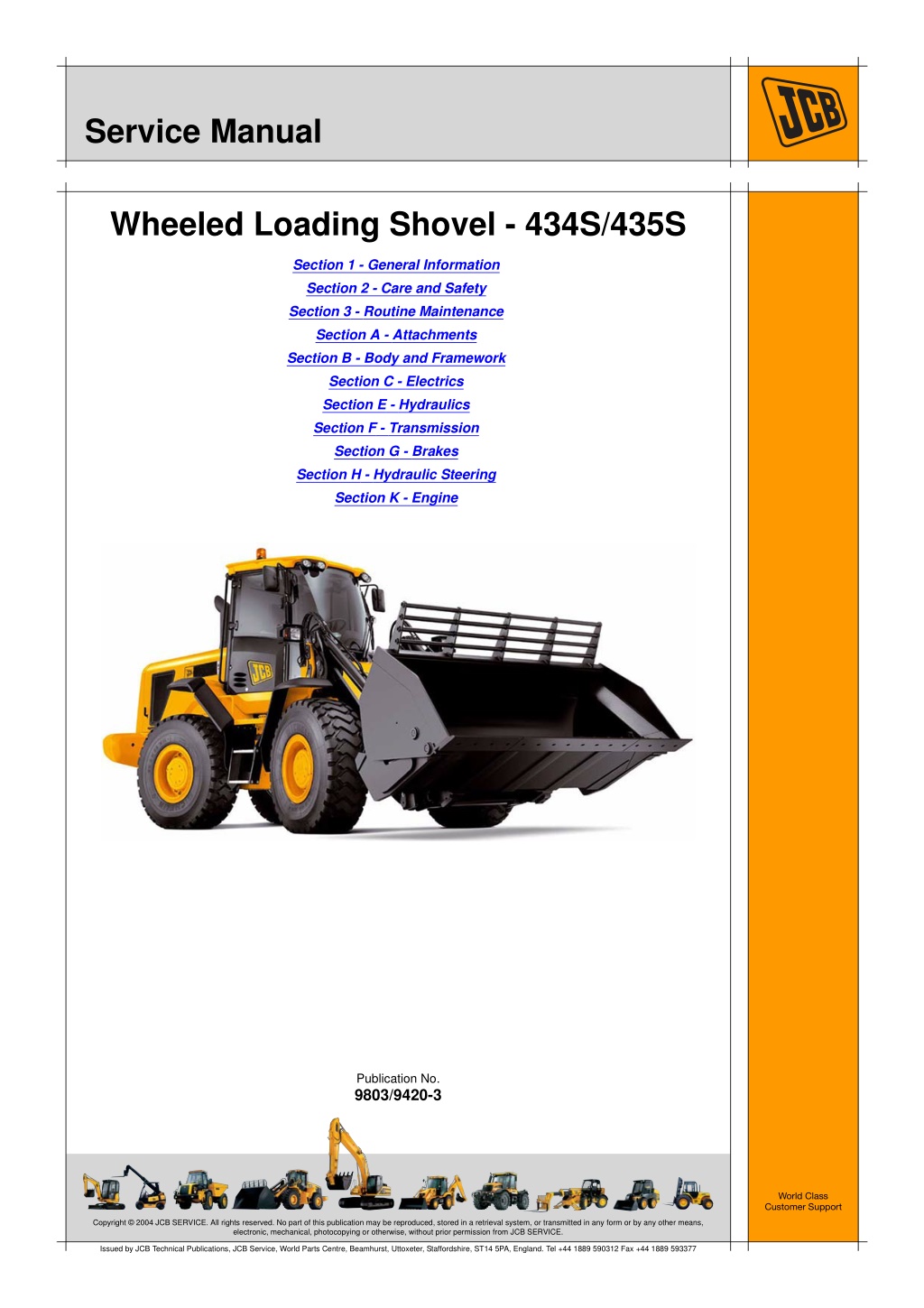
Service Manual Wheeled Loading Shovel - 434S/435S Section 1 - General Information Section 2 - Care and Safety Section 3 - Routine Maintenance Section A - Attachments Section B - Body and Framework Section C - Electrics Section E - Hydraulics Section F - Transmission Section G - Brakes Section H - Hydraulic Steering Section K - Engine Publication No. 9803/9420-3 World Class Customer Support Copyright 2004 JCB SERVICE. All rights reserved. No part of this publication may be reproduced, stored in a retrieval system, or transmitted in any form or by any other means, electronic, mechanical, photocopying or otherwise, without prior permission from JCB SERVICE. Issued by JCB Technical Publications, JCB Service, World Parts Centre, Beamhurst, Uttoxeter, Staffordshire, ST14 5PA, England. Tel +44 1889 590312 Fax +44 1889 593377
Section 1 General Information Section 1 - General Information Section 2 - Care and Safety Section 3a - Routine Maintenance Section 3b - Routine Maintenance Section A - Attachments Section B - Body and Framework Section C - Electrics Section E - Hydraulics Section F - Transmission Section G - Brakes Section H - Hydraulic Steering Section K - Engine Publication No. 9803/9420-3 World Class Customer Support Copyright 2004 JCB SERVICE. All rights reserved. No part of this publication may be reproduced, stored in a retrieval system, or transmitted in any form or by any other means, electronic, mechanical, photocopying or otherwise, without prior permission from JCB SERVICE. Issued by JCB Technical Publications, JCB Service, World Parts Centre, Beamhurst, Uttoxeter, Staffordshire, ST14 5PA, England. Tel +44 1889 590312 Fax +44 1889 593377
Section 1 - General Information Contents Introduction About this Publication .............................................................................. 1 - 1 Page No. Identifying your Machine 434S ........................................................................................................ 1 - 5 435S ........................................................................................................ 1 - 8 Torque Settings Zinc Plated Fasteners and Dacromet Fasteners ..................................... 1 - 9 Hydraulic Connections ........................................................................... 1 - 13 Service Tools Numerical List ........................................................................................ 1 - 17 Tool Detail Reference ............................................................................ 1 - 18 Service Consumables Sealing and Retaining Compounds ....................................................... 1 - 37 Terms and Definitions Colour Coding ........................................................................................ 1 - 39 1 - i 1 - i
https://www.ebooklibonline.com Hello dear friend! Thank you very much for reading. Enter the link into your browser. The full manual is available for immediate download. https://www.ebooklibonline.com
Section 1 - General Information Introduction About this Publication Machine Model and Serial Number Finally, please remember above all else safety must come first! This manual provides information for the following model(s) in the JCB machine range: Section Numbering T11-005 434S From machine 1244000 The manual is compiled in sections, the first three are numbered and contain information as follows: 435S: From 2063353 to 2063382. 1 General Information - includes torque settings and service tools. Using the Service Manual T11-004 2 Care and Safety - includes warnings and cautions pertinent to aspects of workshop procedures etc. This publication is designed for the benefit of JCB Distributor Service Engineers who are receiving, or have received, training by JCB Technical Training Department. 3 Maintenance - includes service schedules and recommended lubricants for all the machine. These personnel should have a sound knowledge of workshop practice, safety procedures, and general techniques associated with the maintenance and repair of hydraulic earthmoving equipment. The remaining sections are alphabetically coded and deal with Dismantling, Overhaul etc. of specific components, for example: The illustrations in this publication are for guidance only. Where the machines differ, the text and/or the illustration will specify. A Attachments B Body and Framework, etc. General warnings in Section 2 are repeated throughout the manual, as well as specific warnings. Read all safety statements regularly, so you do not forget them. Section contents, technical data, circuit descriptions, operation descriptions etc. are inserted at the beginning of each alphabetically coded section. Renewal of oil seals, gaskets, etc., and any component showing obvious signs of wear or damage is expected as a matter of course. It is expected that components will be cleaned and lubricated where appropriate, and that any opened hose or pipe connections will be blanked to prevent excessive loss of hydraulic fluid and ingress of dirt. Where a torque setting is given as a single figure it may be varied by plus or minus 3%. Torque figures indicated are for dry threads, hence for lubricated threads may be reduced by one third. The manufacturer's policy is one of continuous improvement. The right to change the specification of the machine without notice is reserved. No responsibility will be accepted for discrepancies which may occur between specifications of the machine and the descriptions contained in this publication. 1 - 1 1 - 1 9803/9420
Section 1 - General Information Introduction About this Publication Left Side, Right Side 9A Tool box (434S) 9B Tool box (435S) In this manual, 'left' A and 'right' B mean your left and right when you are seated correctly in the machine. 10 Battery isolator switch 11 Rear grille 12 Coolant filler cap 13 Air filter assembly 14 Hydraulic fluid filter 15 Fuel filter - suction side 16 Hydraulic fluid filler cap 17 Fuel filter - pressure side 18 Engine oil dipstick 19 Engine oil filler cap T033800-1 20 Exhaust Fig 1. 21 Radiator Cab/Canopy 22 Diesel filler point T1-003_2 23 Engine oil filter This manual frequently makes references to the cab. For instance, 'do not operate the machine without a manual in the cab'. It should be noted that these statements also apply to canopy build machines. 24 Transmission oil dipstick/filler point 25 Coolant header tank Cross References T1-004_2 In this publication, page cross references are made by presenting the subject title printed in bold, italic and underlined. It is preceeded by the 'go to' symbol. The number of the page upon which the subject begins, is indicated within the brackets. For example: K References ( T T 1-2). K Cross Component Location Note: The illustration(s) show a typical machine model; your machine may look different from the model shown. For example, the 435S has a diesel particulate filter. 1 Shovel 2 Loader arms 3 Beacon 4 ROPS/FOPS cab 5 Engine cover 6 Articulation lock 7 Heater door 8 Hydraulic fluid level - sight glass 1 - 2 1 - 2 9803/9420
Section 1 - General Information Introduction About this Publication 3 4 2 5 1 12 7 A 6 8 9B 11 10 9A 13 14 15 17 16 19 18 20 25 24 21 23 22 T066060-10A Fig 2. 1 - 3 1 - 3 9803/9420
Section 1 - General Information Identifying your Machine 434S Identification Plate The machine and engine serial numbers can help identify exactly the type of equipment you have. Your machine has an identification plate 3X mounted on the left hand side of the machine. The serial numbers of the machine and its major units are stamped on the plate. Unit Identification The engine serial number is stamped on a plate 4Y which is fastened to the right side of the cylinder block, near the fuel filter. Fig 3. Explanation of Vehicle Identification Number (VIN) 1 2 3 4 5 SLP 43400 6 E 1244000 Fig 4. 1 World Manufacturer Identification, SLP = JCB 2 Machine Model, 43400 = 434 3 Year of Manufacture 6, ( W = 1998, X = 1999, Y = 2000, 1 = 2001, 2 = 2002, 3 = 2003, 4 = 2004, 5 = 2005, 6 = 2006, 7 = 2007, etc.) 4 Manufacturing Location (E = England) 5 Machine Serial Number (1244000) The serial number of each major unit is also stamped on the unit itself. If a major unit is replaced by a new one, the serial number on the identification plate will be wrong. Either stamp the new number of the unit on the identification plate, or simply stamp out the old number. This will prevent the wrong unit number being quoted when replacement parts are ordered. 1 - 5 1 - 5 9803/9420
Section 1 - General Information Identifying your Machine 434S Typical Engine Identification Number 1 2 3 4 5 YB 50457 U 576887 6 1 Engine Type, YB = 6 cylinder turbo 2 Build Number 3 Country of Origin 4 Engine Sequence Number 5 Year of Manufacture The Transmission serial number is stamped on plate 5Z as shown. Fig 5. 1 - 6 1 - 6 9803/9420
Section 1 - General Information Identifying your Machine 434S Component Identification Plates ROPS Data Plate !MWARNING FOPS Data Plate Seat Belts !MWARNING The ROPS/FOPS is designed to give you protection in an accident. If you do not wear your seat belt, you could be thrown out of the machine and crushed. You must wear a seat belt when using the machine. Fasten the seat belt before starting the engine. Do not use the machine if the falling objects protection level provided by the structure is not sufficient for the application. Falling objects can cause serious injury. 8-2-8-17 0153 If the machine is used in any application where there is a risk of falling objects then a falling-objects protective structure (FOPS) must be installed. For further information contact your JCB Dealer Machines built to the ROPS/FOPS standard have a data plate attached to the inside of the cab. The falling objects protection structure (FOPS) is fitted with a dataplate. The dataplate indicates what level protection the structure provides. FOPS: COMPLIES TO EN 13627: 2000 LEVEL2 ROPS: COMPLIES TO EN 13510: 2000 ISO 3471:1994 427, 437, JCB WHEELED LOADER J.C.B. CAB SYSTEMS LAKESIDE WORKS ROCESTER UTTOXETER, STAFFS ST14 5JP ENGLAND MAXIMUM UNLADEN MASS 26000Kg YEAR: There are two levels of FOPS: CAB PART No: 335/06840, 335/09298 SERIAL No: 332/A5586 Level I Impact Protection - impact strength for protection from small falling objects (e.g. bricks, small concrete blocks, hand tools) encountered in operations such as landscaping and other construction site services. Level II Impact Protection - impact strength for protection from heavy falling objects (e.g. trees, rocks) for machines involved in site clearing, overhead demolition or forestry. 332-A5586-1 Fig 6. Example highway maintenance, 1 - 7 1 - 7 9803/9420
Section 1 - General Information Identifying your Machine 435S 435S Machine Identification Plate Typical Product Identification Number Your machine has an identification plate mounted as shown. The serial numbers of the machine and its major units are stamped on the plate. 1 2 3 4 5 6 JCB 435S Z O C 2063353 Note: The machine model and build specification is indicated by the PIN. Refer to Typical Product Identification Number (PIN). 1 World Manufacturer Identification (3 Digits) 2 Model Number (3 Digits) The serial number of each major unit is also stamped on the unit itself. If a major unit is replaced by a new one, the serial number on the identification plate will be wrong. Either stamp the new number of the unit on the identification plate, or simply stamp out the old number. This will prevent the wrong unit number being quoted when replacement parts are ordered. 3 Loader End Type (1 Digit) O = HT Loader End Z = ZX Loader End 4 Designation (1 Digit) The machine and engine serial numbers can help identify exactly the type of equipment you have. S = Farmmaster O = Non Farmmaster I = India 5 Year of Manufacture (1 Digit) 7 = 2007 A = 2010 8 = 2008 B = 2011 9 = 2009 C = 2012 6 Machine Serial Number (8 Digits) Each machine has a unique serial number. T033550-2 Fig 7. 1 - 8 1 - 8 9803/9420
Section 1 - General Information Torque Settings Zinc Plated Fasteners and Dacromet Fasteners Torque Settings Zinc Plated Fasteners and Dacromet Fasteners T11-002 Introduction Bolts and Screws Some external fasteners on JCB machines are manufactured using an improved type of corrosion resistant finish. This type of finish is called Dacromet and replaces the original Zinc and Yellow Plating used on earlier machines. Use the following torque setting tables only where no torque setting is specified in the text. Note: Dacromet fasteners are lubricated as part of the plating process, do not lubricate. The two types of fasteners can be readily identified by colour and part number suffix. K ( T T 1-9). Torque settings are given for the following conditions: K Table 1. Fastener Types Condition 1 Table 1. Fastener Types Colour Un-lubricated fasteners Zinc fasteners Yellow plated fasteners Fastener Type Part No. Suffix Zinc and Yellow Golden finish 'Z' (e.g. 1315/3712Z) Condition 2 Dacromet Mottled silver finish 'D' (e.g. 1315/3712D) Zinc flake (Dacromet) fasteners Lubricated zinc and yellow plated fasteners Where there is a natural lubrication. For example, cast iron components Note: As the Dacromet fasteners have a lower torque setting than the Zinc and Yellow fasteners, the torque figures used must be relevant to the type of fastener. Note: A Dacromet bolt should not be used in conjunction with a Zinc or Yellow plated nut, as this could change the torque characteristics of the torque setting further. For the same reason, a Dacromet nut should not be used with a Zinc or Yellow plated bolt. Verbus Ripp Bolts Note: All bolts used on JCB machines are high tensile and must not be replaced by bolts of a lesser tensile specification. Fig 8. Note: Dacromet bolts, due to their high corrosion resistance are used in areas where rust could occur. Dacromet bolts are only used for external applications. They are not used in applications such as gearbox or engine joint seams or internal applications. Torque settings for these bolts are determined by the application. Refer to the relevant procedure for the required settings. 1 - 9 1 - 9 9803/9420
Section 1 - General Information Torque Settings Zinc Plated Fasteners and Dacromet Fasteners Table 2. Torque Settings - UNF Grade 'S' Fasteners Hexagon (A/F) Bolt Size Condition 1 Condition 2 in. mm in. Nm kgf m lbf ft Nm kgf m lbf ft 1/4 6.3 7/16 11.2 1.1 8.3 10.0 1.0 7.4 5/16 7.9 1/2 22.3 2.3 16.4 20.0 2.0 14.7 3/8 9.5 9/16 40.0 4.1 29.5 36.0 3.7 26.5 7/16 11.1 5/8 64.0 6.5 47.2 57.0 5.8 42.0 1/2 12.7 3/4 98.00 10.0 72.3 88.0 9.0 64.9 9/16 14.3 13/16 140.0 14.3 103.2 126.0 12.8 92.9 5/8 15.9 15/16 196.0 20.0 144.6 177.0 18.0 130.5 3/4 19.0 1 1/8 343.0 35.0 253.0 309.0 31.5 227.9 7/8 22.2 1 15/16 547.0 55.8 403.4 492.0 50.2 362.9 1 25.4 1 1/2 814.0 83.0 600.4 732.0 74.6 539.9 1 1/8 31.7 1 7/8 1181.0 120.4 871.1 1063.0 108.4 784.0 1 1/4 38.1 2 1/4 1646.0 167.8 1214.0 1481.0 151.0 1092.3 Table 3. Torque Settings - Metric Grade 8.8 Fasteners Hexagon (A/F) Bolt Size Condition 1 Condition 2 ISO Metric Thread mm mm Nm kgf m lbf ft Nm kgf m lbf ft M5 5 8 5.8 0.6 4.3 5.2 0.5 3.8 M6 6 10 9.9 1.0 7.3 9.0 0.9 6.6 M8 8 13 24.0 2.4 17.7 22.0 2.2 16.2 M10 10 17 47.0 4.8 34.7 43.0 4.4 31.7 M12 12 19 83.0 8.5 61.2 74.0 7.5 54.6 M16 16 24 205.0 20.9 151.2 184.0 18.8 135.7 M20 20 30 400.0 40.8 295.0 360.0 36.7 265.5 M24 24 36 690.0 70.4 508.9 621.0 63.3 458.0 M30 30 46 1372.0 139.9 1011.9 1235.0 125.9 910.9 M36 36 55 2399.0 244.6 1769.4 2159.0 220.0 1592.4 1 - 10 1 - 10 9803/9420
Section 1 - General Information Torque Settings Zinc Plated Fasteners and Dacromet Fasteners Table 4. Metric Grade 10.9 Fasteners Hexagon (A/F) Bolt Size Condition 1 Condition 2 ISO Metric Thread mm mm Nm kgf m lbf ft Nm kgf m lbf ft M5 5 8 8.1 0.8 6.0 7.3 0.7 5.4 M6 6 10 13.9 1.4 10.2 12.5 1.3 9.2 M8 8 13 34.0 3.5 25.0 30.0 3.0 22.1 M10 10 17 67.0 6.8 49.4 60.0 6.1 44.2 M12 12 19 116.0 11.8 85.5 104.0 10.6 76.7 M16 16 24 288.0 29.4 212.4 259.0 26.4 191.0 M20 20 30 562.0 57.3 414.5 506.0 51.6 373.2 M24 24 36 971.0 99.0 716.9 874.0 89.1 644.6 M30 30 46 1930.0 196.8 1423.5 1737.0 177.1 1281.1 M36 36 55 3374.0 344.0 2488.5 3036.0 309.6 2239.2 Table 5. Metric Grade 12.9 Fasteners Hexagon (A/F) Bolt Size Condition 1 Condition 2 ISO Metric Thread mm mm Nm kgf m lbf ft Nm kgf m lbf ft M5 5 8 9.8 1.0 7.2 8.8 0.9 6.5 M6 6 10 16.6 1.7 12.2 15.0 1.5 11.1 M8 8 13 40.0 4.1 29.5 36.0 3.7 26.5 M10 10 17 80.0 8.1 59.0 72.0 7.3 53.1 M12 12 19 139.0 14.2 102.5 125.0 12.7 92.2 M16 16 24 345.0 35.2 254.4 311.0 31.7 229.4 M20 20 30 674.0 68.7 497.1 607.0 61.9 447.7 M24 24 36 1165.0 118.8 859.2 1048.0 106.9 773.0 M30 30 46 2316.0 236.2 1708.2 2084.0 212.5 1537.1 M36 36 55 4049.0 412.9 2986.4 3644.0 371.6 2687.7 1 - 11 1 - 11 9803/9420
Section 1 - General Information Torque Settings Zinc Plated Fasteners and Dacromet Fasteners Table 6. Torque Settings - Rivet Nut Bolts/Screws Bolt Size ISO Metric Thread mm Nm kgf m lbf ft M3 3 1.2 0.1 0.9 M4 4 3.0 0.3 2.0 M5 5 6.0 0.6 4.5 M6 6 10.0 1.0 7.5 M8 8 24.0 2.5 18.0 M10 10 48.0 4.9 35.5 M12 12 82.0 8.4 60.5 Table 7. Torque Settings - Internal Hexagon Headed Cap Screws (Zinc) Bolt Size ISO Metric Thread Nm kgf m lbf ft M3 2.0 0.2 1.5 M4 6.0 0.6 4.5 M5 11.0 1.1 8.0 M6 19.0 1.9 14.0 M8 46.0 4.7 34.0 M10 91.0 9.3 67.0 M12 159.0 16.2 117.0 M16 395.0 40.0 292.0 M18 550.0 56.0 406.0 M20 770.0 79.0 568.0 M24 1332.0 136.0 983.0 1 - 12 1 - 12 9803/9420
Section 1 - General Information Torque Settings Hydraulic Connections Hydraulic Connections T11-003 'O' Ring Face Seal System Adaptors Screwed into Valve Blocks Adaptor screwed into valve blocks, seal onto an 'O' ring which is compressed into a 45 seat machined into the face of the tapped port. Table 8. Torque Settings - BSP Adaptors BSP Adaptor Size Hexagon (A/F) in. mm Nm kgf m lbf ft 1/4 19.0 18.0 1.8 13.0 3/8 22.0 31.0 3.2 23.0 1/2 27.0 49.0 5.0 36.0 5/8 30.0 60.0 6.1 44.0 3/4 32.0 81.0 8.2 60.0 1 38.0 129.0 13.1 95.0 1 1/4 50.0 206.0 21.0 152.0 Table 9. Torque Settings - SAE Connections Hexagon (A/F) SAE Tube Size SAE Port Thread Size mm Nm kgf m lbf ft 4 7/16 - 20 15.9 20.0 - 28.0 2.0 - 2.8 16.5 - 18.5 6 9/16 - 18 19.1 46.0 - 54.0 4.7 - 5.5 34.0 - 40.0 8 3/4 - 16 22.2 95.0 - 105.0 9.7 - 10.7 69.0 - 77.0 10 7/8 - 14 27.0 130.0 - 140.0 13.2 - 14.3 96.0 - 104.0 12 1 1/16 - 12 31.8 190.0 - 210.0 19.4 - 21.4 141.0 - 155.0 16 1 5/16 - 12 38.1 290.0 - 310.0 29.6 - 31.6 216.0 - 230.0 20 1 5/8 47.6 280.0 - 380.0 28.5 - 38.7 210.0 - 280.0 1 - 13 1 - 13 9803/9420
Section 1 - General Information Torque Settings Hydraulic Connections Hoses Screwed into Adaptors Fig 9. Hoses 9-B screwed into adaptors 9-A seal onto an `O' ring 9-C which is compressed into a 45 seat machined into the face of the adaptor port. Note: Dimension 9-D will vary depending upon the torque applied. Table 10. BSP Hose - Torque Settings Hexagon (A/F) BSP Hose Size in. mm Nm kgf m lbf ft 1/8 14.0 14.0 - 16.00 1.4 - 1.6 10.3 - 11.8 1/4 19.0 24.0 - 27.0 2.4 - 2.7 17.7 - 19.9 3/8 22.0 33.0 - 40.0 3.4 - 4.1 24.3 - 29.5 1/2 27.0 44.0 - 50.0 4.5 - 5.1 32.4 - 36.9 5/8 30.0 58.0 - 65.0 5.9 - 6.6 42.8 - 47.9 3/4 32.0 84.0 - 92.0 8.6 - 9.4 61.9 - 67.8 1 38.0 115.0 - 126.0 11.7 - 12.8 84.8 - 92.9 1 1/4 50.0 189.0 - 200.0 19.3 - 20.4 139.4 - 147.5 1 1/2 55.0 244.0 - 260.0 24.9 - 26.5 180.0 - 191.8 1 - 14 1 - 14 9803/9420
Section 1 - General Information Torque Settings Hydraulic Connections Adaptors into Component Connections with Bonded Washers Table 11. BSP Adaptors with Bonded Washers - Torque Settings BSP Size in. Nm kgf m lbf ft 1/8 20.0 2.1 15.0 1/4 34.0 3.4 25.0 3/8 75.0 7.6 55.0 1/2 102.0 10.3 75.0 5/8 122.0 12.4 90.0 3/4 183.0 18.7 135.0 1 203.0 20.7 150.0 1 1/4 305.0 31.0 225.0 1 1/2 305.0 31.0 225.0 1 - 15 1 - 15 9803/9420
Section 1 - General Information Torque Settings Hydraulic Connections 'Torque Stop' Hose System Fig 10. `Torque Stop' Hoses 10-B screwed into adaptors 10-A seal onto an 'O' ring 10-C which is compressed into a 45 seat machined in the face of the adaptor port. To prevent the 'O' ring being damages as a result of over tightening, 'Torque Stop' Hoses have an additional shoulder 10-D, which acts as a physical stop. Note: Minimum dimension 10-E fixed by shoulder 10-D. Table 12. BSP `Torque Stop' Hose - Torque Settings BSP Hose Size Hexagon (A/F) in. mm Nm kgf m lbf ft 1/8 14.0 14.0 1.4 10.0 1/4 19.0 27.0 2.7 20.0 3/8 22.0 40.0 4.1 30.0 1/2 27.0 55.0 5.6 40.0 5/8 30.0 65.0 6.6 48.0 3/4 32.0 95.0 9.7 70.0 1 38.0 120.0 12.2 89.0 1 1/4 50.0 189.0 19.3 140.0 1 1/2 55.0 244.0 24.9 180.0 1 - 16 1 - 16 9803/9420
Section 2 Care and Safety Section 1 - General Information Section 2 - Care and Safety Section 3a - Routine Maintenance Section 3b - Routine Maintenance Section A - Attachments Section B - Body and Framework Section C - Electrics Section E - Hydraulics Section F - Transmission Section G - Brakes Section H - Hydraulic Steering Section K - Engine Publication No. 9803/9420-3 World Class Customer Support Copyright 2004 JCB SERVICE. All rights reserved. No part of this publication may be reproduced, stored in a retrieval system, or transmitted in any form or by any other means, electronic, mechanical, photocopying or otherwise, without prior permission from JCB SERVICE. Issued by JCB Technical Publications, JCB Service, World Parts Centre, Beamhurst, Uttoxeter, Staffordshire, ST14 5PA, England. Tel +44 1889 590312 Fax +44 1889 593377
Section 2 - Care and Safety Contents Safety Notices Safety Check List ..................................................................................... 2 - 1 Safety - Yours and Others .................................................................. 2 - 1 General Safety ................................................................................... 2 - 1 Operating Safety ................................................................................ 2 - 3 Maintenance Safety ............................................................................ 2 - 6 Safety Labels ......................................................................................... 2 - 11 Introduction ....................................................................................... 2 - 11 Safety Label Identification ................................................................ 2 - 12 Part Numbers and Descriptions ....................................................... 2 - 13 Page No. 2 - i 2 - i
Suggest: If the above button click is invalid. Please download this document first, and then click the above link to download the complete manual. Thank you so much for reading
Section 2 - Care and Safety Safety Notices Safety Check List P4-1004_3 Safety - Yours and Others General Safety INT-1-3-1_3 T1-043 !MWARNING All machinery can be hazardous. When a machine is correctly operated and properly maintained, it is a safe machine to work with. But when it is carelessly operated or poorly maintained it can become a danger to you (the operator) and others. To operate the machine safely you must know the machine and have the skill to use it. You must abide by all relevant laws, health and safety regulations that apply to the country you are operating in. The Operator Manual instructs you on the machine, its controls and its safe operation; it is not a training manual. If you are a new operator, get yourself trained in the skills of using a machine before trying to work with it. If you don't, you will not do your job well, and you will be a danger to yourself and others. In this manual and on the machine you will find warning messages. Read and understand them. They tell you of potential hazards and how to avoid them. If you do not fully understand the warning messages, ask your employer or JCB distributor to explain them. But safety is not just a matter of responding to the warnings. All the time you are working on or with the machine you must be thinking what hazards there might be and how to avoid them. INT-1-4-1 !MWARNING Care and Alertness Do not work with the machine until you are sure that you can control it. All the time you are working with or on the machine, take care and stay alert. Always be careful. Always be alert for hazards. Do not start any job until you are sure that you and those around you will be safe. INT-1-3-5 !MWARNING If you are unsure of anything, about the machine or the job, ask someone who knows. Do not assume anything. Clothing You can be injured if you do not wear the proper clothing. Loose clothing can get caught in the machinery. Wear protective clothing to suit the job. Examples of protective clothing are: a hard hat, safety shoes, safety glasses, a well fitting overall, ear- protectors and industrial gloves. Keep cuffs fastened. Do not wear a necktie or scarf. Keep long hair restrained. Remove rings, watches and personal jewellery. Remember BE CAREFUL BE ALERT BE SAFE INT-1-3-6_2 2 - 1 2 - 1 9803/9420
Section 2 - Care and Safety Safety Notices Safety Check List !MWARNING !MWARNING Alcohol and Drugs Raised Machine It is extremely dangerous to operate machinery when under the influence of alcohol or drugs. Do not consume alcoholic drinks or take drugs before or while operating the machine or attachments. Be aware of medicines which can cause drowsiness. NEVER position yourself or any part of your body under a raised machine which is not properly supported. If the machine moves unexpectedly you could become trapped and suffer serious injury or be killed. INT-1-3-9_2 INT-3-3-7_1 !MWARNING !MDANGER Feeling Unwell Lightning Do not attempt to operate the machine if you are feeling unwell. By doing so you could be a danger to yourself and those you work with. Lightning can kill you. Do not use the machine if there is lightning in your area. 5-1-1-2 8-1-2-4 !MWARNING !MWARNING Machine Modifications Mobile Phones This machine is manufactured in compliance with legislative and other requirements. It should not be altered in any way which could affect or invalidate any of these requirements. For advice consult your JCB Distributor. Switch off your mobile phone before entering an area with a potentially explosive atmosphere. Sparks in such an area could cause an explosion or fire resulting in death or serious injury. INT-1-3-10_2 Switch off and do not use your mobile phone when refuelling the machine. INT-3-3-9 !MWARNING Lifting Equipment You can be injured if you use incorrect or faulty lifting equipment. You must identify the weight of the item to be lifted then choose lifting equipment that is strong enough and suitable for the job. Make sure that lifting equipment is in good condition and complies with all local regulations. INT-1-3-7_2 !MWARNING Raised Equipment Never walk or work under raised equipment unless it is supported by a mechanical device. Equipment which is supported only by a hydraulic device can drop and injure you if the hydraulic system fails or if the control is operated (even with the engine stopped). Make sure that no-one goes near the machine while you install or remove the mechanical device. 13-2-3-7_3 2 - 2 2 - 2 9803/9420
https://www.ebooklibonline.com Hello dear friend! Thank you very much for reading. Enter the link into your browser. The full manual is available for immediate download. https://www.ebooklibonline.com