Understanding CNC Machine Tools: Fundamentals and Advantages


Part #3
CNC Machine Tools
Outline:
•
Introduction - CNC definition
•
Major features of CNC M/c tools
•
Classifications of CNC M/c tools
•
Major components of CNC system
CNC
is the process of manufacturing
machined parts
.
This process is
controlled
by a
computerized controller
called
Machine Control Unit (MCU).
The
MCU
generates, stores
and
processes
CNC
programs
.
The
MCU
uses
motors
to
drive each axis
of a machine and
regulates
its
direction, speed
, and the
amount of time each
motor rotates
.
1.
Fundamentals of CNC M/C Tools
1.1.
Computer Numerical Control (CNC) – Defn.
Cont’d…
•
CNC
can
also be
defined
as a
programmable automation
in which
the
mechanical actions
of a
‘machine tool
’ are controlled by
a
program
containing
coded alphanumeric data
that represents relative
positions between
a work head
(e.g., cutting tool) and
a work part
.
Fig. 1. CNC System
Cont’d…
1.2.
Major Features of CNC Machine Tools
Storage of more than one part program
Various forms of program input
Program editing at the machine tool
Fixed cycles and programming subroutines
Interpolation
Cutter length & size compensations
Acceleration and deceleration computations
Communications interface
Diagnostics
1.3.
When it is appropriate to use NC/CNC system?
1)
Parts from similar raw materials, in a
variety of sizes
and
/or
complex shapes.
2)
Low to medium
part production.
3)
Similar processing operations and sequences among work
pieces.
4)
Meet
tight tolerance & accuracy
requirements compared
to similar conventional machines.
1.4.
Advantages of CNC over conventional Machine Tools
>
Flexibility with accuracy & repeatability,
reduced scraps, high production rates, good quality
>
Reduced tooling costs
>
Easy machine adjustments
>
More operations per set up
>
Less lead time
>
Accommodate design changes
>
Less skilled operator
1.5.
What is DNC?
•
Direct numerical control (DNC)
– control of
multiple machine tools
by a
single (mainframe) computer
through
direct connection
and in real
time.
Central computer
stores programs
&
directs NC operations
;
NC
m/cs
are
dependent on central computer
.
1960s technology
two way communication
•
Distributed numerical control (DNC)
– network consisting of
central
computer
connected to
machine tool MCUs,
which are CNC. Central
computer
stores the program
&
distribute it
to the CNC machines.
present technology
two way communication
Cont’d…
Fig. DNC System
2.
Classification of CNC Machine Tools
1.
Based on Motion Type
i.
Point to point systems
Require the
cutter
and the
work piece
to be placed at a
certain fixed
relative positions
at which they must
remain
while the
cutter does its work
.
Each axis
is
driven separately.
Dimensional information
that must be given to the machine tool will be a
series of required position
of the two slides.
Servo systems
can be used to
move the slides
and
no attempt
is made to
move
the slide until the cutter has been
retracted back.
Examples
are
drilling, boring
and
tapping machines…
etc.
ii.
Contouring systems (Continuous path systems)
Involves
motion of work piece with respect to the cutter
while
cutting
operation is taking place.
Contouring machines
can also be used as
point-to-point machines,
but
it will
be
uneconomical
to use them unless the work piece also requires having a
contouring operation
to be performed on it.
Cont’d…
These machines require
simultaneous control of axes.
Relative positions
of the work
piece and the tool should be
continuously controlled
.
The
control system
must be able to
accept information regarding
velocities
and
positions
of the
machines slides
and
feed rates
should be programmed.
Examples
are
milling,
routing machines etc
.
Cont’d….
2.
Based on the Control loops
1.
Open loop systems
Programmed instructions
are fed into the
controller
through an
input device.
These
instructions
are then
converted to electrical pulses (signals)
by the
controller
and
sent to the servo amplifier
to
energize
the
servo motors.
If the
system performance
is affected by
load, temperature, humidity, or
lubrication
then the
actual output
could deviate from the
desired output.
Generally the
open - loop system
is used in
point-to-point systems
where the
accuracy requirements
are
not critical.
2.2.
Closed loop systems
The
closed-loop system
has a
feedback subsystem
to
monitor the
actual output
and
correct any discrepancy
from the
programmed
input.
These systems
use position
and
velocity feedback
and the feedback
system could be either
analog or digital.
The
analog systems
measure the
variation of physical variables
such as
position
and
velocity
in terms of
voltage levels.
Digital systems
monitor
output variations
by means of
electrical
pulses.
To control the
dynamic behavior
and the
final position of
the
machine
slides
, a
variety of position transducers
are employed.
Cont’d….
If
a discrepancy
is revealed between where the
machine element should be
and
where it actually is
, the
sensing device
signals the
driving unit
to make an
adjustment
, bringing the
movable component
to the
required location.
Cont’d….
3.
Based on the number of axes
a)
2 & 3 Axes CNC machines
CNC lathes
will be coming under
2 axes machines.
There will be
two axes
along which
motion
takes
place. The
saddle
will be moving
longitudinally on
the bed (Z-axis)
and the
cross slide
moves
transversely
on the saddle (along X-axis).
In
3-axes machines
, there will be one more axis,
perpendicular to the above
two axes.
Ex
. CNC milling
machine
b)
4 & 5 axes CNC machines
A
5-axis milling centre
includes the three
X, Y, Z
axes, the
A axis
which is
rotary tilting of the
spindle
and the
B-axis,
which can be
a
rotary index
table.
Cont’d….
Reduced cycle time
by machining
complex components
using
a single
setup
. In addition to
time savings,
improved accuracy
can also be achieved as
positioning errors between setups are eliminated.
Improved surface finish
and
tool life
by
tilting the tool
to maintain
optimum tool to part contact
all the times.
Higher axes machining
has been widely used for
machining sculptures
surfaces
in aerospace and automobile industry.
4.
Based on the Power Supply
1.
Mechanical systems
Mechanical power unit
refers to
a device
which transforms some
form of energy
to
mechanical power
which may be used for
driving slides, saddles
or
gantries
forming a part of machine tool.
2.
Electric systems
Electric motors
may be used for
controlling both positioning
and
contouring
machines
.
They may be either
a.c. or d.c. motor
and the
torque
and
direction of
rotation
need to be controlled. The
speed of a d.c. motor
can be controlled by varying
either the
field or the armature supply.
3.
Hydraulic systems
These
hydraulic systems
may be used with
positioning and contouring machine
tools
of all sizes. These systems may be either in the form of
rams or motors.
Hydraulic motors
are smaller than
electric motors
of equivalent power.
3.
MAJOR COMPONENTS OF A CNC SYSTEM
1.
Different components related to CNC machine tools
1.1.
Part program
A
part program
is a
series of coded instructions
required to produce a part.
It controls the
movement of the machine tool
and
on/off control
of
auxiliary functions
such as spindle rotation and coolant.
The
coded instructions
are composed of
letters, numbers and symbols.
1.2.
Program input device
The
program input device
is the
means for part program
to be entered into
the
CNC control.
Commonly
used program input devices are
punch tape reader, magnetic tape
reader, floppy diskettes
and
computer via RS-232-C communication.
1.3.
Machine Control Unit
MCU
is the
heart of a CNC system.
It is used to
perform the following
functions:
To
read
the coded instructions.
To
decode
the coded instructions.
To
implement interpolations
(linear, circular,
and helical) to generate axis motion commands.
To
feed the axis motion commands
to the
amplifier circuits for driving the axis
mechanisms.
To
receive the feedback signals
of position and
speed for each drive axis.
To
implement auxiliary control functions
such
as coolant or spindle on/off and tool change.
Cont’d….
1.4.
Drive System
A
drive system
consists of
amplifier circuits, drive motors
, and
ball lead-screws.
The
MCU
feeds the
control signals (position and speed)
of each axis to the
amplifier circuits.
The
control signals
are
augmented
to
actuate drive motors
which
in turn
rotate the ball lead-screws
to
position the machine table.
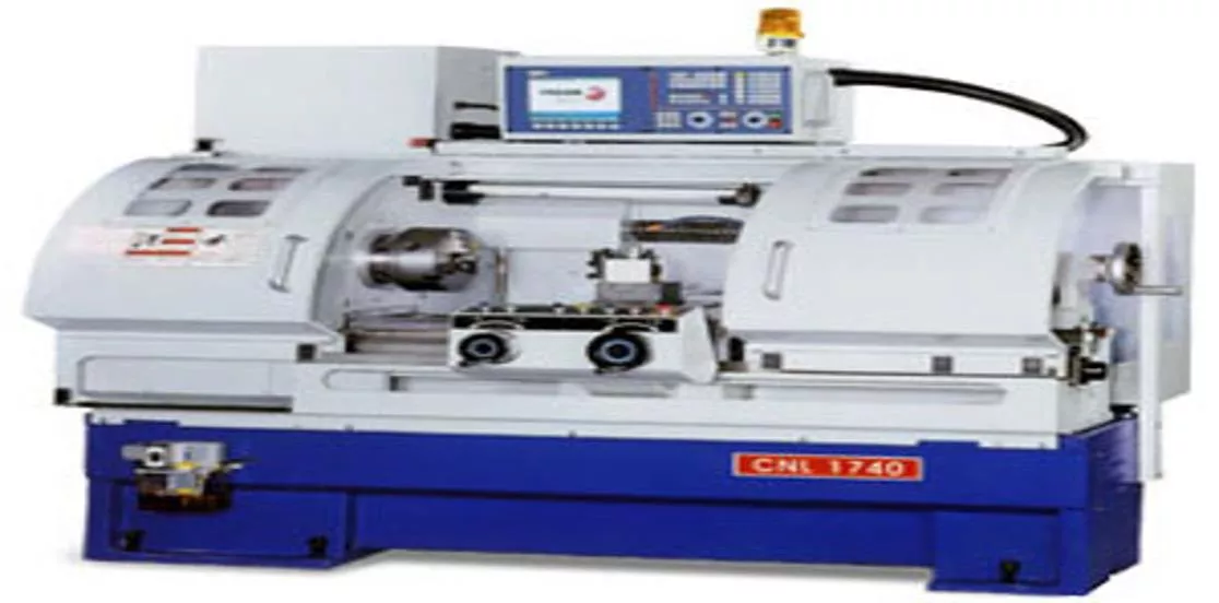
1.5.
Machine Tool
CNC controls
are used
to control various types
of machine tools. Regardless of which
type of machine tool is controlled, it always has
a slide table
and
a spindle
to control of
position and speed.
The
machine table
is controlled in the
X and Y axes,
while the
spindle
runs along
the
Z axis.
Cont’d….
1.6.
Feed Back System
It uses
position
and
speed transducers
to continuously
monitor
the position at which the
cutting tool
is located at any
particular instant.
The
MCU
uses the difference between
reference signals
and
feedback signals
to generate the
control signals
for
correcting position
and
speed errors.
Cont’d….
2:
Machine axes designation
Machine axes
are designated according to the "
right-hand rule",
When the
thumb
of
right hand points
in the direction of the
positive X
axis
, the
index finger
points toward the
positive Y axis,
and the
middle
finger
toward the
positive Z axis.
Axes configuration
:
X axis
moves from
right to left
as you face the machine.
Y axis
move
toward and away
from you.
The
Z axes
is
the spindle movement
up and down spindle
.
A move toward work is –Z
.
A move away from work is + Z.
Dimensioning Systems:
5.
CNC SYSTEMS
-
Electrical Components
1.
Power units
In machine tools,
power
is generally required for
For driving the main spindle
For driving the saddles and carriages
For providing power for some ancillary units.
The
motors
used for CNC system are of two kinds:
Electrical - AC , DC or Stepper motors
Fluid - Hydraulic or Pneumatic
Stepper motors
and
servo motors
are the
popular choices
in
linear
motion machinery
due to their
accuracy and controllability
.
They exhibit
favorable
torque-speed characteristics
and are relatively
inexpensive.
2
. Encoders
An
encoder
is a device used to
change a signal or data
into
a
code
.
These encoders
are used in
metrology instruments
and
high precision machining tools
ranging from
digital calipers to CNC machine tools
.
They are 3 in type:
Linear encoders
Rotary encoders
Positional encoders
3.
CNC Controller
There are
two types
of CNC controllers, namely
closed loop
and
open loop
controllers.
They created an
open platform
that could
easily communicate
with
other devices
over commercially available
MS Windows operating system
,
while maintaining the
performance
and
reliability
of the CNC machine tool.
Cont’d….
i.
Open Loop :
•
No feedback signal to axis drive motors.
•
Utilizes stepper motors.
ii.
Closed Loop:
•
Incorporates a position and velocity feedback link to machine control unit.
Transducer, resolver, and/or tachometer attached to machine tool slide.
6.
CNC SYSTEMS
-
Mechanical Components
The
drive units
of the
carriages
in NC machine tools are generally
the screw &
the nut mechanism
. There are
different types
of
screws and nuts
used on NC
machine tools which provide
low wear, higher efficiency, low friction
and
better reliability.
1.
Recirculating ball screw
The
recirculating ball screw
assembly shown has the
flanged nut
attached to
the
moving chamber
and
the screw
to the
fixed casting.
Thus the moving
member will move during
rotational movement of the screw.
In these types of screws,
balls rotate between the screw
and
nut
and convert
the
sliding friction
(as in conventional nut & screw) to the
rolling friction.
As a consequence
wear
will be
reduced
and
reliability
of the system will be
increased.
The
traditional ASME
thread
used in
conventional
machine tool
has
efficiency
ranging from
20% to 30%
whereas the efficiency of
ball
screws
may reach up to
90%.
Cont’d….
There are
two types of ball screws.
In the
first type
,
balls are returned
through an
external tube
after
few threads.
In
another type
, the
balls are
returned to the start through a
channel inside the nut
after
only one
thread.
These
ball screws
have the
problem
that
minimum diameter of the ball (60
to 70% of the lead screw)
must be used,
limiting the rate of movement
of the
screw.
2.
Roller screw
These
types of screws
provide
backlash-free movement
and
their
efficiency
is
same
as that of
ball screws.
These are capable of
providing more
accurate position control
.
The
thread form
is
triangular
with an
included
angle of 90
degrees.
>
The
thread form
is
triangular
with an
included angle of 90
degrees
.
>
There are
two types
of roller screws:
planetary and recirculating
screws.
Cont’d….
Cont’d….
7.
CNC Tooling
i.
Tool changing arrangements
There are
two types
of tool changing arrangements:
manual
and
automatic.
ii.
Tool turrets
An advantage of using
tool turrets
is that the
time taken for tool
changing
will be only the
time taken for indexing the turret.
Only
limited number
of tools can be held in the turret.
iii.
Tool magazines
Tool magazines
are generally found on
drilling
and
milling machines.
A
larger tool magazine
can accommodate
more number of tools,
but the
power required
to move the
tool magazine
will be more. Hence, a magazine
with
optimum number
of tool holders
must be used.
The following types of tool magazines exist:
circular, chain
and
box type.
Cont’d….
a
.
Chain magazine
These magazines can
hold large number of tools
and may hold even up to
100 tools.
In these
chain magazines,
tools will be identified
either by
their
location
in the
tool holder
or by means of
some coding
on the tool holder.
The
positioning of the magazine
for the
next tool transfer
will take place
during the
machining operation
.
Cont’d….
b.
Circular magazine
The
tools
are arranged in a
circular pattern
and they will hold about
30 tools.
Geneva mechanism
is used for
changing the tools
.
c.
Box magazine
In
these magazines,
the tools are stored in
open ended compartments.
The
tool holder
must be
removed from the spindle
before loading the new tool
holder.
The spindle
should move to the
tool storage location
rather than
the tool
to
the
spindle.
Hence,
more time
will be consumed in
tool changing.
Cont’d….
3.
Automatic tool changers
Whenever
controller encounters a
tool change code
,
a
signal
will be
sent to the
control unit
so that the appropriate
tool holder
in the magazine
comes to the
transfer position.
The
tool holder
will then be transferred from the
tool magazine
to
the
spindle nose
.
This can be done by
various mechanisms
.
One such mechanism
is a
rotating arm mechanism.
Cont’d….
Q
n
s
!
!
!
Unveil the essentials of CNC machine tools, from its definition to major features, classifications, components, and advantages over conventional machine tools. Explore how CNC technology enhances precision, flexibility, production rates, and quality while reducing costs and lead time.

Download Presentation

Please find below an Image/Link to download the presentation.
The content on the website is provided AS IS for your information and personal use only. It may not be sold, licensed, or shared on other websites without obtaining consent from the author. Download presentation by click this link. If you encounter any issues during the download, it is possible that the publisher has removed the file from their server.
E N D
Presentation Transcript
Part #3 CNC Machine Tools
Outline: Introduction - CNC definition Major features of CNC M/c tools Classifications of CNC M/c tools Major components of CNC system
1. Fundamentals of CNC M/C Tools 1.1. Computer Numerical Control (CNC) Defn. CNC is the process of manufacturing machined parts. This process is controlled by a computerized controller called Machine Control Unit (MCU). The MCUgenerates, stores and processes CNC programs. The MCU uses motors to drive each axis of a machine and regulates its direction, speed, and the amount of time each motor rotates.
Contd CNC can also be defined as a programmable automation in which the mechanical actions of a machine tool are controlled by a program containing coded alphanumeric data that represents relative positions between a work head (e.g., cutting tool) and a work part. Fig. 1. CNC System
1.2. Major Features of CNC Machine Tools Storage of more than one part program Various forms of program input Program editing at the machine tool Fixed cycles and programming subroutines Interpolation Cutter length & size compensations Acceleration and deceleration computations Communications interface Diagnostics
1.3. When it is appropriate to use NC/CNC system? 1) Parts from similar raw materials, in a variety of sizes and /or complex shapes. 2) Low to medium part production. 3) Similar processing operations and sequences among work pieces. 4) Meet tight tolerance & accuracy requirements compared to similar conventional machines.
1.4. Advantages of CNC over conventional Machine Tools > Flexibility with accuracy & repeatability, reduced scraps, high production rates, good quality > Reduced tooling costs > Easy machine adjustments >More operations per set up > Less lead time > Accommodate design changes > Less skilled operator
1.5. What is DNC? Direct numerical control (DNC) control of multiple machine tools by a single (mainframe) computer through direct connection and in real time. Central computer stores programs & directs NC operations; NC m/cs are dependent on central computer. 1960s technology two way communication Distributed numerical control (DNC) network consisting of central computer connected to machine tool MCUs, which are CNC. Central computer stores the program & distribute it to the CNC machines. present technology two way communication
Contd Fig. DNC System
2. Classification of CNC Machine Tools 1. Based on Motion Type i. Point to point systems Require the cutter and the work piece to be placed at a certain fixed relative positions at which they must remain while the cutter does its work. Each axis is driven separately. Dimensional information that must be given to the machine tool will be a series of required position of the two slides. Servo systems can be used to move the slides and no attempt is made to move the slide until the cutter has been retracted back. Examples are drilling, boring and tapping machines etc.
Contd ii. Contouring systems (Continuous path systems) Involves motion of work piece with respect to the cutter while cutting operation is taking place. Contouring machines can also be used as point-to-point machines, but it will be uneconomical to use them unless the work piece also requires having a contouring operation to be performed on it.
Contd. These machines require simultaneous control of axes. Relative positions of the work piece and the tool should be continuously controlled. The control system must be able to accept information regarding velocities and positions of the machines slides and feed rates should be programmed. Examples are milling, routing machines etc.
2. Based on the Control loops 1. Open loop systems Programmed instructions are fed into the controller through an input device. These instructions are then converted to electrical pulses (signals) by the controller and sent to the servo amplifier to energize the servo motors. If the system performance is affected by load, temperature, humidity, or lubrication then the actual output could deviate from the desired output. Generally the open - loop system is used in point-to-point systems where the accuracy requirements are not critical.
Contd. 2.2. Closed loop systems The closed-loop system has a feedback subsystem to monitor the actual output and correct any discrepancy from the programmed input. These systems use position and velocity feedback and the feedback system could be either analog or digital. The analog systems measure the variation of physical variables such as position and velocity in terms of voltage levels. Digital systems monitor output variations by means of electrical pulses. To control the dynamic behavior and the final position of the machine slides, a variety of position transducers are employed.
Contd. If a discrepancy is revealed between where the machine element should be and where it actually is, the sensing device signals the driving unit to make an adjustment, bringing the movable component to the required location.
3. Based on the number of axes a) 2 & 3 Axes CNC machines CNC lathes will be coming under 2 axes machines. There will be two axes along which motion takes place. The saddle will be moving longitudinally on the bed (Z-axis) and the cross slide moves transversely on the saddle (along X-axis). In 3-axes machines, there will be one more axis, perpendicular to the above two axes. Ex. CNC milling machine b) 4 & 5 axes CNC machines A 5-axis milling centre includes the three X, Y, Z axes, the A axis which is rotary tilting of the spindle and the B-axis, which can be a rotary index table.
Contd. Reduced cycle time by machining complex components using a single setup. In addition to time savings, improved accuracy can also be achieved as positioning errors between setups are eliminated. Improved surface finish and tool life by tilting the tool to maintain optimum tool to part contact all the times. Higher axes machining has been widely used for machining sculptures surfaces in aerospace and automobile industry.
4. Based on the Power Supply 1. Mechanical systems Mechanical power unit refers to a device which transforms some form of energy to mechanical power which may be used for driving slides, saddles or gantries forming a part of machine tool. 2. Electric systems Electric motors may be used for controlling both positioning and contouring machines. They may be either a.c. or d.c. motor and the torque and direction of rotation need to be controlled. The speed of a d.c. motor can be controlled by varying either the field or the armature supply. 3. Hydraulic systems These hydraulic systems may be used with positioning and contouring machine tools of all sizes. These systems may be either in the form of rams or motors. Hydraulic motors are smaller than electric motors of equivalent power.
3. MAJOR COMPONENTS OF A CNC SYSTEM 1. Different components related to CNC machine tools 1.1. Part program A part program is a series of coded instructions required to produce a part. It controls the movement of the machine tool and on/off control of auxiliary functions such as spindle rotation and coolant. The coded instructions are composed of letters, numbers and symbols. 1.2. Program input device The program input device is the means for part program to be entered into the CNC control. Commonly used program input devices are punch tape reader, magnetic tape reader, floppy diskettes and computer via RS-232-C communication.
Contd. 1.3. Machine Control Unit MCU is the heart of a CNC system. It is used to perform the following functions: To read the coded instructions. To decode the coded instructions. To implement interpolations (linear, circular, and helical) to generate axis motion commands. To feed the axis motion commands to the amplifier circuits for driving the axis mechanisms. To receive the feedback signals of position and speed for each drive axis. To implement auxiliary control functions such as coolant or spindle on/off and tool change.
Contd. 1.4. Drive System A drive system consists of amplifier circuits, drive motors, and ball lead-screws. The MCU feeds the control signals (position and speed) of each axis to the amplifier circuits. The control signals are augmented to actuate drive motors which in turn rotate the ball lead-screws to position the machine table. 1.5. Machine Tool CNC controls are used to control various types of machine tools. Regardless of which type of machine tool is controlled, it always has a slide table and a spindle to control of position and speed. The machine table is controlled in the X and Y axes, while the spindle runs along the Z axis.
Contd. 1.6. Feed Back System It uses position and speed transducers to continuously monitor the position at which the cutting tool is located at any particular instant. The MCU uses the difference between reference signals and feedback signals to generate the control signals for correcting position and speed errors.
2: Machine axes designation Machine axes are designated according to the "right-hand rule", When the thumb of right hand points in the direction of the positive X axis, the index finger points toward the positive Y axis, and the middle finger toward the positive Z axis.
Axes configuration: X axis moves from right to left as you face the machine. Y axis move toward and away from you. The Z axes is the spindle movement up and down spindle . A move toward work is Z. A move away from work is + Z.
5. CNC SYSTEMS - Electrical Components 1. Power units In machine tools, power is generally required for For driving the main spindle For driving the saddles and carriages For providing power for some ancillary units. The motors used for CNC system are of two kinds: Electrical - AC , DC or Stepper motors Fluid - Hydraulic or Pneumatic Stepper motors and servo motors are the popular choices in linear motion machinery due to their accuracy and controllability. They exhibit favorable torque-speed characteristics and are relatively inexpensive.
Contd. 2. Encoders An encoder is a device used to change a signal or data into a code. These encoders are used in metrology instruments and high precision machining tools ranging from digital calipers to CNC machine tools. They are 3 in type: Linear encoders Rotary encoders Positional encoders 3. CNC Controller There are two types of CNC controllers, namely closed loop and open loop controllers. They created an open platform that could easily communicate with other devices over commercially available MS Windows operating system, while maintaining the performance and reliability of the CNC machine tool.
i. Open Loop : No feedback signal to axis drive motors. Utilizes stepper motors. ii. Closed Loop: Incorporates a position and velocity feedback link to machine control unit. Transducer, resolver, and/or tachometer attached to machine tool slide.
6. CNC SYSTEMS - Mechanical Components The drive units of the carriages in NC machine tools are generally the screw & the nut mechanism. There are different types of screws and nuts used on NC machine tools which provide low wear, higher efficiency, low friction and better reliability. 1. Recirculating ball screw The recirculating ball screw assembly shown has the flanged nut attached to the moving chamber and the screw to the fixed casting. Thus the moving member will move during rotational movement of the screw. In these types of screws, balls rotate between the screw and nut and convert the sliding friction (as in conventional nut & screw) to the rolling friction. As a consequence wear will be reduced and reliability of the system will be increased.
The traditional ASME thread used in conventional machine tool has efficiency ranging from 20% to 30% whereas the efficiency of ball screws may reach up to 90%.
Contd. There are two types of ball screws. In the first type, balls are returned through an external tube after few threads. In another type, the balls are returned to the start through a channel inside the nut after only one thread. These ball screws have the problem that minimum diameter of the ball (60 to 70% of the lead screw) must be used, limiting the rate of movement of the screw. 2. Roller screw These types of screws provide backlash-free movement and their efficiency is same as that of ball screws. These are capable of providing more accurate position control. The thread form is triangular with an included angle of 90 degrees.
Contd. >The thread form is triangular with an included angle of 90 degrees. > There are two types of roller screws: planetary and recirculating screws.
Contd. 7. CNC Tooling i. Tool changing arrangements There are two types of tool changing arrangements: manual and automatic. ii. Tool turrets An advantage of using tool turrets is that the time taken for tool changing will be only the time taken for indexing the turret. Only limited number of tools can be held in the turret.
Contd. iii. Tool magazines Tool magazines are generally found on drilling and milling machines. A larger tool magazine can accommodate more number of tools, but the power required to move the tool magazine will be more. Hence, a magazine with optimum number of tool holders must be used. The following types of tool magazines exist: circular, chain and box type.
Contd. a. Chain magazine These magazines can hold large number of tools and may hold even up to 100 tools. In these chain magazines, tools will be identified either by their location in the tool holder or by means of some coding on the tool holder. The positioning of the magazine for the next tool transfer will take place during the machining operation.
Contd. b. Circular magazine The tools are arranged in a circular pattern and they will hold about 30 tools. Geneva mechanism is used for changing the tools. c. Box magazine In these magazines, the tools are stored in open ended compartments. The tool holder must be removed from the spindle before loading the new tool holder. The spindle should move to the tool storage location rather than the tool to the spindle. Hence, more time will be consumed in tool changing.
Contd. 3. Automatic tool changers Whenever controller encounters a tool change code, a signal will be sent to the control unit so that the appropriate tool holder in the magazine comes to the transfer position. The tool holder will then be transferred from the tool magazine to the spindle nose. This can be done by various mechanisms. One such mechanism is a rotating arm mechanism.