Caterpillar Cat D6T LGP TRACK-TYPE TRACTOR (Prefix JRW) Service Repair Manual Instant Download
Please open the website below to get the complete manualnn// n

Download Presentation

Please find below an Image/Link to download the presentation.
The content on the website is provided AS IS for your information and personal use only. It may not be sold, licensed, or shared on other websites without obtaining consent from the author. Download presentation by click this link. If you encounter any issues during the download, it is possible that the publisher has removed the file from their server.
E N D
Presentation Transcript
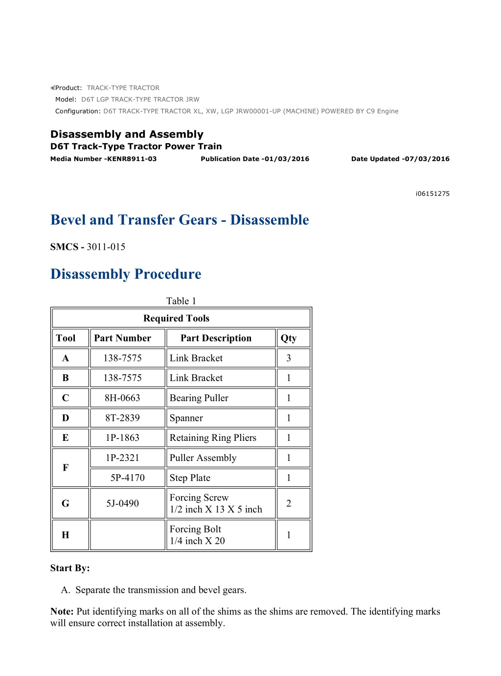
D6T TRACK-TYPE TRACTOR XL, XW, LGP JRW00001-UP (MACHINE) POWE... 1/10 Product: TRACK-TYPE TRACTOR Model: D6T LGP TRACK-TYPE TRACTOR JRW Configuration: D6T TRACK-TYPE TRACTOR XL, XW, LGP JRW00001-UP (MACHINE) POWERED BY C9 Engine Disassembly and Assembly D6T Track-Type Tractor Power Train Media Number -KENR8911-03 Publication Date -01/03/2016 Date Updated -07/03/2016 i06151275 Bevel and Transfer Gears - Disassemble SMCS - 3011-015 Disassembly Procedure Table 1 Required Tools Tool Part Number Part Description Qty A 138-7575 Link Bracket 3 B 138-7575 Link Bracket 1 C 8H-0663 Bearing Puller 1 D 8T-2839 Spanner 1 E 1P-1863 Retaining Ring Pliers 1 1P-2321 Puller Assembly 1 F 5P-4170 Step Plate 1 Forcing Screw 1/2 inch X 13 X 5 inch G 5J-0490 2 Forcing Bolt 1/4 inch X 20 H 1 Start By: A. Separate the transmission and bevel gears. Note: Put identifying marks on all of the shims as the shims are removed. The identifying marks will ensure correct installation at assembly. https://127.0.0.1/sisweb/sisweb/techdoc/techdoc_print_page.jsp?returnurl=/sis... 2021/6/24
D6T TRACK-TYPE TRACTOR XL, XW, LGP JRW00001-UP (MACHINE) POWE... 2/10 Illustration 1 g00504390 1. Remove bolts (1) and roller brackets (2) from each side of the transfer gear case. Illustration 2 g01206244 2. Remove and discard bolts (4) that hold transfer gear case (3) to the bevel gear case. 3. Install Tooling (A) and attach a suitable lifting device to Tooling (A) . Remove transfer gear case (3) from the bevel gear case. The weight of transfer gear case (3) is approximately 101 kg (223 lb). https://127.0.0.1/sisweb/sisweb/techdoc/techdoc_print_page.jsp?returnurl=/sis... 2021/6/24
D6T TRACK-TYPE TRACTOR XL, XW, LGP JRW00001-UP (MACHINE) POWE... 3/10 Illustration 3 g00839158 4. Remove bolts (5) that hold cage (6) to transfer gear case (3) . 5. Install Tooling (G) . Tighten Tooling (G) evenly. Remove the cage and the shims from the transfer gear case. Illustration 4 g00830580 6. Remove lip seal (7) and O-ring seal (8) from cage (6) . https://127.0.0.1/sisweb/sisweb/techdoc/techdoc_print_page.jsp?returnurl=/sis... 2021/6/24
https://www.ebooklibonline.com Hello dear friend! Thank you very much for reading. Enter the link into your browser. The full manual is available for immediate download. https://www.ebooklibonline.com
D6T TRACK-TYPE TRACTOR XL, XW, LGP JRW00001-UP (MACHINE) POWE... 4/10 Illustration 5 g00504397 NOTICE Bearing cup (9) and bearing (10) will be damaged if the bearing cups are removed. 7. Remove bearing cup (9) and bearing (10) from cage (6) , if necessary. Illustration 6 g00504398 8. Remove transfer gear (11) from transfer gear case (3) . Illustration 7 g00504399 NOTICE https://127.0.0.1/sisweb/sisweb/techdoc/techdoc_print_page.jsp?returnurl=/sis... 2021/6/24
D6T TRACK-TYPE TRACTOR XL, XW, LGP JRW00001-UP (MACHINE) POWE... 5/10 Bearing cones (12) will be damaged if the bearing cones are removed from transfer gear (11) . 9. Remove bearing cones (12) from transfer gear (11) , if necessary. Illustration 8 g00839162 10. Remove the bolts and install Tooling (G) in cage (13) . Tighten Tooling (G) evenly and remove cage (13) and the shims from transfer gear case (3) . 11. Remove bearing cup (14) from cage (13) . 12. Remove bearing cup (15) from transfer gear case (3) . Illustration 9 g01206569 13. Remove the bolt and the retainer from pinion gear assembly (16) . 14. Install Tooling (B) and attach a suitable lifting device. Remove pinion gear assembly (16) from the bevel gear case. The weight of pinion gear assembly (16) is approximately 33 kg (73 lb). https://127.0.0.1/sisweb/sisweb/techdoc/techdoc_print_page.jsp?returnurl=/sis... 2021/6/24
D6T TRACK-TYPE TRACTOR XL, XW, LGP JRW00001-UP (MACHINE) POWE... 6/10 15. Remove the bearing cup for the pinion gear assembly from the bevel gear case. Illustration 10 g00504402 16. Put the pinion gear assembly in a suitable press. Remove transfer gear (18) and bearing cone (17) from bevel pinion gear (20) . 17. Use Tooling (C) and a suitable press to remove bearing cone (19) from bevel pinion gear (20) . Illustration 11 g00504403 18. Bend the locking tab away from spanner nut (22) . 19. Place a pry bar between the bolt heads on the bevel gear. The prybar will prevent rotation of the bevel gear shaft. 20. Use Tooling (D) and remove spanner nut (22) . Remove lockwasher (21) and the tongue washer. https://127.0.0.1/sisweb/sisweb/techdoc/techdoc_print_page.jsp?returnurl=/sis... 2021/6/24
D6T TRACK-TYPE TRACTOR XL, XW, LGP JRW00001-UP (MACHINE) POWE... 7/10 Illustration 12 g00504404 21. Use the lifting sling and a suitable lifting device to support the bevel gear and shaft (23) in order to remove the bearings. The weight of the bevel gear and shaft (23) is approximately 55 kg (121 lb). Illustration 13 g00839205 https://127.0.0.1/sisweb/sisweb/techdoc/techdoc_print_page.jsp?returnurl=/sis... 2021/6/24
D6T TRACK-TYPE TRACTOR XL, XW, LGP JRW00001-UP (MACHINE) POWE... 8/10 Illustration 14 g00839194 22. Remove the bolts and install Tooling (G) . Tighten Tooling (G) evenly and remove cage (24) , bearing cone (26) , spacer (27) , and bearing cone (26) . Remove shims (25) from the bevel gear case. 23. Remove bearing cup (28) , center ring (29) , and bearing cup (28) from cage (24) . https://127.0.0.1/sisweb/sisweb/techdoc/techdoc_print_page.jsp?returnurl=/sis... 2021/6/24
D6T TRACK-TYPE TRACTOR XL, XW, LGP JRW00001-UP (MACHINE) POWE... 9/10 Illustration 15 g00839210 24. Remove the bolts and Tooling (G) . Tighten Tooling (G) evenly and remove cage (29A) and the bearing from the bevel gear case. 25. Use a suitable lifting device and remove bevel gear and shaft (23) from the bevel gear case. Illustration 16 g00839425 26. Install Tooling (H) and remove dowel (30) from cage (29A) . Remove race and roller assembly (31) . https://127.0.0.1/sisweb/sisweb/techdoc/techdoc_print_page.jsp?returnurl=/sis... 2021/6/24
D6T TRACK-TYPE TRACTOR XL, XW, LGP JRW00001-UP (MACHINE) POW... 10/10 Illustration 17 g00839428 27. Use Tooling (E) and remove the retaining ring from bevel gear shaft (23) . 28. Use Tooling (F) and remove bearing race (33) from the bevel gear shaft. 29. Remove bolts (32) and the nuts. Install Tooling (H) in bevel gear (34) . Tighten Tooling (H) evenly and remove the bevel gear from the bevel gear shaft. 30. Remove the tube assemblies from the bevel gear housing. https://127.0.0.1/sisweb/sisweb/techdoc/techdoc_print_page.jsp?returnurl=/sis... 2021/6/24
D6T TRACK-TYPE TRACTOR XL, XW, LGP JRW00001-UP (MACHINE) POWE... 1/16 Product: TRACK-TYPE TRACTOR Model: D6T LGP TRACK-TYPE TRACTOR JRW Configuration: D6T TRACK-TYPE TRACTOR XL, XW, LGP JRW00001-UP (MACHINE) POWERED BY C9 Engine Disassembly and Assembly D6T Track-Type Tractor Power Train Media Number -KENR8911-03 Publication Date -01/03/2016 Date Updated -07/03/2016 i03861136 Bevel and Transfer Gears - Assemble SMCS - 3011-016 Assembly Procedure Table 1 Required Tools Tool Part Number Part Description Qty A 1P-1863 Retaining Ring Pliers 1 B 8T-2839 Spanner 1 C 138-7575 Link Bracket 1 D 1P-0520 Driver Group 1 E 138-7575 Link Bracket 3 F 8T-5096 Dial Indicator 1 G 4C-8733 Tapered Gauge 1 Forcing Screw 1/2 inch X 13 X 5.00 inch H 5J-0490 2 Forcing Screw 5/8 inch X 11 X 3.50 inch J 1D-1090 1 K 1U-7234 Feeler Gauge 1 L 5P-3931 Anti-Seize Compound 1 M 7M-7260 Liquid Gasket 1 https://127.0.0.1/sisweb/sisweb/techdoc/techdoc_print_page.jsp?returnurl=/sis... 2021/6/24
D6T TRACK-TYPE TRACTOR XL, XW, LGP JRW00001-UP (MACHINE) POWE... 2/16 Illustration 1 g00504759 1. Put bevel gear (5) in position on bevel gear shaft (3). Install bolts (2) and the nuts. 2. Install Tooling (H). Use a pry bar to hold bevel gear (5) and shaft (3). Tighten bolts (2) to a torque of 475 60 N m (350 44 lb ft). 3. Raise bearing race (1) to a maximum temperature of 135 C (275 F). Install the bearing race (1) on the bevel gear shaft. 4. Use Tooling (A) and install retaining ring (4) on bevel gear shaft (3). Illustration 2 g00504761 5. Install tube assemblies (6) in the bevel gear case. 6. Use a suitable lifting device to put the bevel gear and shaft (3) in position in the bevel gear case. 7. Put bearing cone (7) in position on the bevel gear shaft. https://127.0.0.1/sisweb/sisweb/techdoc/techdoc_print_page.jsp?returnurl=/sis... 2021/6/24
D6T TRACK-TYPE TRACTOR XL, XW, LGP JRW00001-UP (MACHINE) POWE... 3/16 Illustration 3 g00504762 8. Align the dowel hole in the race and the roller assembly (9) with the hole in cage (8) and install the bearing in the cage. Install dowel (10) in the cage that holds the bearing in place. Illustration 4 g00504844 9. Position cage (8) on the bevel gear case and install bolts (11). Tighten the bolts to a torque of 135 20 N m (100 15 lb ft). Illustration 5 g00504847 10. Lower the temperature of two bearing cups (12). Install the bearing cups with center ring (13) in cage (14). https://127.0.0.1/sisweb/sisweb/techdoc/techdoc_print_page.jsp?returnurl=/sis... 2021/6/24
D6T TRACK-TYPE TRACTOR XL, XW, LGP JRW00001-UP (MACHINE) POWE... 4/16 Illustration 6 g00504848 https://127.0.0.1/sisweb/sisweb/techdoc/techdoc_print_page.jsp?returnurl=/sis... 2021/6/24
D6T TRACK-TYPE TRACTOR XL, XW, LGP JRW00001-UP (MACHINE) POWE... 5/16 Illustration 7 g00839732 11. Install cage (14) without the shims. Loosely install bolts (15) that hold cage (14) to the bevel gear case. 12. Install bearing cone (17), spacer (18A), and bearing cone (17) on the bevel gear shaft. 13. Align the notch in the bevel gear shaft with the tooth on tongue washer (16) and install tongue washer (16). 14. Align the teeth on lockwasher (17A) with the notch in the bevel gear shaft and put the lock in position. 15. Put Tooling (L) on the threads and the face of spanner nut (18). Install spanner nut (18) on the bevel gear shaft. 16. Use Tooling (B) to tighten spanner nut (18) to a torque of 612 68 N m (450 50 lb ft). Illustration 8 g00504849 17. Raise bearing cone (20) to a maximum temperature of 135 C (275 F) and install the bearing cone on bevel pinion gear (19). Use a 0.03 mm (0.001 inch) feeler gauge to make sure that the bearing cone is seated against the shoulder of the pinion gear. Illustration 9 g00504852 18. Align the splines and install transfer gear (22) on bevel pinion gear (19). https://127.0.0.1/sisweb/sisweb/techdoc/techdoc_print_page.jsp?returnurl=/sis... 2021/6/24
D6T TRACK-TYPE TRACTOR XL, XW, LGP JRW00001-UP (MACHINE) POWE... 6/16 19. Raise bearing (21) to a maximum temperature of 135 C (275 F) and install the bearing on the pinion shaft. Use a 0.03 mm (0.001 inch) feeler gauge to make sure that the bearing is seated against shoulder (23) of the pinion. Illustration 10 g01206661 20. Install Tooling (C) on the pinion and attach a suitable lifting device. Lower the pinion and pinion gear assembly (24) into position in the bevel gear case. Illustration 11 g00504854 21. Lower the temperature of bearing cup (25) and install the bearing cup in transfer gear case (26). https://127.0.0.1/sisweb/sisweb/techdoc/techdoc_print_page.jsp?returnurl=/sis... 2021/6/24
D6T TRACK-TYPE TRACTOR XL, XW, LGP JRW00001-UP (MACHINE) POWE... 7/16 Illustration 12 g00504856 22. Lower the temperature of bearing cup (28) and install the bearing cup in cage (27). Illustration 13 g00504855 23. Raise bearing cones (29) to a maximum temperature of 135 C (275 F). Install the bearing cones on lower transfer gear (30). Use a 0.03 mm (0.001 inch) feeler gauge to make sure that the bearings are seated against shoulders on the transfer gear. Illustration 14 g00504857 24. Put lower transfer gear (30) in position in transfer gear case (26). https://127.0.0.1/sisweb/sisweb/techdoc/techdoc_print_page.jsp?returnurl=/sis... 2021/6/24
D6T TRACK-TYPE TRACTOR XL, XW, LGP JRW00001-UP (MACHINE) POWE... 8/16 Illustration 15 g00504859 25. Use Tooling (D) and install bearing (33) in cage (32). 26. Lower the temperature of bearing cup (31) and install the bearing cup in cage (32). Illustration 16 g00830731 27. Put Tooling (M) in the seal bore of cage (32). Use Tooling (D) and install lip seal (34) in cage (32). Put clean oil on the lip of the seal. 28. Put glycerin on O-ring seal (35) and install the seal in the cage. Illustration 17 g00504861 29. Leave out the shims and put cage (27) in position on transfer gear case (26). Install two bolts (36). Space the bolts at 180 degrees. Do not tighten the bolts. 30. Leave out the shims and put cage (32) in position on transfer gear case (26). Install bolts (37) and (38). Space the bolts at 180 degrees. Do not tighten the bolts. https://127.0.0.1/sisweb/sisweb/techdoc/techdoc_print_page.jsp?returnurl=/sis... 2021/6/24
D6T TRACK-TYPE TRACTOR XL, XW, LGP JRW00001-UP (MACHINE) POWE... 9/16 Illustration 18 g01206662 31. Install Tooling (E) on transfer gear case (26) and attach a suitable lifting device. 32. Install the retainer and bolt (39). Tighten bolt (39) to a torque of 270 40 N m (200 30 lb ft). NOTICE Be sure that bolts (36), (37), and (38) that hold cages (27) and (32) in place on the transfer gear case are loose. 33. Put transfer gear case (26) in position on the bevel gear case. Install bolts (40) and washers. Tighten the bolts to a torque of 270 40 N m (200 30 lb ft). Illustration 19 g00843410 34. Use the following Steps to adjust the end play for the lower transfer gear: a. In order to seat the bearings, rotate the transfer gear at least three revolutions. Then, tighten bolts (37) and (38) evenly to a torque of 2.25 N m (20 lb in). b. Then, rotate the transfer gear at least three revolutions. Tighten bolts (37) and (38) evenly to a torque of 4.5 N m (40 lb in). https://127.0.0.1/sisweb/sisweb/techdoc/techdoc_print_page.jsp?returnurl=/sis... 2021/6/24
D6T TRACK-TYPE TRACTOR XL, XW, LGP JRW00001-UP (MACHINE) POW... 10/16 c. Use Tooling (K) to measure the gap between cage (32) and the transfer gear case. Make the measurement at the edge of the cage in line with the center of bolts (37) and (38). Average the two measurements. d. Add 0.23 mm (0.009 inch) to the average figure that was obtained in Step 34.c. This figure will be the correct thickness for the shims that should be used. 35. Remove cage (32). Put the correct thickness of shims in position on the transfer gear case. Put cage (32) in position and install the bolts that hold the cage in place. Tighten the bolts to a torque of 135 20 N m (100 15 lb ft). The bearing end play will be 0.10 0.05 mm (0.004 0.002 inch). It will not be necessary to check the bearing end play if this procedure for adjustment has been followed. If a measurement of the bearing end play is desired, refer to Measurement of the Bearing End Play for the Bevel Pinion and Transfer Gears in this section. 36. Put two roller bracket (41) in position and install the bolts that hold each one. Tighten the bolts to a torque of 270 40 N m (200 30 lb ft). Illustration 20 g00843412 37. Use the following Steps to adjust the end play for the upper transfer and pinion gear: a. In order to seat the bearings, rotate the transfer gear at least three revolutions. Then, tighten bolts (36) evenly to a torque of 4.5 N m (40 lb in). b. Then, rotate the transfer gear at least three revolutions. Tighten bolts (36) evenly to a torque of 9.0 N m (80 lb in). c. Use Tooling (K) to measure the gap between cage (27) and the transfer gear case. Make the measurement at the edge of the cage in line with the center of bolts (36). Average the two measurements. d. Add 0.43 mm (0.017 inch) to the average figure that was obtained in Step 37.c. This figure will be the correct thickness for the shims that should be used. 38. Remove cage (27). Put the correct thickness of shims in position on the transfer gear case. Put cage (27) in position and install the bolts that hold the cage in place. Tighten the bolts to a torque of 135 20 N m (100 15 lb ft). The bearing end play will be 0.10 0.05 mm (0.004 0.002 inch). It will not be necessary to check the bearing end play if this procedure for adjustment has been followed. If a measurement of the bearing end play is desired, refer https://127.0.0.1/sisweb/sisweb/techdoc/techdoc_print_page.jsp?returnurl=/sis... 2021/6/24
D6T TRACK-TYPE TRACTOR XL, XW, LGP JRW00001-UP (MACHINE) POW... 11/16 to Measurement of the Bearing End Play for the Bevel Pinion and Transfer Gears in this section. Illustration 21 g00504885 Illustration 22 g00839501 39. Put the bevel gear case on the side so that the bevel gear shaft is in a vertical position with the bevel gear at the bottom. NOTICE It is important for the bevel gear case to be in this position. The bevel gear must be held as far away from the pinion gear as possible when the gear clearance (backlash) is set. 40. Install Tooling (J) in the transfer gear case. Tighten Tooling (J) until there is no movement in the pinion gear. Be sure that Tooling (J) is between the teeth of the gear. 41. Put Tooling (F) in position and check the clearance (backlash) between the bevel gear and the pinion gear. The clearance (backlash) must be 0.30 + 0.12 mm 0.10 mm (0.012 + 0.005 inch 0.004 inch). Check the clearance (backlash) on three different teeth that are evenly spaced around the gear. https://127.0.0.1/sisweb/sisweb/techdoc/techdoc_print_page.jsp?returnurl=/sis... 2021/6/24
D6T TRACK-TYPE TRACTOR XL, XW, LGP JRW00001-UP (MACHINE) POW... 12/16 42. The difference between the high measurement and the low measurement must not be more than 0.15 mm (0.006 inch). 43. Install the correct amount of shims (42) under bearing cage (14). Install the six bolts in the cage and tighten the bolts to a torque of 135 20 N m (100 15 lb ft). 44. Check the gear clearance (backlash) in order to be certain that the clearance is still correct. If the clearance is not correct, add or remove shims (42), as needed. NOTICE Tooling (J) must be removed. 45. Remove Tooling (J) from the transfer gear case. End By: a. Connect the transmission and the bevel gears. Measurement of the Bearing End Play for the Bevel Pinion and Transfer Gears Table 2 Tooling Setup Item Part Number Part Description Qty L 5P-8247 Hardened Washer 4 M 4B-5275 Washer 4 N 1D-4720 Nut 4 P 1P-1837 Bearing Puller Adapter 2 Rod 5/8 -11 NC 24 R 1 S 2P-8257 Modified Plate 1 T 2P-8260 Installer (liner) 1 U 1D-4720 Nut 5 V 8T-5096 Dial Indicator 1 W 0L-1143 Bolt 1 Y 5M-2894 Washer 4 https://127.0.0.1/sisweb/sisweb/techdoc/techdoc_print_page.jsp?returnurl=/sis... 2021/6/24
D6T TRACK-TYPE TRACTOR XL, XW, LGP JRW00001-UP (MACHINE) POW... 13/16 The bearing end play for the bevel pinion and transfer gears should be adjusted according to the procedure that is given in Bevel and Transfer Gears - Assemble . If this procedure is used, the bearing end play (backlash) should be correctly set at 0.10 0.05 mm (0.004 0.002 inch). NOTICE It is very important to load the bearings vertically in both the upward direction and the downward direction when you make the measurements. Otherwise, false readings will result. If a check of bearing end play is desired, the measurement must be made only while the bearings are being rotated and loaded with the Tooling that is shown. Illustration 23 g00843736 Illustration 24 g00843737 https://127.0.0.1/sisweb/sisweb/techdoc/techdoc_print_page.jsp?returnurl=/sis... 2021/6/24
D6T TRACK-TYPE TRACTOR XL, XW, LGP JRW00001-UP (MACHINE) POW... 14/16 Illustration 25 g00843739 Illustration 26 g00843740 Tooling (S) requires an additional hole that is 16.00 mm (0.630 inch) (5/8 inch) in diameter. Tooling (s) is also a part of Tooling (T). Drill the hole for Tooling (W) 25 mm (1.0 inch) from the tapped center hole, as shown. This is the Tooling that will be used to check the bearing clearance for the input transfer gear. The transfer gear is clamped to Tooling (P). Tooling (T) is used to force the gear to move. The gear can be moved upward or the gear can be moved downward with the lever. Tooling (L) fits in Tooling (P) to center Tooling (R) in the gear. Note: Use the following Steps to measure the bearing clearance for the input transfer gear. 1. Install the Tooling in the transfer gear so that Tooling (R) and Tooling (P) are centered in the gear. Install Tooling (R) with the 5/8 by 11 thread on top. 2. Tighten Tooling (U) on top of the adapter in order to prevent movement of the gear. Tooling (N) can then be used to turn the gear. 3. Fasten Tooling (S) and Tooling (T) to the housing with Tooling (W), as shown. Use Tooling (Y) to support the plate. 4. Put the slotted end of the lever in a horizontal position on the threaded rod. Be sure that there is 1.0 mm (0.04 inch) clearance between Tooling (M) and the lever. 5. Lubricate the washers so that the assembly will turn smoothly. https://127.0.0.1/sisweb/sisweb/techdoc/techdoc_print_page.jsp?returnurl=/sis... 2021/6/24
D6T TRACK-TYPE TRACTOR XL, XW, LGP JRW00001-UP (MACHINE) POW... 15/16 6. Put Tooling (V) in position. Be sure that the indicator tip is vertical and that the indicator tip is in contact with the top adapter. Lubricate the surface of the adapter or lubricate the indicator tip. 7. Push the adapter downward and hold the adapter down while the lever is up. Use a ratchet wrench to turn the gear with Tooling (N). Rotate the gear for at least three revolutions. Watch the needle on the dial indicator. Watch the backward movement and the forward movement. Stop rotating the gear at the point of the maximum needle movement. Note: The needle may move back and forth during rotation due to runout in the adapter. The reading should always be taken at the same location so that the measurement will be accurate and consistent. 8. Mark the location of Area (X). Mark the location at the point of maximum needle movement on the surface of the adapter. Set the dial indicator to zero as you force the gear downward. 9. Pull the gear upward by pulling the lever downward. Do this procedure as you turn the gear at least three revolutions. Record the maximum reading that is obtained when the indicator tip is returned to Area (X). This reading will be the actual bearing clearance. The reading should be 0.10 0.05 mm (0.004 0.002 inch). 10. Repeat the procedure. The result should be identical if the first procedure was correctly done. Note: Use the following Steps to measure the bearing clearance for the pinion gear. 11. Screw the 5/8 - 11 NC end of Tooling (R) in the pinion shaft. 12. Put the lever assembly and Tooling (S) in position. Install Tooling (W) in the bearing retainer. Use Tooling (Y) to support the plate. 13. Adjust Tooling (U) so that the slotted end of the lever is horizontal. 14. Allow 1.0 mm (0.04 inch) clearance between the lever and Tooling (M). Lubricate both washers. 15. Put Tooling (V) in position, as shown. Be sure that the indicator tip is vertical and that the indicator tip is in contact with the flat end surface of the pinion gear. Lubricate the flat end surface of the pinion gear or lubricate the indicator tip. 16. Rotate the pinion for at least three revolutions as you force the pinion gear downward by lifting up on Tooling (T). Watch the backward movement and the forward movement of the needle on the dial indicator as the pinion gear is being rotated. Stop rotating the pinion gear at the point of the maximum needle movement. Mark the location at the point of maximum needle movement on the surface of the pinion gear. Set the dial indicator to zero as you force the pinion gear downward. Note: The needle may move back and forth during rotation due to runout in the surface of the pinion gear. The reading should always be taken at the same location so that the measurement will be accurate and consistent. 17. Pull the pinion gear upward by pulling the lever downward. Do this procedure as you turn the pinion gear at least three revolutions. Record the maximum reading that is obtained https://127.0.0.1/sisweb/sisweb/techdoc/techdoc_print_page.jsp?returnurl=/sis... 2021/6/24
D6T TRACK-TYPE TRACTOR XL, XW, LGP JRW00001-UP (MACHINE) POW... 16/16 when the indicator tip is returned to the marked location. This reading will be the actual bearing clearance. The reading should be 0.10 0.05 mm (0.004 0.002 inch). 18. Repeat the procedure. The result should be identical if the first procedure was correctly done. https://127.0.0.1/sisweb/sisweb/techdoc/techdoc_print_page.jsp?returnurl=/sis... 2021/6/24
D6T TRACK-TYPE TRACTOR XL, XW, LGP JRW00001-UP (MACHINE) POWE... 1/5 Product: TRACK-TYPE TRACTOR Model: D6T LGP TRACK-TYPE TRACTOR JRW Configuration: D6T TRACK-TYPE TRACTOR XL, XW, LGP JRW00001-UP (MACHINE) POWERED BY C9 Engine Disassembly and Assembly D6T Track-Type Tractor Power Train Media Number -KENR8911-03 Publication Date -01/03/2016 Date Updated -07/03/2016 i04295689 Transmission - Remove and Install SMCS - 3030-010 Removal Procedure Table 1 Required Tools Tool Part Number Part Description Qty 369-6017 Transmission Case Cover 1 A 142-6893 Adjustable Hook 1 Start By: A. Remove the ROPS. B. Remove the drive shaft. 1. If equipped, lower the ripper to the ground. Remove the ripper shanks or invert the ripper shanks. 2. Drain the power train oil into a suitable container for storage or disposal. Refer to Operation and Maintenance Manual , "Transmission Oil - Change". https://127.0.0.1/sisweb/sisweb/techdoc/techdoc_print_page.jsp?returnurl=/sis... 2021/6/24
D6T TRACK-TYPE TRACTOR XL, XW, LGP JRW00001-UP (MACHINE) POWE... 2/5 Illustration 1 g02350749 Illustration 2 g02350755 3. Remove bolts (1) and bolts (2) . Use two people in order to remove guard assembly (3) . The weight of guard assembly (3) is approximately 27 kg (60 lb). Note: Do not disconnect the ripper lines. Illustration 3 g02350760 https://127.0.0.1/sisweb/sisweb/techdoc/techdoc_print_page.jsp?returnurl=/sis... 2021/6/24
Suggest: If the above button click is invalid. Please download this document first, and then click the above link to download the complete manual. Thank you so much for reading
D6T TRACK-TYPE TRACTOR XL, XW, LGP JRW00001-UP (MACHINE) POWE... 3/5 4. Remove guard assembly (4) . Illustration 4 g02350764 5. Disconnect harness assembly (5) and bracket (6) . Illustration 5 g02350770 6. Disconnect hose assemblies (7) . https://127.0.0.1/sisweb/sisweb/techdoc/techdoc_print_page.jsp?returnurl=/sis... 2021/6/24
https://www.ebooklibonline.com Hello dear friend! Thank you very much for reading. Enter the link into your browser. The full manual is available for immediate download. https://www.ebooklibonline.com
")
")
")

")
")
")
")
")
")
")
")
")
")
")
")
")
")
")
")
")
")
")
")
")
")
")
")
")

")