Caterpillar Cat D6K2 LGP TRACK-TYPE TRACTOR (Prefix RST) Service Repair Manual Instant Download
Please open the website below to get the complete manualnn//

Download Presentation

Please find below an Image/Link to download the presentation.
The content on the website is provided AS IS for your information and personal use only. It may not be sold, licensed, or shared on other websites without obtaining consent from the author. Download presentation by click this link. If you encounter any issues during the download, it is possible that the publisher has removed the file from their server.
E N D
Presentation Transcript
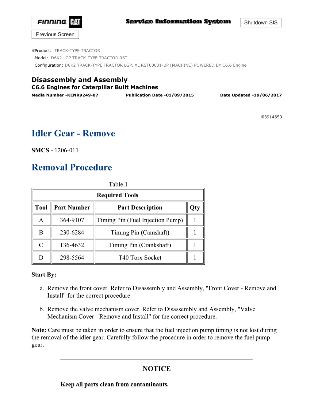
D6K2 TRACK-TYPE TRACTOR LGP, XL RST00001-UP (MACHINE) POWERED ... 1/6 Shutdown SIS Previous Screen Product: TRACK-TYPE TRACTOR Model: D6K2 LGP TRACK-TYPE TRACTOR RST Configuration: D6K2 TRACK-TYPE TRACTOR LGP, XL RST00001-UP (MACHINE) POWERED BY C6.6 Engine Disassembly and Assembly C6.6 Engines for Caterpillar Built Machines Media Number -KENR9249-07 Publication Date -01/09/2015 Date Updated -19/06/2017 i03914650 Idler Gear - Remove SMCS - 1206-011 Removal Procedure Table 1 Required Tools Tool Part Number Part Description Qty A 364-9107 Timing Pin (Fuel Injection Pump) 1 B 230-6284 Timing Pin (Camshaft) 1 C 136-4632 Timing Pin (Crankshaft) 1 D 298-5564 T40 Torx Socket 1 Start By: a. Remove the front cover. Refer to Disassembly and Assembly, "Front Cover - Remove and Install" for the correct procedure. b. Remove the valve mechanism cover. Refer to Disassembly and Assembly, "Valve Mechanism Cover - Remove and Install" for the correct procedure. Note: Care must be taken in order to ensure that the fuel injection pump timing is not lost during the removal of the idler gear. Carefully follow the procedure in order to remove the fuel pump gear. NOTICE Keep all parts clean from contaminants. https://127.0.0.1/sisweb/sisweb/techdoc/techdoc_print_page.jsp?returnurl=/sis... 2021/12/21
D6K2 TRACK-TYPE TRACTOR LGP, XL RST00001-UP (MACHINE) POWERED ... 2/6 Contaminants may cause rapid wear and shorten component life. Illustration 1 g01994555 https://127.0.0.1/sisweb/sisweb/techdoc/techdoc_print_page.jsp?returnurl=/sis... 2021/12/21
D6K2 TRACK-TYPE TRACTOR LGP, XL RST00001-UP (MACHINE) POWERED ... 3/6 Illustration 2 g01994553 1. Rotate the crankshaft so that number one piston is at top dead center on the compression stroke. Refer to System Operation, Testing and Adjusting, "Finding Top Center Position for No.1 Piston" for the correct procedure. 2. Remove plug (2) from the cylinder block and remove O-ring seal (1) from the plug. 3. Ensure that Tooling (C) is installed in Hole (Y) in the cylinder block. Use Tooling (C) in order to lock the crankshaft in the correct position. 4. Ensure that Tooling (B) is installed into Hole (X) in camshaft gear (3). Use Tooling (B) in order to lock the camshaft in the correct position. Note: Ensure that the gears are marked in order to show alignment. Refer to Illustration 2. 5. Use Tooling (A) in order to lock the fuel injection pump gear in the correct position. Refer to Disassembly and Assembly, "Fuel Injection Pump - Remove" for the correct procedure. https://127.0.0.1/sisweb/sisweb/techdoc/techdoc_print_page.jsp?returnurl=/sis... 2021/12/21
https://www.ebooklibonline.com Hello dear friend! Thank you very much for reading. Enter the link into your browser. The full manual is available for immediate download. https://www.ebooklibonline.com
D6K2 TRACK-TYPE TRACTOR LGP, XL RST00001-UP (MACHINE) POWERED ... 4/6 Illustration 3 g01994556 6. Use Tooling (D) in order to loosen threaded inserts (5) on all rocker arms (6). Unscrew threaded inserts (5) on all rocker arms (6) until all valves are fully closed. Note: Failure to ensure that ALL threaded inserts are fully unscrewed can result in contact between the valves and pistons. https://127.0.0.1/sisweb/sisweb/techdoc/techdoc_print_page.jsp?returnurl=/sis... 2021/12/21
D6K2 TRACK-TYPE TRACTOR LGP, XL RST00001-UP (MACHINE) POWERED ... 5/6 Illustration 4 g01994576 https://127.0.0.1/sisweb/sisweb/techdoc/techdoc_print_page.jsp?returnurl=/sis... 2021/12/21
D6K2 TRACK-TYPE TRACTOR LGP, XL RST00001-UP (MACHINE) POWERED ... 6/6 Illustration 5 g01994557 7. Mark plate (8) in order to show orientation. Note: Identification will ensure that the plate can be installed in the original orientation. 8. Remove bolts (7). 9. Remove plate (8). 10. Remove the assembly of idler gear (4). 11. Remove hub (9) from the recess in the front housing. Copyright 1993 - 2021 Caterpillar Inc. Tue Dec 21 16:48:42 UTC+0800 2021 All Rights Reserved. Private Network For SIS Licensees. https://127.0.0.1/sisweb/sisweb/techdoc/techdoc_print_page.jsp?returnurl=/sis... 2021/12/21
D6K2 TRACK-TYPE TRACTOR LGP, XL RST00001-UP (MACHINE) POWERED ... 1/8 Shutdown SIS Previous Screen Product: TRACK-TYPE TRACTOR Model: D6K2 LGP TRACK-TYPE TRACTOR RST Configuration: D6K2 TRACK-TYPE TRACTOR LGP, XL RST00001-UP (MACHINE) POWERED BY C6.6 Engine Disassembly and Assembly C6.6 Engines for Caterpillar Built Machines Media Number -KENR9249-07 Publication Date -01/09/2015 Date Updated -19/06/2017 i03914656 Idler Gear - Install SMCS - 1206-012 Installation Procedure Table 1 Required Tools Tool Part Number Part Description Qty A 364-9107 Timing Pin (Fuel Injection Pump) 1 B 230-6284 Timing Pin (Camshaft) 1 C 136-4632 Timing Pin (Crankshaft) 1 D 298-5564 T40 Torx Socket 1 9U-7324 Indicator Bracket 1 7H-1942 Dial Indicator 1 E 3S-3268 Indicator Contact Point 1 7H-1940 Universal Attachment 1 NOTICE Keep all parts clean from contaminants. Contaminants may cause rapid wear and shorten component life. https://127.0.0.1/sisweb/sisweb/techdoc/techdoc_print_page.jsp?returnurl=/sis... 2021/12/21
D6K2 TRACK-TYPE TRACTOR LGP, XL RST00001-UP (MACHINE) POWERED ... 2/8 Illustration 1 g01996476 https://127.0.0.1/sisweb/sisweb/techdoc/techdoc_print_page.jsp?returnurl=/sis... 2021/12/21
D6K2 TRACK-TYPE TRACTOR LGP, XL RST00001-UP (MACHINE) POWERED ... 3/8 Illustration 2 g01996475 1. Ensure that Tooling (C) is installed in Hole (Y) in the cylinder block. Use Tooling (C) in order to lock the crankshaft in the correct Position. Refer to System Operation, Testing and Adjusting, "Finding Top Center Position for No.1 Piston" for the correct procedure. 2. Ensure that Tooling (B) is installed into Hole (X) in camshaft gear (3). 3. Use Tooling (A) in order to lock the fuel injection pump gear in the correct position. Refer to Disassembly and Assembly, "Fuel Injection Pump - Remove" for the correct procedure. https://127.0.0.1/sisweb/sisweb/techdoc/techdoc_print_page.jsp?returnurl=/sis... 2021/12/21
D6K2 TRACK-TYPE TRACTOR LGP, XL RST00001-UP (MACHINE) POWERED ... 4/8 Illustration 3 g01996477 https://127.0.0.1/sisweb/sisweb/techdoc/techdoc_print_page.jsp?returnurl=/sis... 2021/12/21
D6K2 TRACK-TYPE TRACTOR LGP, XL RST00001-UP (MACHINE) POWERED ... 5/8 Illustration 4 g02196594 https://127.0.0.1/sisweb/sisweb/techdoc/techdoc_print_page.jsp?returnurl=/sis... 2021/12/21
D6K2 TRACK-TYPE TRACTOR LGP, XL RST00001-UP (MACHINE) POWERED ... 6/8 Illustration 5 g01996576 4. Clean idler gear (4) and inspect the idler gear for wear and damage. Refer to Specifications, "Gear Group (Front)" for more information. If necessary, replace the idler gear. 5. Clean hub (9) and inspect the hub for wear and damage. Refer to Specifications, "Gear Group (Front)" for more information. If necessary, replace the hub. 6. Lubricate hub (9) with clean engine oil. Install hub (9) into the recess in the front housing. Ensure that oil Hole (Z) is position as shown in the Illustration 4. 7. Install idler gear (4) onto hub (9). Ensure that the timing marks are toward the front of the idler gear. 8. Align the timing mark on idler gear (4) with the timing mark on camshaft gear (3), fuel injection pump gear (10) and crankshaft gear (11). Refer to the Illustration 5. Install the assembly of idler gear (4) to hub (9). 9. Clean plate (8) and inspect the plate for wear and damage. If necessary, replace the plate. 10. Lubricate plate (8) with clean engine oil. Align the holes in plate (8) with the holes in hub (9). Install the plate in the original orientation. Note: Ensure that the identification mark TOP is upward. 11. Install bolts (7). Tighten the bolts to a torque of 44 N m (32 lb ft). 12. Remove Tooling (A), Tooling (B), and Tooling (C). https://127.0.0.1/sisweb/sisweb/techdoc/techdoc_print_page.jsp?returnurl=/sis... 2021/12/21
D6K2 TRACK-TYPE TRACTOR LGP, XL RST00001-UP (MACHINE) POWERED ... 7/8 Note: Ensure that timing marks are aligned, before removing the Tooling (A), Tooling (B) and Tooling (C). Illustration 6 g01996554 13. Position a new O-ring seal (1) onto plug (2). Install the plug to the cylinder block and tighten the plug to a torque of 21 N m (186 lb in). 14. Use Tooling (E) in order to check the end play for the idler gear. Refer to Specifications, "Gear Group (Front)" for more information. 15. Use Tooling (E) in order to check the backlash between the idler gear and the camshaft gear. Refer to Specifications, "Gear Group (Front)" for more information. 16. Use Tooling (E) in order to check the backlash between the idler gear and the crankshaft gear. Refer to Specifications, "Gear Group (Front)" for more information. 17. Use Tooling (E) in order to check the backlash between the idler gear and the fuel injection pump gear. Refer to Specifications, "Gear Group (Front)" for more information. 18. Lightly lubricate all of the gears with clean engine oil. https://127.0.0.1/sisweb/sisweb/techdoc/techdoc_print_page.jsp?returnurl=/sis... 2021/12/21
D6K2 TRACK-TYPE TRACTOR LGP, XL RST00001-UP (MACHINE) POWERED ... 8/8 Illustration 7 g01994556 19. Rotate the crankshaft in a clockwise direction and position the crankshaft at 60 degrees after top dead center. Refer to System Operation, Testing and Adjusting, "Position the Valve Mechanism Before Maintenance Procedures" for the correct procedure. 20. Use Tooling (D) in order to tighten threaded inserts (4) on all rocker arms (5). Tighten the threaded inserts to a torque of 30 N m (266 lb in). Note: When the threaded insert is tightened, the threaded insert must be seated correctly into the cup for the pushrod. 21. The engine should not be operated for a period 30 minutes after the threaded inserts on all the rocker arms have been tightened. This period will allow the force from the valve springs to purge off excessive engine oil from the hydraulic lifters. End By: a. Install the front cover. Refer to Disassembly and Assembly, "Front Cover - Remove and Install" for the correct procedure. b. Install the valve mechanism cover. Refer to Disassembly and Assembly, "Valve Mechanism Cover - Remove and Install" for the correct procedure. Copyright 1993 - 2021 Caterpillar Inc. Tue Dec 21 16:49:38 UTC+0800 2021 All Rights Reserved. Private Network For SIS Licensees. https://127.0.0.1/sisweb/sisweb/techdoc/techdoc_print_page.jsp?returnurl=/sis... 2021/12/21
D6K2 TRACK-TYPE TRACTOR LGP, XL RST00001-UP (MACHINE) POWERED ... 1/4 Shutdown SIS Previous Screen Product: TRACK-TYPE TRACTOR Model: D6K2 LGP TRACK-TYPE TRACTOR RST Configuration: D6K2 TRACK-TYPE TRACTOR LGP, XL RST00001-UP (MACHINE) POWERED BY C6.6 Engine Disassembly and Assembly C6.6 Engines for Caterpillar Built Machines Media Number -KENR9249-07 Publication Date -01/09/2015 Date Updated -19/06/2017 i03914670 Housing (Front) - Remove SMCS - 1151-011 Removal Procedure Start By: a. Remove the fan. Refer to Disassembly and Assembly, "Fan - Remove and Install" for the correct procedure. b. Remove the crankshaft pulley. Refer to Disassembly and Assembly, "Vibration Damper and Pulley - Remove" for the correct procedure. c. Remove the engine oil pan plate. Refer to Disassembly and Assembly, "Engine Oil Pan Plate - Remove" for the correct procedure. d. If the engine has an accessory drive, remove the accessory drive. Refer to Disassembly and Assembly, "Accessory Drive - Remove and Install" for the correct procedure. e. Remove the water pump. Refer to Disassembly and Assembly, "Water Pump - Remove" for the correct procedure. f. Remove the timing gears. Refer to Disassembly and Assembly, "Gear Group (Front) - Remove and Install" for the correct procedure. g. Remove the fuel injection pump. Refer to Disassembly and Assembly, "Fuel Injection Pump - Remove" for the correct procedure. NOTICE Keep all parts clean from contaminants. Contaminants may cause rapid wear and shorten component life. https://127.0.0.1/sisweb/sisweb/techdoc/techdoc_print_page.jsp?returnurl=/sis... 2021/12/21
D6K2 TRACK-TYPE TRACTOR LGP, XL RST00001-UP (MACHINE) POWERED ... 2/4 NOTICE Care must be taken to ensure that fluids are contained during performance of inspection, maintenance, testing, adjusting and repair of the product. Be prepared to collect the fluid with suitable containers before opening any compartment or disassembling any component containing fluids. Dispose of all fluids according to local regulations and mandates. Illustration 1 g02198874 1. Cut cable strap (2) from wiring harness assembly. 2. Remove bolts (3) that secure bypass tube (1) to front housing (4). 3. Remove bypass tube (1) from the cylinder head. Remove O-ring (5) and O-ring (6) from bypass tube (1). https://127.0.0.1/sisweb/sisweb/techdoc/techdoc_print_page.jsp?returnurl=/sis... 2021/12/21
D6K2 TRACK-TYPE TRACTOR LGP, XL RST00001-UP (MACHINE) POWERED ... 3/4 Illustration 2 g02198875 4. Remove bolts (7), bolts (8) and bolts (9) from front housing (4). Note: The bolts are three different lengths. Note the positions of the different bolts. 5. Remove front housing (4) from the cylinder block. 6. Remove gasket (10). https://127.0.0.1/sisweb/sisweb/techdoc/techdoc_print_page.jsp?returnurl=/sis... 2021/12/21
D6K2 TRACK-TYPE TRACTOR LGP, XL RST00001-UP (MACHINE) POWERED ... 4/4 Illustration 3 g02198876 7. Remove thrust washer (11) from the cylinder block. Copyright 1993 - 2021 Caterpillar Inc. Tue Dec 21 16:50:33 UTC+0800 2021 All Rights Reserved. Private Network For SIS Licensees. https://127.0.0.1/sisweb/sisweb/techdoc/techdoc_print_page.jsp?returnurl=/sis... 2021/12/21
D6K2 TRACK-TYPE TRACTOR LGP, XL RST00001-UP (MACHINE) POWERED ... 1/4 Shutdown SIS Previous Screen Product: TRACK-TYPE TRACTOR Model: D6K2 LGP TRACK-TYPE TRACTOR RST Configuration: D6K2 TRACK-TYPE TRACTOR LGP, XL RST00001-UP (MACHINE) POWERED BY C6.6 Engine Disassembly and Assembly C6.6 Engines for Caterpillar Built Machines Media Number -KENR9249-07 Publication Date -01/09/2015 Date Updated -19/06/2017 i03914677 Housing (Front) - Remove - Heavy Duty Housing (Front) SMCS - 1151-011 Removal Procedure Start By: a. Remove the fan. Refer to Disassembly and Assembly, "Fan - Remove and Install" for the correct procedure. b. Remove the crankshaft pulley. Refer to Disassembly and Assembly, "Vibration Damper and Pulley - Remove" for the correct procedure. c. Remove the engine oil pan plate. Refer to Disassembly and Assembly, "Engine Oil Pan Plate - Remove" for the correct procedure. d. If the engine has an accessory drive, remove the accessory drive. Refer to Disassembly and Assembly, "Accessory Drive - Remove and Install" for the correct procedure. e. Remove the water pump. Refer to Disassembly and Assembly, "Water Pump - Remove" for the correct procedure. f. Remove the timing gears. Refer to Disassembly and Assembly, "Gear Group (Front) - Remove and Install" for the correct procedure. g. Remove the fuel injection pump. Refer to Disassembly and Assembly, "Fuel Injection Pump - Remove" for the correct procedure. NOTICE Keep all parts clean from contaminants. Contaminants may cause rapid wear and shorten component life. https://127.0.0.1/sisweb/sisweb/techdoc/techdoc_print_page.jsp?returnurl=/sis... 2021/12/21
D6K2 TRACK-TYPE TRACTOR LGP, XL RST00001-UP (MACHINE) POWERED ... 2/4 NOTICE Care must be taken to ensure that fluids are contained during performance of inspection, maintenance, testing, adjusting and repair of the product. Be prepared to collect the fluid with suitable containers before opening any compartment or disassembling any component containing fluids. Dispose of all fluids according to local regulations and mandates. Illustration 1 g02198874 1. Cut cable strap (2) from wiring harness assembly. 2. Remove bolts (3) that secure bypass tube (1) to front housing (4). 3. Remove bypass tube (1) from the cylinder head. Remove O-ring (5) and O-ring (6) from bypass tube (1). https://127.0.0.1/sisweb/sisweb/techdoc/techdoc_print_page.jsp?returnurl=/sis... 2021/12/21
D6K2 TRACK-TYPE TRACTOR LGP, XL RST00001-UP (MACHINE) POWERED ... 3/4 Illustration 2 g02201095 4. Remove bolts (8), bolts (9) and bolts (10) from front housing (4). Note: The bolts are three different lengths. Note the positions of the different length bolts. 5. Remove front housing (4) from the cylinder block. 6. Remove gasket (11). 7. If necessary, follow Step 7.a through Step 7.b in order to remove bearing (7) from housing (3). a. Place housing (4) onto a suitable support. b. Use a suitable tool in order to press bearing (7) out of housing (4). https://127.0.0.1/sisweb/sisweb/techdoc/techdoc_print_page.jsp?returnurl=/sis... 2021/12/21
D6K2 TRACK-TYPE TRACTOR LGP, XL RST00001-UP (MACHINE) POWERED ... 4/4 Illustration 3 g02201096 8. Remove thrust washer (12) from the cylinder block. Copyright 1993 - 2021 Caterpillar Inc. Tue Dec 21 16:51:29 UTC+0800 2021 All Rights Reserved. Private Network For SIS Licensees. https://127.0.0.1/sisweb/sisweb/techdoc/techdoc_print_page.jsp?returnurl=/sis... 2021/12/21
D6K2 TRACK-TYPE TRACTOR LGP, XL RST00001-UP (MACHINE) POWERED ... 1/8 Shutdown SIS Previous Screen Product: TRACK-TYPE TRACTOR Model: D6K2 LGP TRACK-TYPE TRACTOR RST Configuration: D6K2 TRACK-TYPE TRACTOR LGP, XL RST00001-UP (MACHINE) POWERED BY C6.6 Engine Disassembly and Assembly C6.6 Engines for Caterpillar Built Machines Media Number -KENR9249-07 Publication Date -01/09/2015 Date Updated -19/06/2017 i05215624 Housing (Front) - Install - Heavy Duty Housing (Front) SMCS - 1151-012 Installation Procedure Table 1 Required Tools Tool Part Number Part Description Qty A 6V-6640 Sealant 1 Guide Bolt M8 by 40 mm B - 2 319-6486 Alignment Tool 1 C Bolts - 3 M10 by 50 mm D 1U-6396 O-Ring Assembly Compound 1 E 7M-7456 Bearing Mount Compound 1 NOTICE Keep all parts clean from contaminants. Contaminants may cause rapid wear and shortened component life. 1. Ensure that the front housing is clean and free from damage. If necessary, replace the front housing. https://127.0.0.1/sisweb/sisweb/techdoc/techdoc_print_page.jsp?returnurl=/sis... 2021/12/21
D6K2 TRACK-TYPE TRACTOR LGP, XL RST00001-UP (MACHINE) POWERED ... 2/8 If necessary, install blanking plugs to a new front housing. Use Tooling (A) in order to seal all D-plugs. 2. Clean all the gasket surfaces of the cylinder block. Illustration 1 g02201113 https://127.0.0.1/sisweb/sisweb/techdoc/techdoc_print_page.jsp?returnurl=/sis... 2021/12/21
D6K2 TRACK-TYPE TRACTOR LGP, XL RST00001-UP (MACHINE) POWERED ... 3/8 Illustration 2 g02201114 3. Inspect dowel (13) and dowel (14) for damage. If necessary, replace the dowels in the cylinder block. 4. Install thrust washer (12) into the recess in the cylinder block. Refer to Disassembly and Assembly, "Camshaft - Install" for more information. 5. Install Tooling (B) to the cylinder block. Refer to Illustration 2. 6. Align a new gasket (11) with Tooling (B) . Install the gasket to the cylinder block. Note: Ensure that two circular Tabs (X) on the gasket are engaged in two Holes (Y) in the cylinder block. Ensure that dowel (14) in the cylinder block is engaged on the gasket. 7. Install Tooling (C) to the cylinder block. https://127.0.0.1/sisweb/sisweb/techdoc/techdoc_print_page.jsp?returnurl=/sis... 2021/12/21
D6K2 TRACK-TYPE TRACTOR LGP, XL RST00001-UP (MACHINE) POWERED ... 4/8 Illustration 3 g02201115 8. If necessary, follow Step 8.a through Step 8.c in order to install bearing (7) to housing (4) . a. Apply a small continuous bead of Tooling (E) to outer Surface (Z) of bearing (7) . b. Place housing (4) onto a suitable support. c. Use a suitable tool in order to press bearing (7) into housing (3) until the bearing is in the correct position within the housing. Remove any excess bearing mount compound. 9. Install the front housing over Tooling (B) and Tooling (C) onto the cylinder block. https://127.0.0.1/sisweb/sisweb/techdoc/techdoc_print_page.jsp?returnurl=/sis... 2021/12/21
Suggest: If the above button click is invalid. Please download this document first, and then click the above link to download the complete manual. Thank you so much for reading
D6K2 TRACK-TYPE TRACTOR LGP, XL RST00001-UP (MACHINE) POWERED ... 5/8 Illustration 4 g02201116 (8) M8 by 20 mm (9) M8 by 35 mm (10) M8 by 25 mm 10. Install new bolts (10) to front housing (3) hand tight. 11. Remove Tooling (B) . 12. Loosely install bolts (8) and bolts (9) finger tight. Refer to Illustration 4 for the correct position of the bolts. https://127.0.0.1/sisweb/sisweb/techdoc/techdoc_print_page.jsp?returnurl=/sis... 2021/12/21
D6K2 TRACK-TYPE TRACTOR LGP, XL RST00001-UP (MACHINE) POWERED ... 6/8 Illustration 5 g02058297 13. Tighten bolts (8) , bolts (9) and bolts (10) in the sequence that is shown in Illustration 5 to a torque of 28 N m (248 lb in). 14. Remove Tooling (C) from the cylinder block. https://127.0.0.1/sisweb/sisweb/techdoc/techdoc_print_page.jsp?returnurl=/sis... 2021/12/21
https://www.ebooklibonline.com Hello dear friend! Thank you very much for reading. Enter the link into your browser. The full manual is available for immediate download. https://www.ebooklibonline.com
")
")
")

")
")
")
")
")
")
")
")
")
")
")
")
")
")
")
")
")
")
")
")
")
")
")

")
")