Caterpillar Cat 631G WHEEL TRACTOR (Prefix AWK) Service Repair Manual Instant Download
Please open the website below to get the complete manualnn//

Download Presentation

Please find below an Image/Link to download the presentation.
The content on the website is provided AS IS for your information and personal use only. It may not be sold, licensed, or shared on other websites without obtaining consent from the author. Download presentation by click this link. If you encounter any issues during the download, it is possible that the publisher has removed the file from their server.
E N D
Presentation Transcript
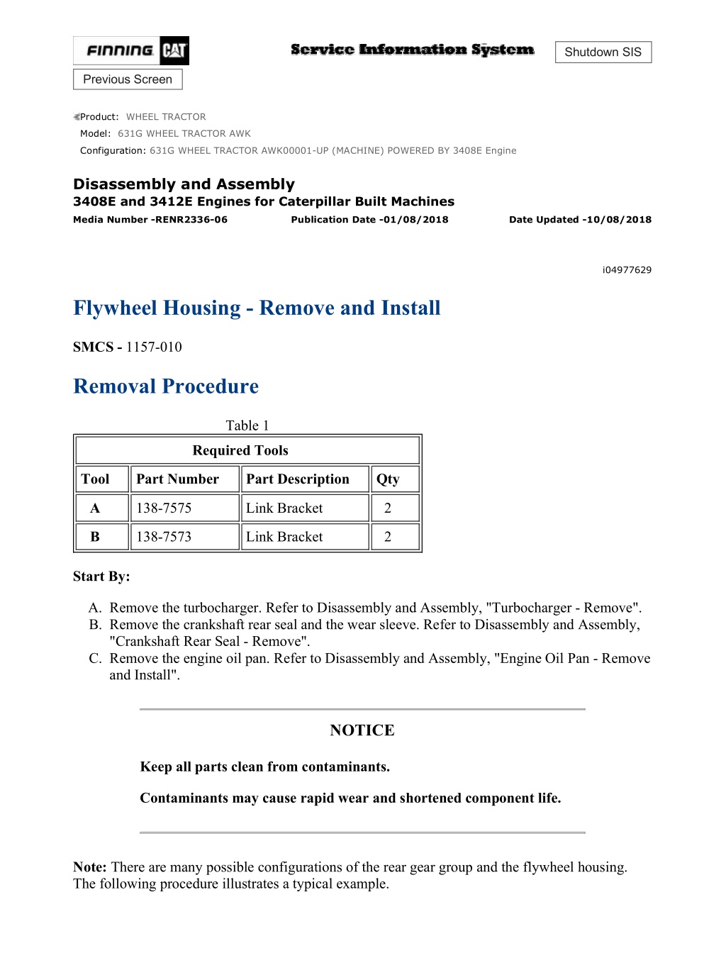
w 1/14(W) Shutdown SIS Previous Screen Product: WHEEL TRACTOR Model: 631G WHEEL TRACTOR AWK Configuration: 631G WHEEL TRACTOR AWK00001-UP (MACHINE) POWERED BY 3408E Engine Disassembly and Assembly 3408E and 3412E Engines for Caterpillar Built Machines Media Number -RENR2336-06 Publication Date -01/08/2018 Date Updated -10/08/2018 i04977629 Flywheel Housing - Remove and Install SMCS - 1157-010 Removal Procedure Table 1 Required Tools Tool Part Number Part Description Qty A 138-7575 Link Bracket 2 B 138-7573 Link Bracket 2 Start By: A. Remove the turbocharger. Refer to Disassembly and Assembly, "Turbocharger - Remove". B. Remove the crankshaft rear seal and the wear sleeve. Refer to Disassembly and Assembly, "Crankshaft Rear Seal - Remove". C. Remove the engine oil pan. Refer to Disassembly and Assembly, "Engine Oil Pan - Remove and Install". NOTICE Keep all parts clean from contaminants. Contaminants may cause rapid wear and shortened component life. Note: There are many possible configurations of the rear gear group and the flywheel housing. The following procedure illustrates a typical example. https://127.0.0.1/sisweb/sisweb/techdoc/techdoc_print_page.jsp?returnurl=/sisweb/sisw... 2021/6/17
w 2/14(W) Illustration 1 g00585225 Typical example 1. Remove exhaust clamp (1) from the right side of the engine. Illustration 2 g00585471 Typical example 2. Remove exhaust clamp (2) from the left side of the engine. https://127.0.0.1/sisweb/sisweb/techdoc/techdoc_print_page.jsp?returnurl=/sisweb/sisw... 2021/6/17
w 3/14(W) Illustration 3 g00585475 Typical example 3. Remove bolts (6), cover (3), bolts (7), cover (4), bolts (8), cover (5), and the gaskets. Illustration 4 g00585472 Typical example 4. Remove bolts (9) . https://127.0.0.1/sisweb/sisweb/techdoc/techdoc_print_page.jsp?returnurl=/sisweb/sisw... 2021/6/17
https://www.ebooklibonline.com Hello dear friend! Thank you very much for reading. Enter the link into your browser. The full manual is available for immediate download. https://www.ebooklibonline.com
w 4/14(W) Illustration 5 g00585510 Typical example 5. Install Tools (A), and a suitable lifting device to adapter assembly (11) . 6. Use the correct sized forcing screws (10) in order to separate adapter assembly (11) from the flywheel housing. The weight of the adapter assembly is approximately 31 kg (68 lb). Illustration 6 g00585514 Typical example 7. Remove two nuts (14) and the washers. 8. Remove adapter assembly (15) . https://127.0.0.1/sisweb/sisweb/techdoc/techdoc_print_page.jsp?returnurl=/sisweb/sisw... 2021/6/17
w 5/14(W) Illustration 7 g00585525 Typical example 9. Remove O-ring seal (16) from adapter assembly (15), if necessary. Illustration 8 g00585528 Typical example 10. Remove pin (20), bolts (18), washer (17), and gear (19) from adapter assembly (15), if necessary. https://127.0.0.1/sisweb/sisweb/techdoc/techdoc_print_page.jsp?returnurl=/sisweb/sisw... 2021/6/17
w 6/14(W) Illustration 9 g00585611 Typical example 11. Remove bolts (21) from adapter assembly (22) . Illustration 10 g00585651 Typical example 12. Install Tools (A). Attach a suitable lifting device to adapter assembly (22) . 13. Use the correct sized forcing screws (10) in order to remove adapter assembly (22) . https://127.0.0.1/sisweb/sisweb/techdoc/techdoc_print_page.jsp?returnurl=/sisweb/sisw... 2021/6/17
w 7/14(W) Illustration 11 g00585657 Typical example 14. Install Tools (B). Attach a suitable lifting device to flywheel housing (23) . The weight of the flywheel housing is approximately 160 kg (350 lb). 15. Remove hose assembly (24) . 16. Remove bolts (25) . 17. Remove flywheel housing (23) . 18. Remove all of the gasket material from the flywheel housing and the cylinder block. Installation Procedure Table 2 Required Tools Tool Part Number Part Description Qty A 138-7575 Link Bracket 1 B 138-7573 Link Bracket 2 C - Loctite 596 - NOTICE Keep all parts clean from contaminants. Contaminants may cause rapid wear and shortened component life. https://127.0.0.1/sisweb/sisweb/techdoc/techdoc_print_page.jsp?returnurl=/sisweb/sisw... 2021/6/17
w 8/14(W) Note: There are many possible configurations of the rear gear group and the flywheel housing. The following procedure illustrates a typical example. Note: Check the condition of the O-ring seals. If the O-ring seals are worn or damaged, use new parts for replacement. Note: Use new gaskets for installation. 1. Install a new gasket on the cylinder block. Note: Do not use a gasket adhesive or any other type of sealant on the gasket. All of the mating surfaces must be free of contaminants. Illustration 12 g00585840 Typical example 2. Install Tools (B). Attach a suitable lifting device to flywheel housing (23) . The weight of the flywheel housing is approximately 160 kg (350 lb). 3. Remove plug (26) . https://127.0.0.1/sisweb/sisweb/techdoc/techdoc_print_page.jsp?returnurl=/sisweb/sisw... 2021/6/17
w 9/14(W) Illustration 13 g00585851 Typical example 4. Place flywheel housing (23) in position. Use hole (27) in order to make an alignment of the "V" marks on the balancer gear and the rear crankshaft gear. Make sure to have the number one cylinder at top center. 5. Install bolts (25) . Illustration 14 g02427957 Note: Discard bolts used in locations (15) and (16). Use new bolts in these two locations. 6. Use the following torque sequence: https://127.0.0.1/sisweb/sisweb/techdoc/techdoc_print_page.jsp?returnurl=/sisweb/sisw... 2021/6/17
w 10/14(W) a. Torque bolts 1 thru 21 in numerical sequence to 40 7 N m (30 5 lb ft). b. Torque bolt 1 thru 8 in numerical sequence to 135 15 N m (100 11 lb ft). c. Torque bolts 9 thru 21 in numerical sequence to 50 10 N m (37 7 lb ft). 7. Install hose assembly (24) . 8. Install plug (19) with Tooling (C) on the threads of the plug. 9. Tighten the bolts to the correct torque in the correct numerical sequence. Refer to Specifications, "Flywheel Housing" for the correct tightening procedure. Illustration 15 g00585955 Typical example 10. Install Tool (A) in adapter assembly (11). Use a suitable lifting device for lifting the adapter assembly. The weight of the adapter assembly is approximately 31 kg (68 lb). 11. Install the gasket for the adapter assembly. Position the adapter assembly on the flywheel housing. 12. Install washer (13) and bolts (12) . 13. Install bolts (9) . https://127.0.0.1/sisweb/sisweb/techdoc/techdoc_print_page.jsp?returnurl=/sisweb/sisw... 2021/6/17
w 11/14(W) Illustration 16 g00585960 Typical example 14. Install adapter assembly (22). Repeat Steps 10 through 13. Illustration 17 g00585528 Typical example 15. Install pin (20), bolts (18), washer (17), and gear (19) in adapter assembly (15), if the parts were removed. 16. Install the O-ring seal on adapter assembly (15) . https://127.0.0.1/sisweb/sisweb/techdoc/techdoc_print_page.jsp?returnurl=/sisweb/sisw... 2021/6/17
w 12/14(W) Illustration 18 g00585514 Typical example 17. Install adapter (15). Install nuts (14) . Illustration 19 g00585475 Typical example 18. Position cover (3) and cover (4) on the flywheel housing. Install bolts (6) and bolts (8) . 19. Position cover (4) on the flywheel housing. Install bolts (7) . https://127.0.0.1/sisweb/sisweb/techdoc/techdoc_print_page.jsp?returnurl=/sisweb/sisw... 2021/6/17
w 13/14(W) Illustration 20 g00585471 Typical example 20. Install exhaust clamp (2). Tighten the clamp to a torque of 7.5 1.0 N m (66 9 lb in). Tighten the clamp again after the engine has been run. Illustration 21 g00585225 Typical example 21. Install exhaust clamp (1). Tighten the clamp to a torque of 7.5 1.0 N m (66 9 lb in). Tighten the clamp again after the engine has been run. End By: a. Install the engine oil pan. Refer to Disassembly and Assembly, "Engine Oil Pan - Remove and Install". b. Install the crankshaft rear seal. Refer to Disassembly and Assembly, "Crankshaft Rear Seal - Install". c. Install the turbocharger. Refer to Disassembly and Assembly, "Turbocharger - Install". Copyright 1993 - 2021 Caterpillar Inc. Thu Jun 17 09:20:04 UTC+0800 2021 All Rights Reserved. https://127.0.0.1/sisweb/sisweb/techdoc/techdoc_print_page.jsp?returnurl=/sisweb/sisw... 2021/6/17
w 1/4(W) Shutdown SIS Previous Screen Product: WHEEL TRACTOR Model: 631G WHEEL TRACTOR AWK Configuration: 631G WHEEL TRACTOR AWK00001-UP (MACHINE) POWERED BY 3408E Engine Disassembly and Assembly 3408E and 3412E Engines for Caterpillar Built Machines Media Number -RENR2336-06 Publication Date -01/08/2018 Date Updated -10/08/2018 i01364167 Vibration Damper and Pulley - Remove and Install SMCS - 1205-010 Removal Procedure Table 1 Tool Part Number Part Description Qty A - 5/8 inch-NF X 7 inch long guide bolt 2 Illustration 1 g00719482 1. Install a nylon strap and a hoist on pulley (2). 2. Remove two bolts (1) and install Tool (A). 3. Remove the remainder of the bolts (1). 4. Remove pulley (2). Weight of the pulley is 32 kg (71 lb). https://127.0.0.1/sisweb/sisweb/techdoc/techdoc_print_page.jsp?returnurl=/sisweb/sisw... 2021/6/17
w 2/4(W) Illustration 2 g00719530 5. Remove vibration damper (3). Illustration 3 g00719523 6. Remove spacer (4) and adapter (5). Installation Procedure Table 2 Tool Part Number Part Description Qty A - 5/8 inch-NF X 7 inch long guide bolt 2 https://127.0.0.1/sisweb/sisweb/techdoc/techdoc_print_page.jsp?returnurl=/sisweb/sisw... 2021/6/17
w 3/4(W) Illustration 4 g00719523 1. Install Tool (A) in the crankshaft. 2. Install adapter (5) and spacer (4). Illustration 5 g00719530 3. Install vibration damper (3). Illustration 6 g00719482 4. Install pulley (2). https://127.0.0.1/sisweb/sisweb/techdoc/techdoc_print_page.jsp?returnurl=/sisweb/sisw... 2021/6/17
w 4/4(W) 5. Lightly lubricate the bolt threads with clean engine oil. Install four bolts (1). Remove Tool (A). Install the last two bolts. Tighten bolts (1) to a torque of 215 40 N m (159 30 lb ft). Copyright 1993 - 2021 Caterpillar Inc. Thu Jun 17 09:21:00 UTC+0800 2021 All Rights Reserved. Private Network For SIS Licensees. https://127.0.0.1/sisweb/sisweb/techdoc/techdoc_print_page.jsp?returnurl=/sisweb/sisw... 2021/6/17
w 1/4(W) Shutdown SIS Previous Screen Product: WHEEL TRACTOR Model: 631G WHEEL TRACTOR AWK Configuration: 631G WHEEL TRACTOR AWK00001-UP (MACHINE) POWERED BY 3408E Engine Disassembly and Assembly 3408E and 3412E Engines for Caterpillar Built Machines Media Number -RENR2336-06 Publication Date -01/08/2018 Date Updated -10/08/2018 i01622074 Crankshaft Front Seal - Remove SMCS - 1160-011 Removal Procedure Table 1 Required Tools Tool Part Number Part Description Qty A 1U-7600 Slide Hammer Puller 1 B (1) 5P-7314 Distorter Ring 1 C (1) 5P-7312 Seal Distorter 1 ( 1 ) Part of the 5P-7318 Wear Sleeve Distorter Group Start By: A. Remove the vibration damper and the pulley. Refer to Disassembly and Assembly, "Vibration Damper and Pulley - Remove and Install". NOTICE Keep all parts clean from contaminants. Contaminants may cause rapid wear and shortened component life. Note: The front seal and the wear sleeve must be replaced at the same time. Once the seal and the wear sleeve are separated, these components can not be used again. Refer to Special Instruction, https://127.0.0.1/sisweb/sisweb/techdoc/techdoc_print_page.jsp?returnurl=/sisweb/sisw... 2021/6/17
w 2/4(W) SMHS8508, "Special Handling Information and Installation Instructions for Crankshaft Seal Groups That Have Hydrodynamic Grooves In the Sealing Lip" before the seal is serviced. Type 1 Illustration 1 g00829187 Type 1 seal design. (1) Seal (2) Wear sleeve https://127.0.0.1/sisweb/sisweb/techdoc/techdoc_print_page.jsp?returnurl=/sisweb/sisw... 2021/6/17
w 3/4(W) Illustration 2 g00582156 Typical example 1. Use a punch or Tool (A) to puncture a hole in seal (1). Use Tool (A) to remove seal (1) . Illustration 3 g00582158 Typical example 2. Place Tool (B) in position. The correct position is shown in Illustration 3. 3. Install Tool (C) between Tool (B) and the wear sleeve. Turn Tool (C), until the edge of the tool makes a flat crease in the wear sleeve. Repeat this procedure until there are enough creases in the wear sleeve in order to allow the wear sleeve to be slipped off the end of the crankshaft. 4. Remove Tool (B) and the wear sleeve by hand. Type 2 https://127.0.0.1/sisweb/sisweb/techdoc/techdoc_print_page.jsp?returnurl=/sisweb/sisw... 2021/6/17
w 4/4(W) Illustration 4 g00829143 New seal design (1) Seal (2) Wear sleeve flange (3) Wear sleeve 1. Use a hammer and a punch in order to puncture 3 holes in the wear sleeve (3) on the flange of the wear sleeve (2). Use Tool (A) to remove the wear sleeve (3) . 2. Use a punch or Tool (A) to puncture a hole in seal (1). Use Tool (A) to remove seal (1) . Copyright 1993 - 2021 Caterpillar Inc. Thu Jun 17 09:21:56 UTC+0800 2021 All Rights Reserved. Private Network For SIS Licensees. https://127.0.0.1/sisweb/sisweb/techdoc/techdoc_print_page.jsp?returnurl=/sisweb/sisw... 2021/6/17
w 1/6(W) Shutdown SIS Previous Screen Product: WHEEL TRACTOR Model: 631G WHEEL TRACTOR AWK Configuration: 631G WHEEL TRACTOR AWK00001-UP (MACHINE) POWERED BY 3408E Engine Disassembly and Assembly 3408E and 3412E Engines for Caterpillar Built Machines Media Number -RENR2336-06 Publication Date -01/08/2018 Date Updated -10/08/2018 i01655980 Crankshaft Front Seal - Install SMCS - 1160-012 Installation Procedure Type 1 Table 1 Required Tools Tool Part Number Part Description Qty A 5P-1733 Seal Locator 1 B 5P-1737 Bolts 3 C 9S-8858 Nut (Seal Installer) 1 D 6V-6142 Front Seal Installer 1 NOTICE Keep all parts clean from contaminants. Contaminants may cause rapid wear and shortened component life. Note: The front seal and the wear sleeve must be replaced at the same time. Once the seal and the wear sleeve are separated, these components cannot be used again. Refer to Special Instruction, SMHS8508, "Special Handling Information and Installation Instructions for Crankshaft Seal Groups That Have Hydrodynamic Grooves In the Sealing Lip" before the seal is serviced. https://127.0.0.1/sisweb/sisweb/techdoc/techdoc_print_page.jsp?returnurl=/sisweb/sisw... 2021/6/17
w 2/6(W) Note: Do not use any type of lubricant during the installation of the crankshaft seal and the wear sleeve. 1. Before installation of the crankshaft seal and the wear sleeve, inspect the crankshaft for scratches. Also, inspect the crankshaft for any distortion on the surface that may lead to an out of round condition. Use a polishing cloth in order to remove any imperfections on the crankshaft. 2. Use 4C-9500 Quick Cure Primer to clean the outside diameter of the crankshaft and the inside diameter of wear sleeve (1). 3. Apply 4C-9507 Retaining Compound to the outside diameter of the crankshaft. Apply 4C- 9507 Retaining Compound to the inside diameter of wear sleeve (1). Illustration 1 g00829187 Type 1 seal design. (1) Seal (2) Wear sleeve https://127.0.0.1/sisweb/sisweb/techdoc/techdoc_print_page.jsp?returnurl=/sisweb/sisw... 2021/6/17
w 3/6(W) Illustration 2 g00829675 Typical example 4. Fasten Tool (A) to the crankshaft with Tool (B). NOTICE The front and rear seals and wear sleeves have different spiral grooves in the seal. Because of this type of design, the front seal group for an engine is different from the rear seal group. If a seal group is installed on the wrong end of the engine, oil can actually be taken out of the engine instead of moving oil back into the engine. Illustration 3 g00515623 Note: Install the seal with the arrow that shows the direction of crankshaft rotation toward the front of the engine. https://127.0.0.1/sisweb/sisweb/techdoc/techdoc_print_page.jsp?returnurl=/sisweb/sisw... 2021/6/17
w 4/6(W) 5. Position wear sleeve (2) and seal (1) on Tool (A). Install Tool (D) on Tool (A). Lubricate the face of the washer on Tool (C). Install Tool (C) on Tool (A). 6. Tighten Tool (C) until Tool (D) contacts Tool (A). 7. Remove Tools (A), (B), (C), and (D). Check the crankshaft seal and the wear sleeve for the correct installation. Type 2 Table 2 Required Tools Tool Part Number Part Description Qty A 5P-1733 Seal Locator 1 B 5P-1737 Bolts 3 C 9S-8858 Nut (Seal Installer) 1 D 6V-6142 Front Seal Installer 1 NOTICE Keep all parts clean from contaminants. Contaminants may cause rapid wear and shortened component life. Note: The front seal and the wear sleeve must be replaced at the same time. Once the seal and the wear sleeve are separated, these components cannot be used again. Refer to Special Instruction, SMHS8508, "Special Handling Information and Installation Instructions for Crankshaft Seal Groups That Have Hydrodynamic Grooves In the Sealing Lip" before the seal is serviced. Note: Do not use any type of lubricant during the installation of the crankshaft seal and the wear sleeve. 1. Before installation of the crankshaft seal and the wear sleeve, inspect the crankshaft for scratches. Also, inspect the crankshaft for any distortion on the surface that may lead to an out of round condition. Use a polishing cloth in order to remove any imperfections on the crankshaft. 2. Use 4C-9500 Quick Cure Primer to clean the outside diameter of the crankshaft. Note: The type 2 seal comes with the 4C-9507 Retaining Compound that is already applied to the inside diameter of the wear sleeve. https://127.0.0.1/sisweb/sisweb/techdoc/techdoc_print_page.jsp?returnurl=/sisweb/sisw... 2021/6/17
w 5/6(W) Illustration 4 g00829143 Type 2 seal design. (1) Seal (2) Wear sleeve flange (3) Wear sleeve Illustration 5 g00829675 Typical example 3. Fasten Tool (A) to the crankshaft with Tool (B). NOTICE https://127.0.0.1/sisweb/sisweb/techdoc/techdoc_print_page.jsp?returnurl=/sisweb/sisw... 2021/6/17
w 6/6(W) The front and rear seals and wear sleeves have different spiral grooves in the seal. Because of this type of design, the front seal group for an engine is different from the rear seal group. If a seal group is installed on the wrong end of the engine, oil can actually be taken out of the engine instead of moving oil back into the engine. Illustration 6 g00515623 Note: Install the seal with the arrow that shows the direction of crankshaft rotation toward the front of the engine. 4. Position wear sleeve (2) and seal (1) on Tool (A). Install Tool (D) on Tool (A). Lubricate the face of the washer on Tool (C). Install Tool (C) on Tool (A). 5. Tighten Tool (C) until Tool (D) contacts Tool (A). 6. Remove Tools (A), (B), (C), and (D). Check the crankshaft seal and the wear sleeve for the correct installation. End By: a. Install the vibration damper and the pulley. Refer to Disassembly and Assembly, "Vibration Damper and Pulley - Remove and Install". Copyright 1993 - 2021 Caterpillar Inc. Thu Jun 17 09:22:52 UTC+0800 2021 All Rights Reserved. Private Network For SIS Licensees. https://127.0.0.1/sisweb/sisweb/techdoc/techdoc_print_page.jsp?returnurl=/sisweb/sisw... 2021/6/17
Suggest: If the above button click is invalid. Please download this document first, and then click the above link to download the complete manual. Thank you so much for reading
w 1/3(W) Shutdown SIS Previous Screen Product: WHEEL TRACTOR Model: 631G WHEEL TRACTOR AWK Configuration: 631G WHEEL TRACTOR AWK00001-UP (MACHINE) POWERED BY 3408E Engine Disassembly and Assembly 3408E and 3412E Engines for Caterpillar Built Machines Media Number -RENR2336-06 Publication Date -01/08/2018 Date Updated -10/08/2018 i02160179 Gear Group (Front) - Remove SMCS - 1206-011 Removal Procedure Table 1 Required Tools Tool Part Number Part Description Qty A 1P-0510 Driver Group 1 Start By: a. Remove the camshaft. Refer to Disassembly and Assembly, "Camshaft - Remove". NOTICE Keep all parts clean from contaminants. Contaminants may cause rapid wear and shortened component life. NOTICE Care must be taken to ensure that fluids are contained during performance of inspection, maintenance, testing, adjusting, and repair of the product. Be prepared to collect the fluid with suitable containers before opening any compartment or disassembling any component containing fluids. https://127.0.0.1/sisweb/sisweb/techdoc/techdoc_print_page.jsp?returnurl=/sisweb/sisw... 2021/6/17
https://www.ebooklibonline.com Hello dear friend! Thank you very much for reading. Enter the link into your browser. The full manual is available for immediate download. https://www.ebooklibonline.com