Caterpillar Cat 212 WHEEL-TYPE EXCAVATOR (Prefix 5DC) Service Repair Manual Instant Download
Please open the website below to get the complete manualnn//

Download Presentation

Please find below an Image/Link to download the presentation.
The content on the website is provided AS IS for your information and personal use only. It may not be sold, licensed, or shared on other websites without obtaining consent from the author. Download presentation by click this link. If you encounter any issues during the download, it is possible that the publisher has removed the file from their server.
E N D
Presentation Transcript
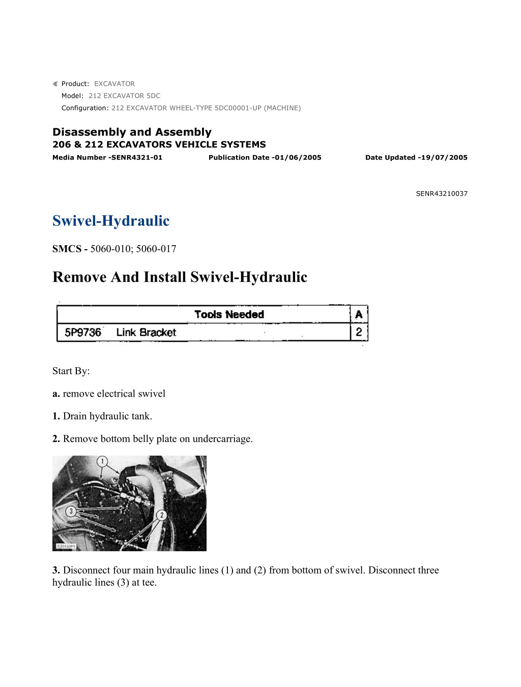
212 EXCAVATOR WHEEL-TYPE 5DC00001-UP (MACHINE)(HMBP1496 - 04) - ... 1/5 Product: EXCAVATOR Model: 212 EXCAVATOR 5DC Configuration: 212 EXCAVATOR WHEEL-TYPE 5DC00001-UP (MACHINE) Disassembly and Assembly 206 & 212 EXCAVATORS VEHICLE SYSTEMS Media Number -SENR4321-01 Publication Date -01/06/2005 Date Updated -19/07/2005 SENR43210037 Swivel-Hydraulic SMCS - 5060-010; 5060-017 Remove And Install Swivel-Hydraulic Start By: a. remove electrical swivel 1. Drain hydraulic tank. 2. Remove bottom belly plate on undercarriage. 3. Disconnect four main hydraulic lines (1) and (2) from bottom of swivel. Disconnect three hydraulic lines (3) at tee. https://127.0.0.1/sisweb/sisweb/techdoc/techdoc_print_page.jsp?returnurl=/sis... 2021/10/16
212 EXCAVATOR WHEEL-TYPE 5DC00001-UP (MACHINE)(HMBP1496 - 04) - ... 2/5 4. Disconnect six hydraulic lines (4). Remove four bolts (5) and secure bracket and lines back out of the way. 5. Remove four main hydraulic lines (6) from top of swivel. Remove two hydraulic lines (7) from swivel. Disconnect hydraulic hose (8). 6. Attach tooling (A) and remove three bolts (9). Remove swivel. The weight of the swivel is 64 kg (140 lb). NOTE: The following steps are for the installation of the swivel. 7. Position swivel in excavator and install three bolts (9). 8. Connect hydraulic hose (8). Attach two hydraulic lines (7) to swivel. Attach four main hydraulic lines (6) to top of swivel. 9. Install four bolts (5) and connect six hydraulic lines (4). 10. On bottom of swivel install three hydraulic lines (3) and four main hydraulic lines (1) and (2). 11. Install bottom belly plate on undercarriage. 12. Fill hydraulic tank. End By: a. install electrical swivel https://127.0.0.1/sisweb/sisweb/techdoc/techdoc_print_page.jsp?returnurl=/sis... 2021/10/16
212 EXCAVATOR WHEEL-TYPE 5DC00001-UP (MACHINE)(HMBP1496 - 04) - ... 3/5 Disassemble And Assemble Swivel-Hydraulic Start By: a. remove swivel NOTE: The following photos and text is TYPICAL and is not meant as an exact illustration for the disassembly of the 206 or 212 Swivel. However, the same procedures do apply. 1. Remove two hydraulic fittings (1) and (3) from cover (2). 2. Remove four bolts (4) and remove cover (2). 3. Remove two bolts (8) and remove cover (7). 4. Remove two bolts (5) and bracket (6). Remove three bolts and cover (9). 5. Remove small swivel housing (12) from rotor (11). 6. Remove four set screws (10) and rotor (11). https://127.0.0.1/sisweb/sisweb/techdoc/techdoc_print_page.jsp?returnurl=/sis... 2021/10/16
https://www.ebooklibonline.com Hello dear friend! Thank you very much for reading. Enter the link into your browser. The full manual is available for immediate download. https://www.ebooklibonline.com
212 EXCAVATOR WHEEL-TYPE 5DC00001-UP (MACHINE)(HMBP1496 - 04) - ... 4/5 7. Attach tooling (A) to housing (13) and carefully separate housing (13) from rotor (14). 8. Remove seal ring (15), five washer seals (16) and one ring (17) from swivel housing (13). 9. From small swivel housing (12) remove wiper (18), seal (19), flat rubber seal (20), ring (21), seal (22) and wiper (23). NOTE: The following steps are to assemble the swivel. https://127.0.0.1/sisweb/sisweb/techdoc/techdoc_print_page.jsp?returnurl=/sis... 2021/10/16
212 EXCAVATOR WHEEL-TYPE 5DC00001-UP (MACHINE)(HMBP1496 - 04) - ... 5/5 10. In the small swivel housing (12), install wiper (23), seal (22), ring (21), flat rubber seal (20), seal (19) and wiper (18). 11. In swivel housing (13), install ring (17), five washer seals (16) and ring (15). 12. With tooling (A) slide housing (13) over rotor (14). 13. Install cover (9) with three bolts. Install rotor (11), small swivel (12) and secure with four set screws (10). 14. Install cover (7) with two bolts (8). 15. Install bracket (6) with two bolts (5). 16. Install cover (2) with four bolts (4). 17. Install hydraulic fittings (3) and (1). End By: a. install swivel https://127.0.0.1/sisweb/sisweb/techdoc/techdoc_print_page.jsp?returnurl=/sis... 2021/10/16
212 EXCAVATOR WHEEL-TYPE 5DC00001-UP (MACHINE)(HMBP1496 - 04) - ... 1/7 Product: EXCAVATOR Model: 212 EXCAVATOR 5DC Configuration: 212 EXCAVATOR WHEEL-TYPE 5DC00001-UP (MACHINE) Disassembly and Assembly 206 & 212 EXCAVATORS VEHICLE SYSTEMS Media Number -SENR4321-01 Publication Date -01/06/2005 Date Updated -19/07/2005 SENR43210038 Duo-Cone Seals SMCS - 7561-016 Assembly And Installation Of Conventional Duo-Cone Seals Introduction This instruction gives the procedure for installing Conventional Duo-Cone Seals. It is most important that correct assembly and installation procedures are followed when Duo- Cone Seals are used. Many of the Duo-Cone Seals failures are the direct result of one or more mistakes made during assembly or installation of the seal components. NOTICE Keep all parts clean from contaminants. Contaminants put into the system may cause rapid wear and shortened component life. https://127.0.0.1/sisweb/sisweb/techdoc/techdoc_print_page.jsp?returnurl=/sis... 2021/10/16
212 EXCAVATOR WHEEL-TYPE 5DC00001-UP (MACHINE)(HMBP1496 - 04) - ... 2/7 (1) Seal (2) Rubber Toric Ring (3) Housing Retaining Lip (4) Housing Ramp (5) Seal Ring Housing (6) Seal Ring Face (7) Seal Ring Ramp (8) Seal Ring Retaining Lip (9) Installation Tool. NOTICE Never permit oil to get on the toric rings or ramps before both seal rings are put together in their final assembled position (Step 10). https://127.0.0.1/sisweb/sisweb/techdoc/techdoc_print_page.jsp?returnurl=/sis... 2021/10/16
212 EXCAVATOR WHEEL-TYPE 5DC00001-UP (MACHINE)(HMBP1496 - 04) - ... 3/7 Avoid prolonged skin contact with isopropyl alcohol. Avoid breathing the vapors in enclosed areas without adequate ventilation and do not smoke. Do no use near open flame or welding operations or other heated surfaces exceeding 482 C (900 F). 1. Use isopropyl alcohol with a clean cloth or paper towels to remove any oil film, dust or other foreign matter from toric rubber rings (2) and from ramps (4) and (7) and lips (3) and (8) of both seal rings (1) and housings (5). 2. Put toric ring (2) on seal ring (1), at the bottom of seal ring ramp (7) and against retaining lip (8). NOTICE https://127.0.0.1/sisweb/sisweb/techdoc/techdoc_print_page.jsp?returnurl=/sis... 2021/10/16
212 EXCAVATOR WHEEL-TYPE 5DC00001-UP (MACHINE)(HMBP1496 - 04) - ... 4/7 Make sure that toric ring (2) is straight on seal ring (1) and is not twisted. Be careful when you work on the rubber toric ring. Nicks, cuts and scratches can cause leaks. NOTICE Do not use Stanisol or any other liquid that leaves an oil film or does not evaporate quickly. 3. Put installation tool (9) onto seal ring (1) with toric ring (2). Lower the rings into a container with isopropyl alcohol until all surfaces of toric ring (2) are wet. https://127.0.0.1/sisweb/sisweb/techdoc/techdoc_print_page.jsp?returnurl=/sis... 2021/10/16
212 EXCAVATOR WHEEL-TYPE 5DC00001-UP (MACHINE)(HMBP1496 - 04) - ... 5/7 4. With all surface of toric ring (2) wet, us installation tool (9) to position seal ring (1) and toric ring (2) squarely against housing (5) as shown. Use sudden and even pressure to pop (push) toric ring (2), under retaining lip (3) of housing (5). 5. Check assembled height (A) in at least four places, 90 apart. The difference in height around the ring must not be more than 1 mm (.04"). 6. If small adjustments are necessary, do not push directly on seal ring (1); use installation tool (9). 7. Toric ring (2) can twist if it is not wet all around during installation or if there are burrs or fins on retaining lip (3) of housing (5). NOTICE Misalignment, twists and bulges of the toric ring will cause Duo-Cone Seal failures. If correct installation is not obvious, remove seal from housing and repeat steps 3 thru 6. IMPORTANT: Toric rings (2) must never slip on the ramps of either seal rings (1) or seal ring housings (5). To prevent slippage, wait a minimum of two minutes to let the isopropyl alcohol evaporate before further assembly. Once correctly in place, the toric ring must roll on the ramps only. https://127.0.0.1/sisweb/sisweb/techdoc/techdoc_print_page.jsp?returnurl=/sis... 2021/10/16
212 EXCAVATOR WHEEL-TYPE 5DC00001-UP (MACHINE)(HMBP1496 - 04) - ... 6/7 8. Wipe seal faces (6) of seal rings (1) clean. Use a lint free cloth or paper towel. No particles of any kind are permissible on the sealing surfaces. Even a small piece from a paper towel can hold the seal faces apart and cause leakage. https://127.0.0.1/sisweb/sisweb/techdoc/techdoc_print_page.jsp?returnurl=/sis... 2021/10/16
212 EXCAVATOR WHEEL-TYPE 5DC00001-UP (MACHINE)(HMBP1496 - 04) - ... 7/7 9. Use an applicator, a disposable tissue or a clean finger, to distribute a thin film of clean oil evenly on the seal faces. Do not to get any oil on the rubber toric rings. 10. Make sure both housings (5) are in correct alignment and are concentric. Move the parts slowly and carefully toward each other. NOTICE Do not slam seals together. High impact can scratch or break the seal components. 11. Once in place, fasten all parts tightly. https://127.0.0.1/sisweb/sisweb/techdoc/techdoc_print_page.jsp?returnurl=/sis... 2021/10/16
212 EXCAVATOR WHEEL-TYPE 5DC00001-UP (MACHINE)(HMBP1496 - 04) - ... 1/3 Product: EXCAVATOR Model: 212 EXCAVATOR 5DC Configuration: 212 EXCAVATOR WHEEL-TYPE 5DC00001-UP (MACHINE) Disassembly and Assembly 206 & 212 EXCAVATORS VEHICLE SYSTEMS Media Number -SENR4321-01 Publication Date -01/06/2005 Date Updated -19/07/2005 SENR43210039 Steering Cylinder SMCS - 7561-016 Remove And Install Steering Cylinder 1. Using tool (A) and (B), disconnect tie rod from steering cylinder rod. 2. Disconnect and plug two hydraulic lines (1). Remove eight bolts (3) and two end caps (2). https://127.0.0.1/sisweb/sisweb/techdoc/techdoc_print_page.jsp?returnurl=/sis... 2021/10/16
212 EXCAVATOR WHEEL-TYPE 5DC00001-UP (MACHINE)(HMBP1496 - 04) - ... 2/3 3. Remove cylinder rod (4) and O-ring (5). 4. Remove retaining ring (6). 5. Remove two sets of split rings (7) from each side of the piston. 6. Remove ring (8) and remove rod (4) from piston. 7. Remove seal (9), seal (10) and ring (11). https://127.0.0.1/sisweb/sisweb/techdoc/techdoc_print_page.jsp?returnurl=/sis... 2021/10/16
212 EXCAVATOR WHEEL-TYPE 5DC00001-UP (MACHINE)(HMBP1496 - 04) - ... 3/3 8. Inspect cylinder (12) and replace liner if necessary. NOTE: The following steps are for to install the steering cylinder. 9. Install seal (9), seal (10) and ring (11). 10. Slide rod (4) into piston and install ring (8). 11. Install two sets of split rings (7) on each side of piston. (A small amount of grease will hold rings in place in the groove). 12. Install retaining ring (6). 13. Slide piston and rod (4) assembly into cylinder and install two new O-ring seals (5). 14. Replace two end caps (2) and secure with eight bolts (3). 15. Connect two hydraulic lines (1) and connect two tie rods to cylinder rod ends with tools (A) and (B). NOTE: See Specification Service Manual for correct procedure to adjust the tie rods and the maximum steer angle. https://127.0.0.1/sisweb/sisweb/techdoc/techdoc_print_page.jsp?returnurl=/sis... 2021/10/16
212 EXCAVATOR WHEEL-TYPE 5DC00001-UP (MACHINE)(HMBP1496 - 04) - ... 1/3 Product: EXCAVATOR Model: 212 EXCAVATOR 5DC Configuration: 212 EXCAVATOR WHEEL-TYPE 5DC00001-UP (MACHINE) Disassembly and Assembly 206 & 212 EXCAVATORS VEHICLE SYSTEMS Media Number -SENR4321-01 Publication Date -01/06/2005 Date Updated -19/07/2005 SENR43210040 Steering Knuckle And Bearings SMCS - 4321-010 Remove And Install Steering Knuckle And Bearings Start By: a. remove front final drive (see 206 & 212 Disassembly And Assembly, Power Train, SENR4322) 1. Remove eight bolts (1) and two hydraulic lines (2). https://127.0.0.1/sisweb/sisweb/techdoc/techdoc_print_page.jsp?returnurl=/sis... 2021/10/16
212 EXCAVATOR WHEEL-TYPE 5DC00001-UP (MACHINE)(HMBP1496 - 04) - ... 2/3 2. Remove two bolts (3) and bracket (4). 3. Remove four bolts (5) and trunnion (6). 4. Attach tooling (A) and remove four bolts (7) and trunnion (8). 5. Remove knuckle (9). 6. Remove axle (10). 7. Remove seal (11). 8. Remove upper and lower cup bearings (12). 9. From trunnions (6) and (8), remove cone bearings (13). NOTE: The following steps are for the installation of the steering knuckle and bearings. https://127.0.0.1/sisweb/sisweb/techdoc/techdoc_print_page.jsp?returnurl=/sis... 2021/10/16
212 EXCAVATOR WHEEL-TYPE 5DC00001-UP (MACHINE)(HMBP1496 - 04) - ... 3/3 10. Install cone bearings (13) onto trunnions (6) and (8). 11. Install new upper and lower cup bearings (12). 12. Install new seal (11). 13. Install axle (10). 14. Position knuckle (9) to axle housing and install bottom trunnion (8) with four bolts (7). 15. Remove tooling (A) and install trunnion (6) with four bolts (5). NOTE: For proper bearing preload, see Specification Service Manual, and select appropriate shim from the parts book. 16. Install bracket (4) with two bolts (3). 17. Connect two hydraulic lines (2) with eight bolts (1). End By: a. install front final drive (see 206 & 212 Disassembly And Assembly, Power Train, SENR4322) https://127.0.0.1/sisweb/sisweb/techdoc/techdoc_print_page.jsp?returnurl=/sis... 2021/10/16
212 EXCAVATOR WHEEL-TYPE 5DC00001-UP (MACHINE)(HMBP1496 - 04) - ... 1/4 Product: EXCAVATOR Model: 212 EXCAVATOR 5DC Configuration: 212 EXCAVATOR WHEEL-TYPE 5DC00001-UP (MACHINE) Disassembly and Assembly 206 & 212 EXCAVATORS VEHICLE SYSTEMS Media Number -SENR4321-01 Publication Date -01/06/2005 Date Updated -19/07/2005 SENR43210041 Downshift Control Valve SMCS - 3178-017; 3178-010 Remove And Install Downshift Control Valve NOTE: The following steps show the down shift control valve being removed after the transmission and differential have been removed. The valve may be removed without removing the transmission and differential. Start By: a. remove axle b. remove drive motor c. remove transmission and differential 1. Mark and remove two hydraulic lines (1) and (2). Remove four bolts (3) and four nuts (4). Remove housing (5). https://127.0.0.1/sisweb/sisweb/techdoc/techdoc_print_page.jsp?returnurl=/sis... 2021/10/16
212 EXCAVATOR WHEEL-TYPE 5DC00001-UP (MACHINE)(HMBP1496 - 04) - ... 2/4 2. Loosen two locknuts (6) and remove two oil supply pistons (7). Remove plug (8) and centrifugal valve (9). Remove valve body (10) from shaft. 3. Remove centrifugal valve seat (13) from shaft. Remove retaining ring (14) and shims (12). Remove bearing carrier (11). NOTE: The following steps are to install the downshift control valve. 4. Install bearing carrier (11) with four nuts (4). 5. Install shims (12) and retaining (14). Adjust end play between shims (12) and retaining ring (14) to a maximum of .20 mm (.008 in) by adding or subtracting shims. 6. Install centrifugal valve seat (13) onto shaft. Use grease to hold it in place. 7. Replace valve body (10). be sure large collar of valve body is toward the transmission and differential. 8. Install right side oil supply piston (7) first to insure alignment of the valve. Torque to maximum 15 N m (11 lb ft). 9. Install left side oil supply piston (7) next to insure alignment of the valve. Torque to maximum 15 N m (11 lb ft). 10. Install two locknuts (6). Torque to a maximum 28 N m (21 lb ft). 11. Install centrifugal valve (9) and plug (8). Torque to maximum 46 N m (34 lb ft). 12. Place housing on transmission and differential and install four bolts (3). Torque to a maximum of 49 N m (36 lb ft). 13. Connect two hydraulic lines (1) and (2). End By: a. install transmission and differential https://127.0.0.1/sisweb/sisweb/techdoc/techdoc_print_page.jsp?returnurl=/sis... 2021/10/16
212 EXCAVATOR WHEEL-TYPE 5DC00001-UP (MACHINE)(HMBP1496 - 04) - ... 3/4 b. install drive motor c. install axle Disassemble And Assemble Downshift Control Valve Start By: a. remove downshift control valve 1. Remove retaining ring (1) and seal (2). Remove four hydraulic fittings (3). Check and replace O -ring seals if needed. 2. Remove plug (4), seal (5), bushing (6), piston (7), washer (8), keeper (9), washer (10), spring (11) and washer (12). 3. Remove plug (13), seal (14), spring (15) and piston (16). NOTE: The following steps are to assemble the downshift control valve. https://127.0.0.1/sisweb/sisweb/techdoc/techdoc_print_page.jsp?returnurl=/sis... 2021/10/16
212 EXCAVATOR WHEEL-TYPE 5DC00001-UP (MACHINE)(HMBP1496 - 04) - ... 4/4 4. Install piston (16), spring (15), seal (14), and plug (13). 5. Install washer (12), spring (11), washer (10), keeper (9), washer (8), piston (7), bushing (6), seal (5) and plug (4). 6. Install four hydraulic fittings (3). Install seal (2) with tool (A) and install retaining ring (1). End By: a. install downshift control valve https://127.0.0.1/sisweb/sisweb/techdoc/techdoc_print_page.jsp?returnurl=/sis... 2021/10/16
212 EXCAVATOR WHEEL-TYPE 5DC00001-UP (MACHINE)(HMBP1496 - 04) - ... 1/5 Product: EXCAVATOR Model: 212 EXCAVATOR 5DC Configuration: 212 EXCAVATOR WHEEL-TYPE 5DC00001-UP (MACHINE) Disassembly and Assembly 206 & 212 EXCAVATORS VEHICLE SYSTEMS Media Number -SENR4321-01 Publication Date -01/06/2005 Date Updated -19/07/2005 SENR43210042 Hydraulic Rotary Joint SMCS - 5060-017; 5060-010 Remove And Install Hydraulic Rotary Joint Start By: 1. Remove the access cover. Disconnect and plug seven hydraulic lines (1). 2. Disconnect and plug seven hydraulic lines (2). Loosen bolts (3) and remove three bolts (4). https://127.0.0.1/sisweb/sisweb/techdoc/techdoc_print_page.jsp?returnurl=/sis... 2021/10/16
212 EXCAVATOR WHEEL-TYPE 5DC00001-UP (MACHINE)(HMBP1496 - 04) - ... 2/5 3. Install tool (A) and attach to a hoist. Remove rotary joint (5). NOTE: Install in reverse order. Disassemble And Assemble Hydraulic Rotary Joint Start By: a. remove hydraulic rotary joint NOTICE Keep all parts clean from contaminants. Contaminants put into the system may cause rapid wear and shortened component life. 1. Remove two hydraulic fittings (1) and (3). 2. Remove four bolts (4) and remove cover (2). https://127.0.0.1/sisweb/sisweb/techdoc/techdoc_print_page.jsp?returnurl=/sis... 2021/10/16
Suggest: If the above button click is invalid. Please download this document first, and then click the above link to download the complete manual. Thank you so much for reading
212 EXCAVATOR WHEEL-TYPE 5DC00001-UP (MACHINE)(HMBP1496 - 04) - ... 3/5 3. Remove two bolts (8) and remove cover (7). 4. Remove two bolts (5) and bracket (6). Remove the three bolts and cover (9). 5. Remove small rotary joint housing (12). 6. Remove four set screws (10) and rotor (11). 7. Attach tooling (A) to housing (13) and carefully separate housing (13) from rotor (14). https://127.0.0.1/sisweb/sisweb/techdoc/techdoc_print_page.jsp?returnurl=/sis... 2021/10/16
https://www.ebooklibonline.com Hello dear friend! Thank you very much for reading. Enter the link into your browser. The full manual is available for immediate download. https://www.ebooklibonline.com
(HMBP1496 -")
(HMBP1496 -")
(HMBP1496 -")

(HMBP1496 -")
(HMBP1496 -")
(HMBP1496 -")
(HMBP1496 -")
(HMBP1496 -")
(HMBP1496 -")
(HMBP1496 -")
(HMBP1496 -")
(HMBP1496 -")
(HMBP1496 -")
(HMBP1496 -")
(HMBP1496 -")
(HMBP1496 -")
(HMBP1496 -")
(HMBP1496 -")
(HMBP1496 -")
(HMBP1496 -")
(HMBP1496 -")
(HMBP1496 -")
(HMBP1496 -")
(HMBP1496 -")

(HMBP1496 -")