Caterpillar Cat 206 EXCAVATOR WHEEL TYPE EXCAVATOR (Prefix 3GC) Service Repair Manual Instant Download
Please open the website below to get the complete manualnn//

Download Presentation

Please find below an Image/Link to download the presentation.
The content on the website is provided AS IS for your information and personal use only. It may not be sold, licensed, or shared on other websites without obtaining consent from the author. Download presentation by click this link. If you encounter any issues during the download, it is possible that the publisher has removed the file from their server.
E N D
Presentation Transcript
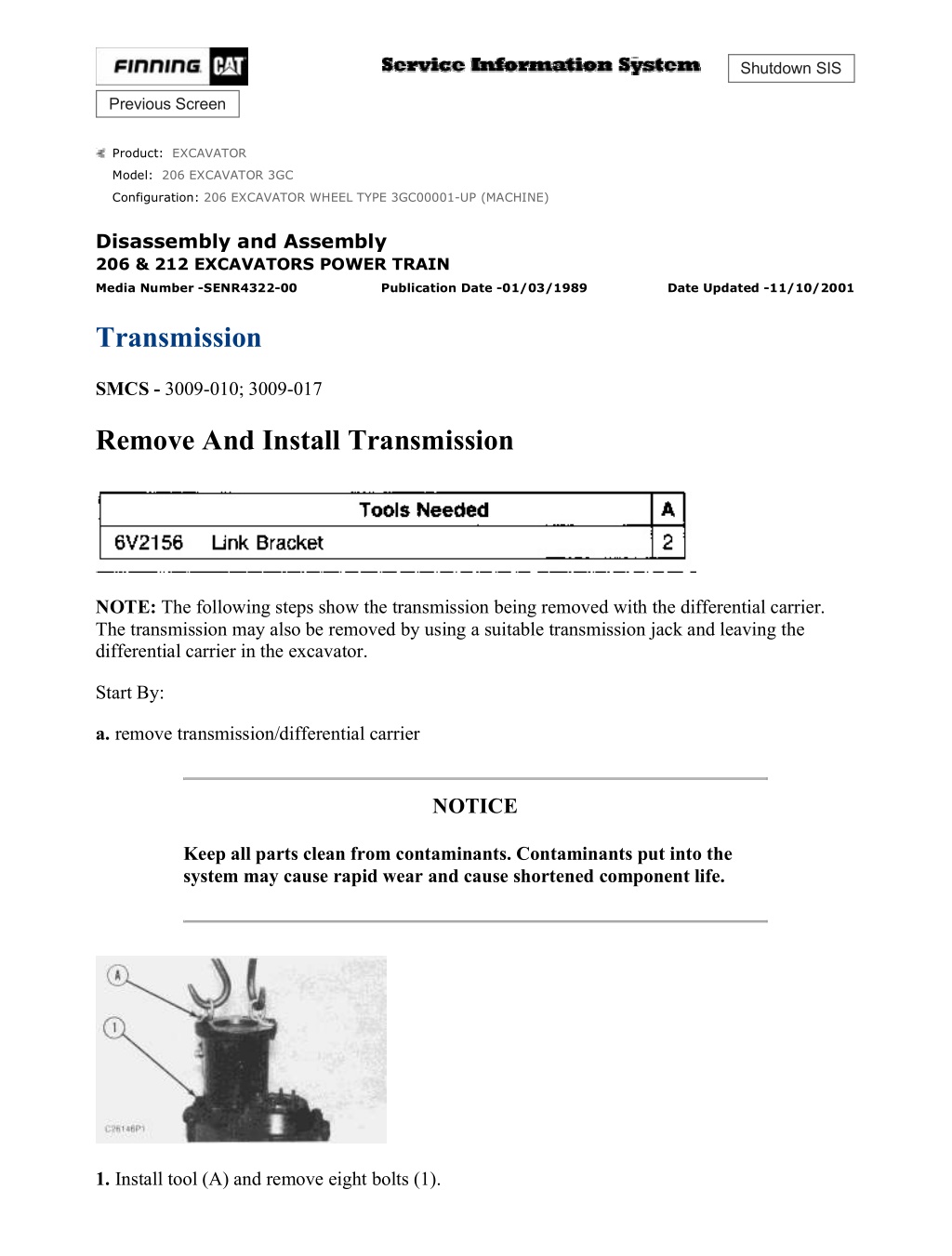
206 EXCAVATOR WHEEL TYPE 3GC00001-UP (MACHINE)(HMBP1480 - 04) - ... 1/14 Shutdown SIS Previous Screen Product: EXCAVATOR Model: 206 EXCAVATOR 3GC Configuration: 206 EXCAVATOR WHEEL TYPE 3GC00001-UP (MACHINE) Disassembly and Assembly 206 & 212 EXCAVATORS POWER TRAIN Media Number -SENR4322-00 Publication Date -01/03/1989 Date Updated -11/10/2001 Transmission SMCS - 3009-010; 3009-017 Remove And Install Transmission NOTE: The following steps show the transmission being removed with the differential carrier. The transmission may also be removed by using a suitable transmission jack and leaving the differential carrier in the excavator. Start By: a. remove transmission/differential carrier NOTICE Keep all parts clean from contaminants. Contaminants put into the system may cause rapid wear and cause shortened component life. 1. Install tool (A) and remove eight bolts (1). https://127.0.0.1/sisweb/sisweb/techdoc/techdoc_print_page.jsp?returnurl=/sis... 2021/10/17
206 EXCAVATOR WHEEL TYPE 3GC00001-UP (MACHINE)(HMBP1480 - 04) - ... 2/14 2. Lift transmission from transmission/differential carrier assembly. The weight of the transmission is 30 kg (65 lb). NOTE: The following steps are to install the transmission. 3. Position transmission into dropbox of transmission/differential carrier assembly and secure with eight bolts (1). 4. Remove tool (A). End By: a. install transmission/differential carrier Disassemble And Assemble Transmission Start By: a. remove transmission NOTICE https://127.0.0.1/sisweb/sisweb/techdoc/techdoc_print_page.jsp?returnurl=/sis... 2021/10/17
206 EXCAVATOR WHEEL TYPE 3GC00001-UP (MACHINE)(HMBP1480 - 04) - ... 3/14 Keep all parts clean from contaminants. Contaminants put into the system may cause rapid wear and cause shortened component life. 1. Use tool (A) and two blocks (X) to remove clutch assembly (1) from transmission housing (2). 2. Remove three seals (4) and one O-ring seal (3) from shaft (5). 3. Use tool (B) and remove retaining ring (6). Remove gear (7) and shaft (5). NOTE: On clutch pack removal, maintain the correct sequence of disks and plates as there are different thicknesses of disks and plates. 4. Remove retaining ring (8) and clutch pack (9). https://127.0.0.1/sisweb/sisweb/techdoc/techdoc_print_page.jsp?returnurl=/sis... 2021/10/17
https://www.ebooklibonline.com Hello dear friend! Thank you very much for reading. Enter the link into your browser. The full manual is available for immediate download. https://www.ebooklibonline.com
206 EXCAVATOR WHEEL TYPE 3GC00001-UP (MACHINE)(HMBP1480 - 04) - ... 4/14 5. Use a shop press and tool (C) to compress spring washer (10) and remove retaining ring (11). Release compression and remove plate (12) and spring washer (10). 6. Remove flange (13) from gear (14) by means of compressed air in port (Y). 7. Remove retaining ring (15), washer (16) and O-ring seal (17). Remove gear (14) from guide (19). 8. With retaining ring pliers* remove retaining ring (20) and gear (18) from guide (19). NOTE: * Contact Caterpillar Service Technology Group for information regarding the type of retaining ring pliers to use. https://127.0.0.1/sisweb/sisweb/techdoc/techdoc_print_page.jsp?returnurl=/sis... 2021/10/17
206 EXCAVATOR WHEEL TYPE 3GC00001-UP (MACHINE)(HMBP1480 - 04) - ... 5/14 9. Remove retaining ring (22) and seal (23) from guide (19). Remove three seals (24) and two O- ring seals (25). 10. Remove retaining ring (26), seal (27) and two bearings (28) from gear (18). 11. From gear (18), remove ring (29), retaining ring (30) and washer (31). 12. Using tool (D), remove bearing (32), washer (33) and retaining ring (20) from gear (18). https://127.0.0.1/sisweb/sisweb/techdoc/techdoc_print_page.jsp?returnurl=/sis... 2021/10/17
206 EXCAVATOR WHEEL TYPE 3GC00001-UP (MACHINE)(HMBP1480 - 04) - ... 6/14 13. Remove retaining ring (34) and clutch pack disks and plates (35) from transmission (2). 14. Using a shop press and tool (C), compress spring seat (37) and remove retaining ring (36). Release press and remove seat (37) and spring (38) from transmission housing (2). 15. Remove retaining ring (39) and gear (40). https://127.0.0.1/sisweb/sisweb/techdoc/techdoc_print_page.jsp?returnurl=/sis... 2021/10/17
206 EXCAVATOR WHEEL TYPE 3GC00001-UP (MACHINE)(HMBP1480 - 04) - ... 7/14 16. Remove washer (41) from gear (40). 17. Turn gear (40) over and apply air pressure to port (Z) to remove flange (42). 18. Remove five bolts (43). Under each bolt (43) is a special seal washer which must be replaced at assembly with a new seal washer. Using a plastic mallet from opposite end, drive shaft assembly (44) out of transmission housing (2). 19. Remove O-ring seal (45) from transmission housing (2). 20. From shaft assembly (44), remove rotor (46) and pin (47). https://127.0.0.1/sisweb/sisweb/techdoc/techdoc_print_page.jsp?returnurl=/sis... 2021/10/17
206 EXCAVATOR WHEEL TYPE 3GC00001-UP (MACHINE)(HMBP1480 - 04) - ... 8/14 21. Remove O-ring seal (49), ring (48) and two rings (50) from shaft assembly (44). 22. Attach tooling (F) to needle bearing (58) inside shaft (44). Attach tooling (G) to tooling (F) and use two spacer blocks (X) to pull two needle bearings out of shaft (44). 23. Turn shaft assembly (44) over and remove retaining ring (51) and seal (52). Seal (52) will be destroyed and must be replaced with a new seal at assembly. 24. Remove retaining ring (53), spacer (54) and thrust washer (55) from shaft (44). https://127.0.0.1/sisweb/sisweb/techdoc/techdoc_print_page.jsp?returnurl=/sis... 2021/10/17
206 EXCAVATOR WHEEL TYPE 3GC00001-UP (MACHINE)(HMBP1480 - 04) - ... 9/14 25. Remove retaining ring (56) and use tool (D) and tool (E) to remove bearing (57) from shaft (44). NOTE: The following steps are to assemble the transmission 26. Heat bearing (57) to 135 C (275 F), and install on shaft (44). Install retaining ring (56). 27. Insert shaft assembly (44) into thrust washer (55). Install spacer (54) and retaining ring (53). 28. Install seal (52) into shaft assembly (44) with tooling (H) and secure with retaining ring (51). 29. Install needle bearing (58) into shaft assembly (44). Install two rings (50), ring (48) and O-ring seal (49) on shaft assembly (44). 30. Install pin (47). Coat rotor (46) with 5P0960 Grease and install on shaft assembly (44). 31. Coat O-ring seal (45) with lubricant and install in transmission housing (2). 32. Lubricate rings (50) and insert shaft assembly (44) into transmission housing (2). Install five bolts (43) with new seals on each bolt. torque to 10 N m (7.4 lb ft). 33. Place new seal on flange (42) and install flange into gear (40). Place spring (38) and spring seat (37) into gear (40). Compress with tool (C) and install retaining ring (36). https://127.0.0.1/sisweb/sisweb/techdoc/techdoc_print_page.jsp?returnurl=/sis... 2021/10/17
206 EXCAVATOR WHEEL TYPE 3GC00001-UP (MACHINE)(HMBP1480 - 04) ... 10/14 34. Install clutch pack (35), beginning with thick outer plate (59) and ending with pressure plate (60), and install retaining ring (34). 35. Compress clutch pack (35) with a pressure of 200 N m (148 lb ft), and measure depth A of pressure plate (60) with tool (H). 36. Remove clutch pack assembly (35) from press and apply pressure to pressure plate (60) to push plate against retaining ring (34) and measure depth B with tool (H). The difference in value between measurement A and B should be 2.2mm 1.5mm. If value is not within specification, adjust with different value retaining ring (34). See Parts Book for 206 or 212 Excavators. 37. Install washer (41) and retaining ring (39). https://127.0.0.1/sisweb/sisweb/techdoc/techdoc_print_page.jsp?returnurl=/sis... 2021/10/17
206 EXCAVATOR WHEEL TYPE 3GC00001-UP (MACHINE)(HMBP1480 - 04) ... 11/14 38. In guide (19) use tool (J) and install new seal (23). Install retaining ring (22), new O-ring seals (25) and three seals (24). 39. Place bearing (32) into bore of guide (19) and install retaining ring (20). Measure distance between bearing and retaining ring with a feeler gauge, and select from Parts Book for 206 or 212 Excavators the correct washer (33) to eliminate any bearing end play. After correct washer has been selected, remove retaining ring (20) and bearing (32) from guide (19). 40. Install retaining ring (20) and washer (33) on gear (18). 41. Press bearing (32) on gear (18) firmly against shoulder. Install retaining ring (30). Measure distance between bearing (32) and retaining ring (30). Select correct washer (31) from 206 or 212 Excavators Parts Book to remove any bearing play and remove retaining ring (30). https://127.0.0.1/sisweb/sisweb/techdoc/techdoc_print_page.jsp?returnurl=/sis... 2021/10/17
206 EXCAVATOR WHEEL TYPE 3GC00001-UP (MACHINE)(HMBP1480 - 04) ... 12/14 42. Install washer (31) and retaining ring (30). 43. Install ring (29) and gear (18). 44. Install two roller bearings (28), seal (27) and retaining ring (26) in gear (18). 45. Install gear assembly (18) into guide (19) and using special retaining ring pliers* install retaining ring (20) into guide (19). NOTE: * Contact Caterpillar Service Technology Group for information regarding the type of retaining ring pliers to use. https://127.0.0.1/sisweb/sisweb/techdoc/techdoc_print_page.jsp?returnurl=/sis... 2021/10/17
206 EXCAVATOR WHEEL TYPE 3GC00001-UP (MACHINE)(HMBP1480 - 04) ... 13/14 46. Install gear (14) on guide (19). Install O-ring seal (17), washer (16) and retaining ring (15). 47. Replace O-ring seal (61) in flange (13). Install flange (13) into gear (14). 48. Install spring washer (10) in gear (14). With a shop press and tool (C), compress spring washer (10) and install plate (12) and retaining ring (11). 49. Install clutch pack (9) starting with the thick outer plate. Alternate with disks and plates. Three of the plates are available in various thicknesses. These are used to adjust proper clutch play. See the 206 or 212 Excavators Parts Book for these plates. End by installing the last plate and the retaining ring (8). Check clutch play by measuring distance between last plate and retaining ring (8). The clutch play should be 1.3mm +1.5, - 0.0mm. 50. Install O-ring seal (3) and three seals (4) on shaft (5). Install shaft (5) into clutch assembly. 51. Install tool (L) and align clutch plates with tool (K). https://127.0.0.1/sisweb/sisweb/techdoc/techdoc_print_page.jsp?returnurl=/sis... 2021/10/17
206 EXCAVATOR WHEEL TYPE 3GC00001-UP (MACHINE)(HMBP1480 - 04) ... 14/14 52. Align clutch assembly (1) with tool (M) and apply air pressure in port (Y) to hold clutch pack in position. 53. Pressurize transmission housing (2) with air to hold clutch assembly in position and carefully lower clutch assembly (1) into transmission housing clutch assembly. Care should be taken to align port (y) in clutch assembly (1) in proper position in transmission housing (2). End By: a. install transmission NOTICE Perform Scheduled Oil Sampling on oil wetted compartments after performing service work to check for contaminants left in the compartment following repair. Contaminants put into the system may cause rapid wear and shortened component life. Copyright 1993 - 2021 Caterpillar Inc. Sun Oct 17 10:24:20 UTC+0800 2021 All Rights Reserved. Private Network For SIS Licensees. https://127.0.0.1/sisweb/sisweb/techdoc/techdoc_print_page.jsp?returnurl=/sis... 2021/10/17
206 EXCAVATOR WHEEL TYPE 3GC00001-UP (MACHINE)(HMBP1480 - 04) - ... 1/1 Shutdown SIS Previous Screen Product: EXCAVATOR Model: 206 EXCAVATOR 3GC Configuration: 206 EXCAVATOR WHEEL TYPE 3GC00001-UP (MACHINE) Disassembly and Assembly 206 & 212 EXCAVATORS POWER TRAIN Media Number -SENR4322-00 Publication Date -01/03/1989 Date Updated -11/10/2001 Axle Housing (Rear) SMCS - 4313-010 Remove And Install Axle Housing (Rear) Start By: a. remove rear drive shaft b. remove rear wheels and tires 1. Install suitable transmission jack. Remove two hydraulic lines (1) and eight bolts (2). Lower the rear axle housing and remove it from under machine. NOTE: The following step is to install the rear axle housing. 2. Position rear axle housing under excavator, raise with suitable transmission jack and install eight bolts (2) and two hydraulic lines (1). End By: a. install rear wheels and tires b. install rear drive shaft Copyright 1993 - 2021 Caterpillar Inc. Sun Oct 17 10:25:16 UTC+0800 2021 All Rights Reserved. Private Network For SIS Licensees. https://127.0.0.1/sisweb/sisweb/techdoc/techdoc_print_page.jsp?returnurl=/sis... 2021/10/17
206 EXCAVATOR WHEEL TYPE 3GC00001-UP (MACHINE)(HMBP1480 - 04) - ... 1/2 Shutdown SIS Previous Screen Product: EXCAVATOR Model: 206 EXCAVATOR 3GC Configuration: 206 EXCAVATOR WHEEL TYPE 3GC00001-UP (MACHINE) Disassembly and Assembly 206 & 212 EXCAVATORS POWER TRAIN Media Number -SENR4322-00 Publication Date -01/03/1989 Date Updated -11/10/2001 Axle Housing (Front) SMCS - 4313-010 Remove And Install Axle Housing (Front) Start By: a. remove wheels and tires (front only) b. remove axles (front) c. remove drive shaft (front) 1. Use suitable floor jack and wood block to support the front axle housing. 2. Remove pin (1) and lower front axle housing. The weight of the front axle housing is 264 kg (580 lb). 3. Inspect and replace two bushings (2) if necessary. https://127.0.0.1/sisweb/sisweb/techdoc/techdoc_print_page.jsp?returnurl=/sis... 2021/10/17
206 EXCAVATOR WHEEL TYPE 3GC00001-UP (MACHINE)(HMBP1480 - 04) - ... 2/2 NOTE: The following steps are to install the front axle housing. 4. Position front axle housing on suitable floor jack. 5. Raise front axle housing into position and install pin (1). Copyright 1993 - 2021 Caterpillar Inc. Sun Oct 17 10:26:12 UTC+0800 2021 All Rights Reserved. Private Network For SIS Licensees. https://127.0.0.1/sisweb/sisweb/techdoc/techdoc_print_page.jsp?returnurl=/sis... 2021/10/17
206 EXCAVATOR WHEEL TYPE 3GC00001-UP (MACHINE)(HMBP1480 - 04) - ... 1/10 Shutdown SIS Previous Screen Product: EXCAVATOR Model: 206 EXCAVATOR 3GC Configuration: 206 EXCAVATOR WHEEL TYPE 3GC00001-UP (MACHINE) Disassembly and Assembly 206 & 212 EXCAVATORS POWER TRAIN Media Number -SENR4322-00 Publication Date -01/03/1989 Date Updated -11/10/2001 Differential (Front) SMCS - 3258-010 Remove And Install Differential (Front) Start By: a. remove axle housing (front) NOTICE Keep all parts clean from contaminants. Contaminants put into the system may cause rapid wear and shortened component life. 1. Attach tooling (A) to differential housing (1). 2. Remove twelve bolts (2) and remove differential housing. The weight of the differential housing is 127 kg (280 lb). https://127.0.0.1/sisweb/sisweb/techdoc/techdoc_print_page.jsp?returnurl=/sis... 2021/10/17
206 EXCAVATOR WHEEL TYPE 3GC00001-UP (MACHINE)(HMBP1480 - 04) - ... 2/10 NOTE: The following steps are to install the differential (front). NOTE: Make sure ring gear (3) is in proper position to axle housing. If ring gear is installed on the wrong side the wheels will turn in the opposite direction. 3. Install guide bolt (4). Attach tooling (A) to differential housing and lower housing into front axle housing. 4. Install twelve bolts (2). Disassemble And Assemble Differential (Front) Start By: a. remove front differential NOTICE Keep all parts clean from contaminants. Contaminants put into the system may cause rapid wear and shortened component life. https://127.0.0.1/sisweb/sisweb/techdoc/techdoc_print_page.jsp?returnurl=/sis... 2021/10/17
206 EXCAVATOR WHEEL TYPE 3GC00001-UP (MACHINE)(HMBP1480 - 04) - ... 3/10 1. Drive two roll pins (1) up so that the two castle nuts (2) can be removed. 2. Remove four bolts (3), two bearing caps (4), two castle nuts (2) and two cup bearings (5). 3. Remove ring gear shaft assembly (6). 4. Remove eight bolts (7) and four bolts (8) to remove ring gear (9). 5. Mark top and bottom housings and remove top housing (10) from ring gear shaft assembly (6). 6. From bottom housing (11), remove thrust washer (12) and gear (13). https://127.0.0.1/sisweb/sisweb/techdoc/techdoc_print_page.jsp?returnurl=/sis... 2021/10/17
206 EXCAVATOR WHEEL TYPE 3GC00001-UP (MACHINE)(HMBP1480 - 04) - ... 4/10 7. From bottom housing (11), remove spider gear set (14), gear (15) and thrust washer (16). 8. Place top housing (10) in press. Install tooling (A) and remove cone bearing (17). 9. Place bottom housing (11) in press. Install tooling (A) and remove cone bearing (18). 10. From housing (19) remove nut (20), washer (21) and flange (22). https://127.0.0.1/sisweb/sisweb/techdoc/techdoc_print_page.jsp?returnurl=/sis... 2021/10/17
206 EXCAVATOR WHEEL TYPE 3GC00001-UP (MACHINE)(HMBP1480 - 04) - ... 5/10 11. Place housing (19) in press and remove pinion shaft assembly (23). 12. From housing (19) remove seal (24) and cup and cone bearings (25). 13. Turn housing (19) over and remove cup bearing (26) and shim (27) located behind cup bearing (26). 14. From pinion shaft assembly (23) remove bushing (29). Place pinion shaft in press and use tool (A) to remove bearing (28). NOTE: The following steps are to assemble the front differential. https://127.0.0.1/sisweb/sisweb/techdoc/techdoc_print_page.jsp?returnurl=/sis... 2021/10/17
206 EXCAVATOR WHEEL TYPE 3GC00001-UP (MACHINE)(HMBP1480 - 04) - ... 6/10 15. To determine proper shim (27) for pinion gear tooth contact, install tools (B) and (C) and bearing caps (4) with bolts (3). Measure distance with tool (D) from top of tool (C) to face of bearing bore in housing (18). Dimension = Z. Subtract 1/2 of the diameter of tool (C) from dimension Z and determine dimension Y. 16. Place cup bearing (26) on cone bearing (28) and with tool (D) measure thickness. Dimension = X. 17. Read dimension W off the end of the pinion gear (23) and calculate Y - X - W = proper shim (27) thickness. Select proper shim from the 206 or 212 Excavators Parts Book. 18. Freeze shim (27) and cup bearing (26) and install into housing (19). 19. Heat bearing (28) to 135 (275 F), and install on pinion gear shaft (23). Install bushing (29) on pinion gear shaft (23). 20. Turn housing (19) over and install cup and cone bearing (25) and seal (24). https://127.0.0.1/sisweb/sisweb/techdoc/techdoc_print_page.jsp?returnurl=/sis... 2021/10/17
206 EXCAVATOR WHEEL TYPE 3GC00001-UP (MACHINE)(HMBP1480 - 04) - ... 7/10 21. Using press install pinion shaft assembly (23) into housing (19). 22. Install flange (22), washer (21) and nut (20). See Specification Manual for the proper torque for nut (20). 23. Press bearing (18) onto housing (11). 24. Press bearing (17) onto housing (10). 25. Install thrust washer (16) and gear (15) into housing (11). 26. Install four washers and four gears as shown onto spider assembly (14) and install spider assembly (14) into housing (11). 27. Place gear (13) and thrust washer (12) on spider assembly (14) in housing (11). NOTE: The thrust washer tabs on washers (16) and (12) must be in the slots in the housings (11) and (10). 28. Place housing (10) on housing (11) lining up reference mark mentioned in Step (5). 29. Heat gear (9) to 135 (275 F), and install on ring gear shaft assembly (6) so that roll pin holes and bolt holes line up. 30. Install four bolts (8) and eight bolts (7). Apply 9S3263 Thread Lock to bolts. 31. Install ring gear assembly (6), with two cup bearings (5), into differential carrier. Install two nuts (2) to hold bearings (5) in place. 32. Install two bearing caps (4) with four bolts (3). Make sure roll pins (1) are driven up to allow adjusting of nuts (2) to set backlash. Hand tighten bolts (3). https://127.0.0.1/sisweb/sisweb/techdoc/techdoc_print_page.jsp?returnurl=/sis... 2021/10/17
206 EXCAVATOR WHEEL TYPE 3GC00001-UP (MACHINE)(HMBP1480 - 04) - ... 8/10 33. Install tool (E) and adjust nut (2) on bevel gear side to obtain a backlash of 0.18 - 0.3mm. 34. Screw in nut (2) on opposite end of bevel gear to remove all slack in bearing and then turn nut two more notches. Check backlash and correct if necessary. 35. Tighten bolts (3) to 210 N m (155 lb ft). Check ring gear backlash to make sure it has not changed. If the back lash is out of tolerance, repeat Steps 32, 33, 34 and 35 again. 36. After the backlash and differential bearing preload have been made, check tooth contact between the bevel gear and the pinion as follows: a. Put a small amount of Prussian Blue, red lead or paint on the bevel gear teeth. Turn the pinion and inspect the marks made on the bevel gear teeth. Correct Tooth Contact (No Load) Correct Tooth Contact (With Load) b. With no load, correct tooth contact will be as shown. The area of contact starts near the toe of the gear and moves approximately half way up the length of the tooth. With this setting, the tooth contact will be as shown when a load is put on the gear. https://127.0.0.1/sisweb/sisweb/techdoc/techdoc_print_page.jsp?returnurl=/sis... 2021/10/17
206 EXCAVATOR WHEEL TYPE 3GC00001-UP (MACHINE)(HMBP1480 - 04) - ... 9/10 Short Toe Contact c. If the pinion is too far away from the bevel gear, short toe contact will be the result. The teeth on the pinion will make contact with the surfaces of the teeth that make a curve toward the outside (convex surfaces) at the toe ends, and the surfaces of the teeth that make a curve toward the inside (concave surfaces) and the heel ends. Short toe contact must be corrected by an increase to the thickness of shim between the pinion bearing cage and the carrier. This will move the pinion in the direction of the arrow. Check backlash and tooth contact again. Move the bevel gear in the direction of the arrow if needed to keep the correct backlash. Short Heel Contact d. If the pinion is too near the center of the bevel gear, short heel contact will be the result. The teeth on the pinion will make contact with the concave surfaces of the teeth at the toe ends, and the convex surfaces of the teeth at the heel ends. Short heel contact must be corrected by a decrease in the thickness of shim between the pinion bearing cage and the carrier. This will move the pinion in the direction of the arrow. Check the backlash and tooth contact again. Move the bevel gear in the direction of the arrow if needed to keep the correct backlash. NOTE: It is possible that several adjustments of both the pinion and the bevel gear will have to be made before the backlash and tooth contact are correct. Always remember that any change to the backlash will also change the tooth contact. The backlash must be correct before the tooth contact is checked. e. Remove the Prussian Blue, red lead or paint from the gears after the correct tooth contact is made. 37. Drive roll pins (1) down to lock nuts (2). End By: a. install differential (front) NOTICE https://127.0.0.1/sisweb/sisweb/techdoc/techdoc_print_page.jsp?returnurl=/sis... 2021/10/17
Suggest: If the above button click is invalid. Please download this document first, and then click the above link to download the complete manual. Thank you so much for reading
206 EXCAVATOR WHEEL TYPE 3GC00001-UP (MACHINE)(HMBP1480 - 04) ... 10/10 Perform Scheduled Oil Sampling on oil wetted compartments after performing service work to check for contaminants left in the compartment following repair. Contaminants put into the system may cause rapid wear and shortened component life. Copyright 1993 - 2021 Caterpillar Inc. Sun Oct 17 10:27:07 UTC+0800 2021 All Rights Reserved. Private Network For SIS Licensees. https://127.0.0.1/sisweb/sisweb/techdoc/techdoc_print_page.jsp?returnurl=/sis... 2021/10/17
https://www.ebooklibonline.com Hello dear friend! Thank you very much for reading. Enter the link into your browser. The full manual is available for immediate download. https://www.ebooklibonline.com
(HMBP1480 -")
(HMBP1480 -")
(HMBP1480 -")

(HMBP1480 -")
(HMBP1480 -")
(HMBP1480 -")
(HMBP1480 -")
(HMBP1480 -")
(HMBP1480 -")
(HMBP1480 -")
(HMBP1480 -")
(HMBP1480 -")
(HMBP1480 -")
(HMBP1480 -")
(HMBP1480 -")
(HMBP1480 -")
(HMBP1480 -")
(HMBP1480 -")
(HMBP1480 -")
(HMBP1480 -")
(HMBP1480 -")
(HMBP1480 -")
(HMBP1480 -")
(HMBP1480 -")
(HMBP1480 -")
(HMBP1480 -")

(HMBP1480 -")