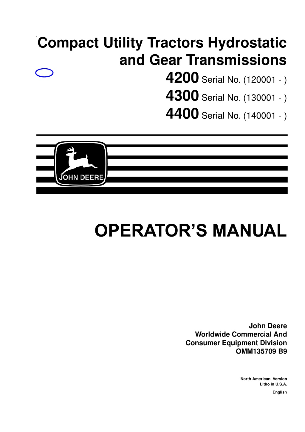
John Deere 4300 Compact Utility Tractors With Hydrostatic Transmission and Gear Transmissions Operator’s Manual Instant Download (Publication No.OMM135709)
Please open the website below to get the complete manualnn// n
Download Presentation

Please find below an Image/Link to download the presentation.
The content on the website is provided AS IS for your information and personal use only. It may not be sold, licensed, or shared on other websites without obtaining consent from the author. Download presentation by click this link. If you encounter any issues during the download, it is possible that the publisher has removed the file from their server.
E N D
Presentation Transcript
B9Compact Utility Tractors Hydrostatic and Gear Transmissions 4200 Serial No. (120001 - ) 4300 Serial No. (130001 - ) 4400 Serial No. (140001 - ) OPERATOR S MANUAL John Deere Worldwide Commercial And Consumer Equipment Division OMM135709 B9 North American Version Litho in U.S.A. English
INTRODUCTION THANK YOU for purchasing a John Deere product. Read this manual and your attachment manuals thoroughly. Failure to do so could result in personal injury or equipment damage. WARNING: The Engine Exhaust from this product contains chemicals known to the State of California to cause cancer, birth defects or other reproductive harm. CALIFORNIA Proposition 65 Warning This manual should be considered a permanent part of your machine and should remain with the machine when you sell it. Measurements in this manual are metric units and their U.S. customary equivalents. RIGHT-HAND and LEFT- HAND sides are determined by facing in the direction the machine will travel when going forward. When you see a broken line arrow (----->), it indicates the part it is pointing to is hidden. Record identification numbers below. Be sure to record all the numbers to help in tracing the machine if it is stolen. You also need to give these numbers to your dealer when you order parts. DATE OF PURCHASE: ________________________________ DEALER NAME: ________________________________ DEALER PHONE: ________________________________ PRODUCT IDENTIFICATION NUMBER (A): __ __ __ __ __ __ __ __ __ __ __ __ __ ENGINE SERIAL NUMBER (B): __ __ __ __ __ __ __ __ __ __ __ __ __ B A Introduction
TABLE OF CONTENTS Safety Signs . . . . . . . . . . . . . . . . . . . . . . . . . . . . . . . . . . . . . . . . . . . . . . . . . . . . . . . . . . . . . . . . . . . . . 1 Controls . . . . . . . . . . . . . . . . . . . . . . . . . . . . . . . . . . . . . . . . . . . . . . . . . . . . . . . . . . . . . . . . . . . . . . . . 4 Operating (Gear Models) . . . . . . . . . . . . . . . . . . . . . . . . . . . . . . . . . . . . . . . . . . . . . . . . . . . . . . . . . . . 8 Operating (Hydrostatic Models) . . . . . . . . . . . . . . . . . . . . . . . . . . . . . . . . . . . . . . . . . . . . . . . . . . . . . 53 Replacement Parts. . . . . . . . . . . . . . . . . . . . . . . . . . . . . . . . . . . . . . . . . . . . . . . . . . . . . . . . . . . . . . . 95 Service Machine Safely . . . . . . . . . . . . . . . . . . . . . . . . . . . . . . . . . . . . . . . . . . . . . . . . . . . . . . . . . . . 96 Service Interval Chart. . . . . . . . . . . . . . . . . . . . . . . . . . . . . . . . . . . . . . . . . . . . . . . . . . . . . . . . . . . . . 98 Service Engine . . . . . . . . . . . . . . . . . . . . . . . . . . . . . . . . . . . . . . . . . . . . . . . . . . . . . . . . . . . . . . . . . 102 Service Transmission . . . . . . . . . . . . . . . . . . . . . . . . . . . . . . . . . . . . . . . . . . . . . . . . . . . . . . . . . . . . 123 Service Electrical . . . . . . . . . . . . . . . . . . . . . . . . . . . . . . . . . . . . . . . . . . . . . . . . . . . . . . . . . . . . . . . 128 Service Miscellaneous . . . . . . . . . . . . . . . . . . . . . . . . . . . . . . . . . . . . . . . . . . . . . . . . . . . . . . . . . . . 136 Troubleshooting . . . . . . . . . . . . . . . . . . . . . . . . . . . . . . . . . . . . . . . . . . . . . . . . . . . . . . . . . . . . . . . . 151 Storing Machine . . . . . . . . . . . . . . . . . . . . . . . . . . . . . . . . . . . . . . . . . . . . . . . . . . . . . . . . . . . . . . . . 157 Assembly . . . . . . . . . . . . . . . . . . . . . . . . . . . . . . . . . . . . . . . . . . . . . . . . . . . . . . . . . . . . . . . . . . . . . 159 Specifications . . . . . . . . . . . . . . . . . . . . . . . . . . . . . . . . . . . . . . . . . . . . . . . . . . . . . . . . . . . . . . . . . . 162 Warranty . . . . . . . . . . . . . . . . . . . . . . . . . . . . . . . . . . . . . . . . . . . . . . . . . . . . . . . . . . . . . . . . . . . . . . 176 Index. . . . . . . . . . . . . . . . . . . . . . . . . . . . . . . . . . . . . . . . . . . . . . . . . . . . . . . . . . . . . . . . . . . . . . . . . 180 John Deere Service Literature . . . . . . . . . . . . . . . . . . . . . . . . . . . . . . . . . . . . . . . . . . . . . . . . . . . . . 187 All information, illustrations and specifications in this manual are based on the latest information at the time of publication. The right is reserved to make changes at any time without notice. COPYRIGHT 1999 Deere & Co. John Deere Worldwide Commercial and Consumer Equipment Division Horicon, WI All rights reserved Previous versions 1998 OMM135709 B9 Table of Contents
https://www.ebooklibonline.com Hello dear friend! Thank you very much for reading. Enter the link into your browser. The full manual is available for immediate download. https://www.ebooklibonline.com
SAFETY SIGNS Safety-Alert Symbol Read and recognize safety information. Be alert to the potential for personal injury when you see this safety- alert symbol. On your machine safety labels, the words DANGER, WARNING, and CAUTION are used with this safety- alert symbol. DANGER identifies the most serious hazards. In this manual, the word CAUTION and this symbol call attention to safety messages. Machine Safety Labels CAUTION (A) A B 1. Read Operator s Manual before operating this tractor. 2. Keep all shields in place. 3. Hitch towed loads only to drawbar to avoid rearward upset. 4. Make certain everyone is clear of machine before starting engine or operation. 5. Keep all riders off tractor and equipment. 6. Keep hands, feet and clothing away from power- driven parts. 7. Reduce speed when turning or applying individual brakes or operating around hazards on rough ground or steep slopes. 8. Couple brake pedals together for road travel. 9. Use flashing warning lights on highway unless prohibited by law. 10.Stop engine, lower implement to ground and shift to PARK or set brake(s) securely before dismounting. 11.Wait for all movement to stop before servicing machinery. 12.Remove key if leaving tractor unattended. M63797 WARNING (B) AVOID CRUSHING Do not jump if machine tips USE SEAT BELT Safety Signs - Page 1
SAFETY SIGNS WARNING AVOID CRUSHING: Keep Rollover Protective Structure fully extended. Do not jump if machine tips. Use seat belt. When structure must be down; DO NOT use seat belt. Drive with extra care. M64049 CAUTION: DO NOT touch engine muffler, it may be hot. M94385 DANGER/POISON SHIELD EYES EXPLOSIVE BATTERY GASES CAN CAUSE BLINDNESS OR INJURY NO SPARKS FLAMES SMOKING SULFURIC ACID CAN CAUSE BLINDNESS OR SEVERE BURNS FLUSH EYES IMMEDIATELY WITH WATER GET MEDICAL HELP FAST KEEP OUT OF THE REACH OF CHILDREN. DO NOT TIP. KEEP VENT CAPS TIGHT AND LEVEL. M94377 Safety Signs - Page 2
SAFETY SIGNS WARNING AVOID INJURY FROM PTO Keep all shields in place. Keep hands, feet and clothing away. Operate only with 540 RPM. M63702 DANGER Start only from seat in park or neutral. Starting in gear kills. M63152 Safety Signs - Page 3
CONTROLS Operator Station Controls Collar Shift and SyncReverser Models A - Clutch Pedal B - Steering Column Tilt Lock Lever C - Fuse Panel D - Foot Throttle E - Turn-Brake, Left Pedal F - Turn Brake, Right Pedal G - Turn Brake Lock Lever H - Selective Control Valve (SCV) Control Lever I - Mid-PTO Engagement Lever J - PTO Engagement Lever K - Rockshaft Position Control Lever L - Seat Belt M - Seat Belt Latch N - Range Shift Lever O - Gear Shift Lever P - Park Brake Lever Q - Seat Height Adjustment Knob R - Seat Spring Tension Knob S - Seat Adjustment Lever T - Rockshaft Speed-of-Drop Control Knob U - Differential Lock Lever V - SCV Control Lever Lock G A B C F E D H O P I N K J M L M63789 R Q S H T U V M63790 Controls - Page 4
CONTROLS Operator Station Controls Hydrostatic Models A - Master Brake B - Forward Hydrostatic Pedal C - Reverse Hydrostatic Pedal D - Turn-Brake, Left Pedal E - Turn Brake, Right Pedal F - Park Brake Lever G - Range Shift Lever H - Seat Belt Latch I - Selective Control Valve (SCV) Control Lever J - Mid-PTO Engagement Lever K - PTO Engagement Lever L - Rockshaft Height Control Lever M - Seat Belt A B C M63792 E D M63793 I F J G K H M L M63794 M63795 Controls - Page 5
CONTROLS Instrument Panel A - Fuel Gauge B - Tachometer C - Engine Coolant Temperature Gauge D - Reverser Lever E - Turn Signal Control Lever F - Light - PTO Engage G - Light - Cruise Control (Hydrostatic Only) H - Light - Cold Start Circuit I - Hourmeter J - Light - Battery Charging K - Light - Park Brake L - Light - Engine Oil Pressure M - Hand Throttle N - Key Switch O - Light Switch P - Left Turn Signal Indicator Lamp Q - Right Turn Signal Indicator Lamp B C A I J K L F G H M O E D N M63788 A P B Q C F G H I J K L Controls - Page 6
CONTROLS Hood Controls A - Hood Release B - Hood Support B A M63625 Three-Point Hitch A A - Center Link Storage Hook B - Lift Arms C - Center Link D - Lift Link - Solid E - Lift Link - Adjustable F - Sway Links - Adjustable G - Draft Links B B F C D E F G G M63791 Controls - Page 7
OPERATING (GEAR MODELS) Operate Safely Check brake action before you operate. Adjust or service brakes as necessary. Inspect machine before you operate. Be sure hardware is tight. Repair or replace damaged, badly worn, or missing parts. Be sure guards and shields are in good condition and fastened in place. Make any necessary adjustments before you operate. Clear work area of objects that might be thrown. Keep people and pets out of the work area. Stop machine if anyone enters the area. If you hit an object, stop and inspect the machine. Make repairs before you operate. Keep machine and attachments properly maintained and in good working order. DO NOT leave machine unattended when it is running. Only operate during daylight or with good artificial light. Be careful of traffic when operating near or crossing roadways. Do not wear radio or music headphones while operating the machine. Safe operation requires your full attention. Park Safely Stop machine on a level surface, not on a slope. Disengage PTO. Apply park brake. STOP engine. Remove key. Before you leave the operator s station, wait for engine and all moving parts to STOP. Use Seat Belt Properly Use a seat belt when you operate with a Roll-Over Protective Structure (ROPS) to minimize chance of injury from an accident, such as an overturn. Do not use a seat belt if operating without a ROPS or with optional folding ROPS in folded position. Operating (Gear Models) - Page 8
OPERATING (GEAR MODELS) Rotating Blades Are Dangerous - Protect Children And Prevent Accidents PROTECT CHILDREN: Never assume that children will remain where you last saw them. Children are attracted to mowing activity, stay alert to the presence of children. Keep children in the house when you are operating the machine. Turn machine off if a child enters the mowing area. Use extra care when you come to blind corners, shrubs, trees, or other objects that may block your vision. DO NOT let children or an untrained person operate the machine. DO NOT carry or let children ride on machine or any attachment. DO NOT tow children in a cart or trailer. HELP PREVENT SERIOUS OR FATAL ACCIDENTS: Be alert at all times, drive forward carefully. People ESPECIALLY CHILDREN can move quickly into the mowing area before you know it. Back carefully. Shut off PTO and look behind the machine carefully, ESPECIALLY FOR CHILDREN, before you back up. DO NOT mow in reverse unless it is absolutely necessary. Shut off PTO when you are not mowing. DO NOT operate machine if you are under the influence of drugs or alcohol. Operator Training Required Study operating section of this manual before operating the machine. Operate machine in an open, unobstructed area under the direction of an experienced operator. Learn the use of all controls. Operator experience is required to learn the moving, stopping, turning and other operating characteristics of the machine. Operating (Gear Models) - Page 9
OPERATING (GEAR MODELS) Avoid Tipping DO NOT drive where machine could slip or tip. Stay alert for holes and other hidden hazards in the terrain. Keep away from drop-offs. Slow down before you make a sharp turn or operate on a slope. When pulling loads or using heavy equipment, use only approved hitches, limit loads to those you can safely control, and use counterweights or wheel weights when required per this manual or your attachment manual. Drive up and down a hill - not across. Be careful when you change direction on a slope. DO NOT stop when going up hill or down hill. If machine stops going up hill, STOP PTO and back down slowly. DO NOT mow wet grass. Reduced traction could cause sliding. Check Wheel Bolts A serious accident could occur causing serious injury if wheel bolts are not tight. Check wheel bolt tightness at the following interval: After 3 hours of operation. After 10 hours of operation. Often during the first 100 hours of operation. Keep Riders Off Only allow the operator on the machine. Keep riders off. Riders on the machine or attachment may be struck by foreign objects or thrown off the machine causing serious injury. Riders obstruct the operator s view resulting in the machine being operated in an unsafe manner. Operating (Gear Models) - Page 10
OPERATING (GEAR MODELS) Wear Appropriate Clothing Wear close fitting clothing and safety equipment appropriate for the job. Loud noise can cause impairment or loss of hearing, wear a suitable protective device such as earplugs. Stay Clear of Rotating Drivelines Entanglement in rotating driveline can cause serious injury or death: Wear close fitting clothing. STOP the engine and be sure PTO driveline is stopped before getting near it. Transport Safely Use safety lights and devices. Slow moving machines when driven on public roads are hard to see, especially at night. Avoid personal injury or death resulting from a collision with a vehicle. Whenever driving on public roads, use flashing warning lights and turn signals according to local regulations. Extra flashing warning lights may need to be installed. Using Step The step (A) is located on the left side of the tractor. Grip the steering wheel and step up into the seat. A M93903A Operating (Gear Models) - Page 11
OPERATING (GEAR MODELS) Tow Loads Safely Stopping distance increases with speed and weight of towed loads, and on slopes. Towed loads with or without brakes that are too heavy for the tractor, or are towed too fast, can cause loss of control. Consider the total weight of the equipment and its load. Observe these recommended maximum road speeds, or local speed limits, which may be lower: If towed equipment does not have brakes, do not travel more than 32 km/h (20 mph), and do not tow loads more than 1.5 times the tractor weight. If towed equipment has brakes, do not travel more than 40 km/h (25 mph), and do not tow loads more than 4.5 times the tractor weight. Ensure the load does not exceed the recommended weight ratio. Add ballast to recommended maximum for tractor, lighten the load, or get a heavier towing unit. The tractor must be heavy and powerful enough with adequate braking power for the towed load. Use additional caution when towing loads under adverse surface conditions. whin turning, and on inclines. Using Tilt Steering Wheel 1. Pull up on tilt steering knob (A) to release the steering wheel (B). 2. Adjust the steering wheel to where you are comfortable. 3. Push down on knob (A) to lock in steering wheel position. B CAUTION: To avoid injury, be sure steering wheel is locked in position. A M63907 Operating (Gear Models) - Page 12
OPERATING (GEAR MODELS) Adjusting Operator Seat Before starting engine to drive tractor, adjust operator seat position, height and suspension to desirable positions. Select Seat Position 1. Move seat positioning lever (A) left. 2. Slide seat forward or rearward to desired position. 3. Release lever to lock seat in position. Make sure all controls can be easily accessed. Select Seat Height 1. Turn height adjustment knob (B) clockwise to raise operator seat. 2. Turn height adjustment knob (B) counterclockwise to lower operator seat. Adjust Ride Comfort Adjust seat spring tension knob (C) to the weight of the operator, so that the seat floats in the center of it s travel as the tractor traverses rough terrain. 1. With one hand hold height adjustment knob (B) in a fixed position. 2. Adjust seat suspension: Operator size indications are molded into the adjustment knob. Turn seat spring tension knob (C) to the right (clockwise) for a firmer ride. Turn seat spring tension knob (C) to the left (counterclockwise) for a softer ride. B A C M94388 Operating (Gear Models) - Page 13
OPERATING (GEAR MODELS) Using Seat Belt CAUTION: Use a seat belt when you operate with a Roll-Over Protective Structure (ROPS) to minimize chance of injury from an accident, such as an overturn. Do not use a seat belt if operating without a ROPS, or with optional folding ROPS in folded position. A Pull seat belt from retractor and across hips and waist, and insert buckle into latch on left side of seat. If seat belt stops short of being able to insert into latch, allow belt to pull back into retractor, and retry. Pull out from retractor with one continuous motion, and insert into latch. Listen for a click when inserted properly into latch. To release seat belt, press the red button (A). M94388 Using Ignition Switch IMPORTANT: When tractor is not be used or when tractor is being serviced, make sure key switch is in the OFF position and the key is removed. A- ACCESSORY Position - In this position power is supplied to accessories, but the engine will not be running. B - OFF Position - In this position the engine will not be running. C - ON Position - Move key from OFF to next position and the Engine Oil Pressure Light and Battery Charging Light will turn on. You will also hear the engine fuel shut- off solenoid engage with a CLICK. Push in on key to activate air heater. See Cold Weather Starting in this section. D - START Position - Move key from ON to the far right position and the starter will engage the engine flywheel to start the engine. When the key is released it will automatically return to the ON position allowing the engine to run. B A C D M96717 IMPORTANT: To avoid battery drainage, the key should not be left in the ACCESSORY (A) position while tractor is not in use. Operating (Gear Models) - Page 14
OPERATING (GEAR MODELS) Understanding Instrument Panel A - Engine Coolant Temperature Gauge - This gauge will indicate when the engine coolant is approaching a dangerously hot temperature. If the gauge indicator needle moves all the way to the red, remove load on tractor immediately. Reduce engine to idle speed and check for something blocking air flow to the radiator. If the gauge stays in the red after cleaning grille, STOP engine. Allow engine to cool, and check coolant level. B - Engine Oil Pressure Light - This light will turn on when the engine oil pressure is low, such as when the key switch is in the ON position, but the engine is not running. If this light turns on while the engine is running, STOP engine. This is an indication that the engine is low on oil, or major engine damage has occured. C - Parking Brake Set Light - This light will turn on when the parking brake is set on. D - Battery Discharge Light - This light will turn on when the battery is discharging, such as when the ignition key is in the ON position, but the engine is not running. If this light turns on while the engine is running, move the throttle lever to the full throttle position. If the light remains on, stop the engine and troubleshoot the electrical system. E - Cold Start Indicator Light - Indicates that the ignition key is being pressed IN and that the air manifold heater is ON and heating the intake air to the cylinders, allowing faster starting in cold weather. F - Cruise Control Light - This light will turn on when the cruise control option is engaged. (This feature is only installed on hydrostatic tractors.) G - PTO Engaged Light - This light will turn on when the PTO is engaged. H - Fuel Gauge - Shows approximately how much fuel is in the fuel tank. Includes Full marker, Half-Full marker and Empty marker. A H B C D E F G M94369 Operating (Gear Models) - Page 15
Suggest: If the above button click is invalid. Please download this document first, and then click the above link to download the complete manual. Thank you so much for reading
OPERATING (GEAR MODELS) Understanding Instrument Panel - Continued B A - Tachometer - Shows engine speed. Engine speed is shown in 100 s. Example: If indicator is pointing at 20 (20 x 100 = 2000 RPM). Note the special marker labeled 540 - This is the rated engine speed to operate the 540 RPM Power Take Off (PTO). Slow idle speed...........................950 rpm Rated speed.............................2700 rpm Fast speed................................2920 rpm B - Warning Flasher/Turn Signal Indicator Light - These indicator lights will turn ON and FLASH when the light switch is turned to one of the two warning flasher positions, or the turn signal switch is moved to the right or left hand turn position. C - Hour Meter - Shows the number of hours the engine has run. Use the hour meter as a guide when servicing various components of this tractor. B A C M94369 Using Light Switch C B D Rotate switch to the desired position. A - All Lights OFF B - (Park Position) Warning flasher lights ON C - (Road Position) Warning flasher lights, headlights, taillights, ON D - (Field Position) Headlights, optional work lights, ON A M63624a Using Turn Signals Pull the turn signal handle (A) down to signal a left turn. Push the turn signal handle (A) up to signal a right turn. A Operating (Gear Models) - Page 16
https://www.ebooklibonline.com Hello dear friend! Thank you very much for reading. Enter the link into your browser. The full manual is available for immediate download. https://www.ebooklibonline.com


