Dive into Gears with the M.A.D. Box: A Mechanical Advantage Device

 
M.
A
.D.
 
Box
 
A Mechanical Advantage Device (M.A.D.) in one 
little
 
box!
 
Discover new 
hands-on 
builds 
and
programming opportunities to further
your understanding of a subject
 
matter.
undefined
The
 
Completed
 
Look
 
of
 
the
 
Build
 
M.A.D.
 
Box
 
The 
M.A.D. 
Box 
build will 
be used for 
investigating 
gears and 
concepts related 
to
 
gears.
undefined
 
Build
 
Instructions
 
Expl
o
ration
 
Now 
that the 
build 
is 
finished, explore 
and see 
what it 
can do. Then 
answer 
these 
questions
in your engineering
 
notebook.
The 
build 
uses 
two types 
of 
gears 
in 
its 
design. How 
many teeth 
are 
on 
each type 
of 
gear
and 
what 
are these 
gears
 
called?
The 
VEX 
Super 
Kit also includes 
a 60 Tooth 
Gear. 
Why 
do 
you think 
it 
was 
not used in the
build?
How 
does the 
M.A.D. Box 
work? 
Explain 
with
 
details.
 
Test your build, observe 
how 
it functions,
and fuel your 
logic 
and reasoning skills
through imaginative, creative
 
play.
 
Wha
t
 
a
re
 
Gea
rs?
 
Gears
Gears 
look 
like disks 
with 
teeth around their edges. 
It 
is important 
to 
notice that their 
teeth
are 
equally 
spaced 
because 
gears 
work 
by 
having their teeth 
meshed 
together, 
as 
shown 
in
the 
image above. 
When 
one gear 
turns, it turns the next 
one 
because 
their 
teeth are
positioned between 
each 
other, which 
is 
known 
as 
being
 
meshed.
 
Gears are 
typically 
mounted, or 
connected 
to 
other 
parts, 
by a 
shaft 
or base. 
So 
gears are
used to 
transmit rotary motion, 
or 
power, 
from one 
shaft 
to 
another. 
The 
shaft is 
usually
positioned 
at the gear's 
center. 
In the 
image above 
of 
the 
VEX IQ Gears, the center hole 
to
pass a 
shaft 
through 
is the square 
one 
because the IQ Shafts 
are
 
square.
 
One 
of 
the 
main 
ways 
to 
define 
a 
gear is 
by the 
number 
of 
teeth 
that 
it
 
has.
 
Meshed Gears
When 
two 
gears 
are meshed together, 
one gear 
turns 
the 
next. 
The gear 
that is doing 
the
turning first is called 
the 
driving gear. 
The 
driving gear 
can be 
thought 
of as 
a 
type 
of 
input.
The gear 
that is being turned 
by the 
first gear is called 
the 
driven gear. The driven gear is
therefore 
the
 
output.
 
Watch the 
animation below 
to see meshed gears 
in
 
action.
You 
should have 
noticed 
that 
the 
driving 
gear and 
driven gear 
turn 
in opposite directions.
They 
have 
to 
spin 
in 
opposite directions 
because 
their 
teeth are 
meshed and 
they 
rotate 
at
their
 
centers.
 
Gear
 
Ratios
 
A 
gear 
ratio 
is 
a 
comparison 
of 
the 
input (driving gear) 
to 
output (driven 
gear) and is
calculated 
by 
considering 
each meshed gear's 
number 
of 
teeth.
 
In the 
example above, the driving gear 
(input) and the 
driven gear (output) 
both 
have 
60
teeth.
 
Here is 
the 
formula 
for 
calculating 
a gear
 
ratio:


Let's use the 
example 
of 
the 
two 
60 Tooth 
Gears above 
because it's a 
simple 
ratio to
calculate.


The gear 
ratio 
of 
these 
two 
meshed gears 
is 1:1 which 
means each 
time the driving gear
(input) turns 
one 
full rotation, 
the 
driven 
gear 
(output) also turns 
one 
full
 
rotation.
 
Mechanical Advantage
Whenever two 
or 
more 
gears 
are meshed, 
a 
mechanical advantage 
is 
created 
within 
that
build.
 
Mechanical advantage 
is 
defined 
as the 
change 
of 
input 
force 
within 
a 
machine. 
The 
change
can be 
measured 
by 
comparing 
the 
input 
and
 
output.
 
In the 
example above, the input 
and 
output have 
a 1:1 
ratio 
so 
it might seem like 
there 
is 
no
mechanical advantage but 
there 
actually is. 
The 
mechanical advantage when two gears 
are
the 
same size 
is 
called power transfer 
because 
the driven gear 
and 
its shaft turn 
just as
much 
as 
the 
driving 
gear and its 
shaft. So 
the 
driving gear (input) transferred all 
of its 
power
to the 
driven gear
 
(output).
 
In the 
next 
activity, 
you 
will 
review 
your 
M.A.D. 
Box 
build 
and 
will calculate 
and test the
mechanical advantages 
of 
speed and
 
torque.
undefined
The
 
M.A.D.
 
Box's
 
Gears
 
1
.
 
M
.
A
.
D
.
 
B
o
x
'
s
 
S
t
e
p
 
2
:
 
1
2
 
a
n
d
 
3
6
 
T
o
o
t
h
 
G
e
a
r
s
 
In Step 2 
of 
the 
Build Instructions, 
the 12 
Tooth Gear was 
already on 
the shaft that
connected the 
M.A.D. 
Box's 
handle 
on that 
side 
of 
the 
build.
Build Expert, 
find 
that side 
of 
the 
M.A.D. 
Box and show 
it 
to 
your teammates. 
Then
demonstrate 
that when 
that 
handle 
is 
turned, 
the shaft 
turns 
the 12 
Tooth 
Gear 
(driving
gear 
- 
input) which 
then 
turns 
the 36 Tooth Gear 
(driven 
gear - 
output) 
that 
is being 
added
in 
this 
step 
of 
the
 
build.
What is 
the gear ratio 
of 
these 
two
 
gears?
Calculator, figure 
out the 
equation below 
and 
have 
the 
Recorder check
 
it.


The 3:1 
ratio tells 
us 
that the 
driving 
12 Tooth 
Gear 
needs to 
turn 
three 
times 
in 
order 
to turn
the 36 Tooth 
Gear
 
once.
That leads 
to a 
mechanical advantage 
of 
torque
. What is
 
torque?
 
Torque is a 
mechanical advantage 
that makes 
the output 
of 
the 
driven gear 
or 
machine 
more
powerful. 
In 
this 
case, 
the M.A.D. 
Box had three 
times 
as 
much input 
as 
output which 
makes
it more
 
powerful.
 
Recorder, 
be sure to add notes to the 
engineering 
notebook 
about the mechanical
advantage 
of 
torque 
within 
the 
M.A.D.
 
Box.
 
2
.
 
M
.
A
.
D
.
 
B
o
x
'
s
 
S
t
e
p
 
1
0
:
 
3
6
 
a
n
d
 
1
2
 
T
o
o
t
h
 
G
e
a
r
s
 
In Step 10 
of 
the 
Build Instructions, 
the 
other side 
of 
the 
M.A.D. 
Box 
was 
connected. 
It 
had a
36 Tooth 
Gear 
on 
the shaft 
with 
the
 handle.
 
Build Expert, 
find 
that side 
of 
the 
M.A.D. 
Box and show 
it 
to the group. 
Then demonstrate
that 
when 
that 
handle 
is turned, the 
shaft turns 
the 36 
Tooth 
Gear 
(driving 
gear - 
input)
which 
then turns the 12 
Tooth 
Gear 
(driven gear 
-
 
output).
What is 
the gear ratio 
of 
these 
two
 
gears?
Calculator, figure 
out the 
equation below 
and 
then have 
the 
Recorder check
 
it.


The 1:3 
ratio tells 
us 
that the 
driving 
36 Tooth 
Gear only 
needs to turn one 
time 
to 
turn 
the 12
Tooth 
Gear 
three
 
times.
That leads 
to a 
mechanical advantage 
of
 
speed
.
 
Speed 
is 
a 
mechanical advantage 
that makes the 
output 
of 
the 
driven gear 
or 
machine
faster. 
In 
this case, 
the 
M.A.D. 
Box has 
three times 
as much 
output 
as 
input rotations which
makes 
it
 
faster.
 
Recorder, 
be sure to add notes to the 
engineering notebook about the mechanical
advantage 
of 
speed 
within 
the 
M.A.D.
 
Box.
3
.
 
M
.
A
.
D
.
 
B
o
x
'
s
 
C
o
m
p
o
u
n
d
 
G
e
a
r
 
R
a
t
i
o
s
 
Build Expert, turn 
the 
handle 
connected to the 36 Tooth 
Gear slowly 
and 
let 
the group
watch 
how fast the 
other handle
 
turns.
Recorder, after reading the description below, explain what 
a compound gear ratio 
is in
the 
engineering
 
notebook.
The gear 
ratio 
for the 36 
Tooth 
Gear 
turning 
the 
12 
Tooth 
Gear was 
1:3 
with 
the 
mechanical
advantage 
of 
speed. But 
when you 
turn the 
handle 
connected to the 36 Tooth Gear 
once, 
the
other 
handle turns 
many more than 
three
 
times.
 
That is because 
the 
M.A.D. 
Box uses a 
compound 
gear 
ratio
. 
The 
M.A.D. Box's 
compound
gear 
ratio 
is created 
by 
having 
36 Tooth Gears 
and 
12 
Tooth Gears share the 
same
 
shafts.
 
A compound gear 
ratio multiplies 
the 
mechanical advantage 
of 
speed 
or 
torque 
within 
a
mechanism.
 
The red 
arrows in 
the 
image above 
show the 
shafts 
that 
have 
both 36 
Tooth 
and 12 Tooth
Gears on 
them. 
Those 
shafts connect 
the 
first, second, 
and 
third gear ratios 
to each 
other.
When the 
shaft turns, both 
the 12 Tooth and 36 Tooth Gears on the 
shaft
 
turn.
 
This 
multiplies 
the 
mechanical advantage created 
by each 
gear 
ratio 
because 
they are
connected 
into 
a 
compound 
gear
 
ratio.
 
The 
M.A.D. 
Box has 
two 
compound 
gear 
ratios 
because you 
can 
give 
it 
input 
on 
either side 
-
one 
leading 
to a torque 
advantage 
and the 
other leading 
to a speed
 
advantage.
 
To 
calculate 
the 
compound 
gear 
ratio 
on one 
side 
of 
the 
M.A.D. Box, 
we 
need 
to find the
three gear 
ratios 
in the 
build 
from that 
input 
to the 
output, 
and then 
multiply 
them by each
other.
 
Build Expert, 
find the 
side 
of 
the 
M.A.D. 
Box 
where 
the 
input handle 
turns 
the 
36 
Tooth
Gear and show 
it 
to the group. 
Hint: It is 
the 
handle 
at the 
bottom 
of 
the 
image above.
Point 
out 
in 
the 
build 
to 
review where 
the three gear ratios 
are
 
found.
 
Remember, all 
of 
the 
driving gears 
are 36 
Tooth 
Gears and 
all 
of 
the 
driven 
gears are 12
Tooth
 
Gears.
Calculator 
and 
Recorder, complete 
and 
check 
the 
equations
 
below:


The 
entire team should try 
to 
answer 
the 
following questions: 
What 
does 
the 
1:27
Compound Gear 
Ratio mean? 
When 
the 
handle with 
the 36 
Tooth 
Gear 
is 
turned once,
how many turns 
of 
the 
other handle 
should 
there
 
be?
The 
Recorder should 
organize 
the 
team's best answers 
and 
write them in the engineering
notebook.
 
4
.
 
T
h
e
 
M
.
A
.
D
.
 
B
o
x
'
s
 
C
o
m
p
o
u
n
d
 
G
e
a
r
 
R
a
t
i
o
 
f
o
r
 
T
o
r
q
u
e
 
Build Expert, 
find the 
side 
of 
the 
M.A.D. 
Box 
where 
the 
input handle turns the 
12 
Tooth
Gear and show 
it 
to the group. 
Hint: It is 
the 
opposite 
side 
of 
the 
M.A.D. 
Box as 
you were
using above. Point out that when 
using 
this input handle, all 
of 
the 
driving gears are 
12
Tooth 
Gears and 
all 
of 
the driven gears 
are 36 Tooth
 
Gears.
Calculator 
and 
Recorder, complete 
and 
check 
the 
equations
 
below:


The 
entire team should try 
to 
answer 
the 
following questions: 
What 
is 
the 
Compound 
Gear
Ratio 
and 
what 
does 
it mean? How 
many 
times 
do 
you 
turn the 
handle with 
the 12 
Tooth
Gear 
in order 
to 
turn 
the other 
handle
 
once?
The 
Recorder should 
organize 
the 
team's best answers 
and 
write them in the engineering
notebook.
5
.
 
T
h
i
n
k
i
n
g
 
a
b
o
u
t
 
t
h
e
 
M
.
A
.
D
.
 
B
o
x
'
s
 
D
e
s
i
g
n
 
W
h
y
 
a
r
e
n
'
t
 
t
h
e
 
M
.
A
.
D
.
 
B
o
x
'
s
 
s
i
x
 
g
e
a
r
s
 
a
l
l
 
i
n
 
o
n
e
 
r
o
w
?
 
A design 
where all 
of 
the gears are 
meshed 
in a 
line is called 
a 
gear train
. 
The 
image above
shows 
the 
M.A.D. Box's gears 
as a 
gear
 
train.
 
A 
gear train like this only 
has one gear 
ratio 
and 
it is 
not
 
a compound gear ratio. The ratio 
is
either 1:3 
or 
3:1 depending 
on 
whether 
the 
first 
or 
last gear is 
the 
driving 
gear. 
Only 
the 
sizes
of 
the first and 
last 
gears 
in 
this gear 
train matter to 
the gear
 
ratio.
 
The gears 
between 
the first and 
last gears are called 
idler gears
. 
They do not 
increase 
the
power 
or 
speed. Idler gears only change 
the 
direction 
of 
the
 
rotation.
 
 
W
h
y
 
w
a
s
n
'
t
 
t
h
e
 
M
.
A
.
D
.
 
B
o
x
 
d
e
s
i
g
n
e
d
 
w
i
t
h
 
o
n
l
y
 
t
w
o
 
g
e
a
r
s
:
 
a
 
s
m
a
l
l
 
g
e
a
r
 
a
n
d
 
a
 
g
e
a
r
 
w
i
t
h
2
7
 
t
i
m
e
s
 
m
o
r
e
 
t
e
e
t
h
?
 
The Compound 
Gear 
Ratio of 
the 
M.A.D. 
Box 
is 1:27 
or 
27:1. 
You 
might wonder why it
wasn't 
designed 
with 
only two 
gears: the 12 
Tooth Gear 
and a 324 
Tooth Gear. That 
would
have led 
to a 1:27 or 
27:1 
gear
 
ratio.


There are two 
reasons 
why 
the 
M.A.D. 
Box 
wasn't 
designed 
with 
a 324 Tooth
 
Gear.
 
The 
first 
reason 
is 
that a 
VEX Plastic 
324 
Tooth Gear doesn't exist. 
The 
largest gear in 
the kit
is 
a 60 
Tooth Gear. 
When 
engineers design builds, 
they need to take 
into 
account 
what
materials 
are 
available 
and 
a 324 Tooth 
Gear was 
not
 
available.
 
The second reason 
is that 
a 324 
Tooth Gear, 
if 
available, 
would 
be 
very 
large. A gear that
size 
would 
make the 
build difficult 
to 
handle. 
The compound 
gear 
ratio makes better sense
for 
designing 
a 
handheld device. 
When 
engineers 
design 
builds, 
they need to take 
into
account how the 
device will 
be used by
 
consumers.
 
Become a 21st century problem solver
by 
applying the 
core 
skills and concepts
you 
learned to 
other
 
problems.
undefined
Wh
e
re
 
We'v
e
 
S
ee
n
 
Tor
q
u
e
 
or
Speed
 
The chain and sprockets of a
 
bicycle
 
Pedal Faster 
or 
Pedal 
Stronger!
When 
riding 
a 
bicycle, maintaining 
a 
certain pedaling 
speed 
(also called cadence) 
regardless
of 
hills 
or flat road 
is important. 
To 
transfer power 
from the 
pedal 
to the 
wheels involves 
the
usage 
of
 
gears.
 
There are two 
places 
that gears exist 
on a 
bicycle. 
The 
first is connected to 
the 
pedal, called
the 
chainring. 
The 
second 
place 
is connected 
to 
the back tire, called 
the 
rear cog 
or 
sprocket.
The gears are 
connected 
by a chain. The 
chain transfers 
the 
power applied 
at the 
pedal 
to
the 
wheels 
and a 
mechanical advantage 
is 
created 
based on the 
size 
of 
gears 
connected 
to
the 
pedals (front cassette) 
and 
wheels 
(rear
 
cassette).
 
There are different bikes with varying numbers 
of 
gears called chainrings and sprockets. 
A
single gear bike remains 
at a 
fixed mechanical advantage 
- the 
gears that 
are on a 
single
gear bike 
will 
not 
change regardless 
if 
the 
person is pedaling 
on a 
flat 
road or a 
hill. 
This
means the 
person pedaling 
has to 
put all 
of 
the 
strain 
on 
their legs in order 
to 
climb hills 
or
ride 
much
 
faster.
 
A 
multi-geared bike allows 
the person 
pedaling to 
maintain the same 
pedaling 
speed to
adjust 
their mechanical advantage 
to reach 
different outcomes. 
This 
enables 
the 
rider 
to
climb hills 
or 
travel 
faster 
without changing their pedaling
 
speed.
 
A 
bicycle 
with 
multiple 
gears 
gives 
many 
options 
to use 
mechanical advantage 
to 
their
personal 
advantage. 
A 
bicycle 
at a 
stand-still would want 
to use a gear 
combination 
suited
for 
more 
torque 
(turning power) in 
order to 
accelerate 
from a 
stop 
or to 
climb 
a 
large hill. 
A
mechanical advantage for 
torque (more 
turning power) is achieved when 
a 
smaller gear
drives 
a 
larger gear. 
In 
the context 
of 
a 
bicycle, this 
happens 
when 
the 
smallest 
front
chainring size 
is paired 
with 
the 
largest rear cog 
or 
sprocket. However, 
a 
bicycle 
geared for
torque 
will 
not be 
able 
to 
move very
 
quickly.
 
On the 
other hand, 
a 
bicycle 
that 
is already moving 
and 
wants 
to reach a fast speed 
needs 
to
use a 
gear combination 
suited for 
more 
speed 
(rate 
of 
motion) 
in order 
to 
achieve 
a high
speed 
without having 
to 
pedal 
hundreds 
of 
times 
per 
minute. 
A 
mechanical advantage for
speed 
is achieved when 
a 
larger 
gear 
drives 
a 
smaller gear. 
In 
the context 
of 
a 
bicycle, this
happens when 
the 
largest front chainring size 
is 
paired 
with 
the 
smallest rear cog 
or  
sprocket.
 
Having 
a 
mechanical advantage when biking allows riders 
to get 
the 
most out 
of 
the 
amount
of 
energy 
they exert. A 
mechanical advantage 
can be 
applied in 
many 
different situations
and become 
desirable when designing 
a robot for a
 
competition.
undefined
Designi
n
g
 
a
 
Co
mpetit
i
o
n
 
Robot
for
 
Torque
 
or
 
Speed
 
Armbot
 
IQ
 
Torque or Speed in 
Robotics 
Competitions
Whether you build 
in a 
torque 
or 
speed 
advantage 
on 
your 
robot 
will 
depend on the 
weight 
of
the 
objects it interacts with 
(how heavy the 
robot's part is, 
how much force 
it will 
need to do
its task), 
and how 
quickly 
or 
carefully you want 
a task done 
(moving around 
the field 
vs.
carefully 
grabbing and 
moving 
a 
game
 
piece).
It 
is helpful 
to 
consider using 
torque or speed 
advantages 
to 
accomplish 
tasks 
similar 
to
these:
 
Moving 
the 
entire 
robot 
around 
the field - speed
 
advantage
Lifting 
and 
moving large 
robot 
arms 
or 
claws 
- 
torque
 
advantage
Controlling 
a 
claw 
to 
hold 
game 
objects firmly 
- 
torque
 
advantage
Moving 
a 
small part that collects small game objects 
- speed
 
advantage
It 
is important 
to read 
and consider 
the 
rules 
of 
a 
competition 
so 
that you can build 
a
competition robot 
for 
speed 
and 
strength in 
a 
strategic
 
manner.
 
Is there a 
more 
efficient way to 
come 
to
the same conclusion? Take 
what you’ve
learned and 
try to 
improve
 
it.
 
Calculating
 
Two
 
Gear
 
Ratios
 
Now 
that 
you have explored what gears are 
and 
how 
they can be used to 
create 
a
mechanical advantage, you will 
now 
calculate different 
gear 
ratios 
and 
combine them 
to
obtain 
a 
compound 
gear
 
ratio.
 
You 
will work in 
groups 
of 
four to 
calculate gear ratios 
and 
determine 
the 
resulting
mechanical
 
advantage.
6
.
 
V
i
e
w
 
a
n
 
e
x
a
m
p
l
e
 
Begin 
by 
viewing 
the 
following
 
example:
 
I
n
 
t
h
e
 
e
x
a
m
p
l
e
 
a
b
o
v
e
,
 
t
h
e
 
R
e
s
u
l
t
i
n
g
 
R
a
t
i
o
 
r
o
w
 
r
e
f
e
r
s
 
t
o
 
c
a
l
c
u
l
a
t
i
n
g
 
t
h
e
 
C
o
m
p
o
u
n
d
 
G
e
a
r
R
a
t
i
o
 
b
y
 
m
u
l
t
i
p
l
y
i
n
g
 
a
l
l
 
o
f
 
t
h
e
 
i
n
d
i
v
i
d
u
a
l
 
g
e
a
r
 
r
a
t
i
o
s
 
t
o
g
e
t
h
e
r
.
 
 
Gear 
Ratio 
1 has a 36 
tooth-gear (36T gear) driving 
a 12 
tooth-gear (12T gear). Viewing 
the
relationship 
is 
Driven over Driving results in 
12 
over 
36, 
which 
reduces 
down 
to one
 
third.
Thus, 
the ratio 
is
 
1:3.
 
Similarly 
for 
Gear 
Ratio 
2, a 
60T gear is driving 
a 
12T gear. Viewing 
the 
relationship 
as
Driven over Driving results in 
12 
over 60, which reduces 
to one fifth. 
Thus, 
the ratio 
is
 
1:5.
 
To combine these 
two ratios, fraction multiplication 
is 
introduced. 
One 
third times 
one fifth is
one 
fifteenth. Keep in mind, when multiplying fractions, you multiply straight across in 
the
numerator 
and 
denominator. Thus, 
the 
compound 
gear 
ratio 
is 
1:15.
 
Once the compounded gear ratio 
is calculated, it 
can now be 
determined what 
the
mechanical advantage is. 
The 
resulting advantage 
is Increased 
Speed: The 36T 
driving
(input) 
gear 
will 
turn 
once 
for the 
12T driven (output) 
gear to 
turn 
15
 
times.
 
7
.
 
C
a
l
c
u
l
a
t
i
o
n
 
1
Fill in 
the 
missing calculations from 
the Gear 
Ratio table. Keep 
in 
mind, each 
person 
should
be 
calculating according 
to 
their
 
role.
 
R
o
l
e
 
1
:
 
C
a
l
c
u
l
a
t
e
 
t
h
e
 
G
e
a
r
 
R
a
t
i
o
 
1
 
r
o
w
 
o
f
 
t
h
e
 
a
b
o
v
e
 
t
a
b
l
e
.
 
S
h
o
w
 
a
l
l
 
w
o
r
k
 
i
n
 
y
o
u
r
e
n
g
i
n
e
e
r
i
n
g
 
n
o
t
e
b
o
o
k
.
R
o
l
e
 
2
:
 
C
a
l
c
u
l
a
t
e
 
t
h
e
 
G
e
a
r
 
R
a
t
i
o
 
2
 
r
o
w
 
o
f
 
t
h
e
 
a
b
o
v
e
 
t
a
b
l
e
.
 
S
h
o
w
 
a
l
l
 
w
o
r
k
 
i
n
 
y
o
u
r
e
n
g
i
n
e
e
r
i
n
g
 
n
o
t
e
b
o
o
k
.
R
o
l
e
 
3
:
 
C
a
l
c
u
l
a
t
e
 
t
h
e
 
R
e
s
u
l
t
i
n
g
 
R
a
t
i
o
 
r
o
w
 
o
f
 
t
h
e
 
a
b
o
v
e
 
t
a
b
l
e
.
 
C
h
e
c
k
 
t
h
e
 
c
a
l
c
u
l
a
t
i
o
n
s
 
f
r
o
m
G
e
a
r
 
R
a
t
i
o
 
1
 
a
n
d
 
2
 
b
e
f
o
r
e
 
c
a
l
c
u
l
a
t
i
n
g
 
t
h
e
 
f
i
n
a
l
 
c
o
m
p
o
u
n
d
 
g
e
a
r
 
r
a
t
i
o
.
 
S
h
o
w
 
a
l
l
 
w
o
r
k
 
i
n
 
y
o
u
r
e
n
g
i
n
e
e
r
i
n
g
 
n
o
t
e
b
o
o
k
.
R
o
l
e
 
4
:
 
C
a
l
c
u
l
a
t
e
 
t
h
e
 
A
d
v
a
n
t
a
g
e
 
r
o
w
 
o
f
 
t
h
e
 
a
b
o
v
e
 
t
a
b
l
e
.
 
S
h
o
w
 
a
l
l
 
w
o
r
k
 
i
n
 
y
o
u
r
e
n
g
i
n
e
e
r
i
n
g
 
n
o
t
e
b
o
o
k
.
A
l
l
 
R
o
l
e
s
:
 
O
n
c
e
 
t
h
e
 
t
a
b
l
e
 
i
s
 
c
o
m
p
l
e
t
e
d
,
 
v
e
r
i
f
y
 
w
i
t
h
 
a
l
l
 
g
r
o
u
p
 
m
e
m
b
e
r
s
 
t
h
a
t
 
t
h
e
 
c
a
l
c
u
l
a
t
i
o
n
s
a
r
e
 
c
o
r
r
e
c
t
.
 
Calculating
 
Three
 
Gear
 
Ratios
 
Now 
that 
you have 
calculated a 
compound gear ratio 
from 
two 
gear 
ratios, 
we 
will 
now
calculate 
a 
compound gear ratio from 
three gear
 
ratios!
 
You 
will work in 
groups 
of 
four to calculate 
gear ratios 
and 
determine 
the 
resulting
mechanical
 
advantage.
8
.
 
C
a
l
c
u
l
a
t
i
o
n
 
2
 
Fill in 
the 
missing calculations from 
the Gear 
Ratio table. Keep 
in 
mind, each 
person 
should
be 
calculating according 
to 
their
 
role.
 
R
o
l
e
 
1
:
 
C
a
l
c
u
l
a
t
e
 
t
h
e
 
G
e
a
r
 
R
a
t
i
o
 
1
 
r
o
w
 
o
f
 
t
h
e
 
a
b
o
v
e
 
t
a
b
l
e
.
 
S
h
o
w
 
a
l
l
 
w
o
r
k
 
i
n
 
y
o
u
r
e
n
g
i
n
e
e
r
i
n
g
 
n
o
t
e
b
o
o
k
.
R
o
l
e
 
2
:
 
C
a
l
c
u
l
a
t
e
 
t
h
e
 
G
e
a
r
 
R
a
t
i
o
 
2
 
r
o
w
 
o
f
 
t
h
e
 
a
b
o
v
e
 
t
a
b
l
e
.
 
S
h
o
w
 
a
l
l
 
w
o
r
k
 
i
n
 
y
o
u
r
e
n
g
i
n
e
e
r
i
n
g
 
n
o
t
e
b
o
o
k
.
R
o
l
e
 
3
:
 
C
a
l
c
u
l
a
t
e
 
t
h
e
 
G
e
a
r
 
R
a
t
i
o
 
3
 
r
o
w
 
o
f
 
t
h
e
 
a
b
o
v
e
 
t
a
b
l
e
.
 
S
h
o
w
 
a
l
l
 
w
o
r
k
 
i
n
 
y
o
u
r
e
n
g
i
n
e
e
r
i
n
g
 
n
o
t
e
b
o
o
k
.
R
o
l
e
 
4
:
 
C
a
l
c
u
l
a
t
e
 
t
h
e
 
R
e
s
u
l
t
i
n
g
 
R
a
t
i
o
 
r
o
w
 
o
f
 
t
h
e
 
a
b
o
v
e
 
t
a
b
l
e
.
 
C
h
e
c
k
 
t
h
e
 
c
a
l
c
u
l
a
t
i
o
n
s
 
f
r
o
m
G
e
a
r
 
R
a
t
i
o
 
1
,
 
2
,
 
a
n
d
 
3
 
b
e
f
o
r
e
 
c
a
l
c
u
l
a
t
i
n
g
 
t
h
e
 
f
i
n
a
l
 
c
o
m
p
o
u
n
d
 
g
e
a
r
 
r
a
t
i
o
.
 
S
h
o
w
 
a
l
l
 
w
o
r
k
 
i
n
y
o
u
r
 
e
n
g
i
n
e
e
r
i
n
g
 
n
o
t
e
b
o
o
k
.
A
l
l
 
R
o
l
e
s
:
 
C
a
l
c
u
l
a
t
e
 
t
h
e
 
A
d
v
a
n
t
a
g
e
 
r
o
w
 
o
f
 
t
h
e
 
a
b
o
v
e
 
t
a
b
l
e
.
 
S
h
o
w
 
a
l
l
 
w
o
r
k
 
i
n
 
y
o
u
r
e
n
g
i
n
e
e
r
i
n
g
 
n
o
t
e
b
o
o
k
.
 
9
.
 
C
a
l
c
u
l
a
t
i
o
n
 
3
Fill in 
the 
missing calculations from 
the Gear 
Ratio table. Keep 
in 
mind, each 
person 
should
be 
calculating according 
to 
their
 
role.
 
R
o
l
e
 
1
:
 
C
a
l
c
u
l
a
t
e
 
t
h
e
 
G
e
a
r
 
R
a
t
i
o
 
1
 
r
o
w
 
o
f
 
t
h
e
 
a
b
o
v
e
 
t
a
b
l
e
.
 
S
h
o
w
 
a
l
l
 
w
o
r
k
 
i
n
 
y
o
u
r
e
n
g
i
n
e
e
r
i
n
g
 
n
o
t
e
b
o
o
k
.
R
o
l
e
 
2
:
 
C
a
l
c
u
l
a
t
e
 
t
h
e
 
G
e
a
r
 
R
a
t
i
o
 
2
 
r
o
w
 
o
f
 
t
h
e
 
a
b
o
v
e
 
t
a
b
l
e
.
 
S
h
o
w
 
a
l
l
 
w
o
r
k
 
i
n
 
y
o
u
r
e
n
g
i
n
e
e
r
i
n
g
 
n
o
t
e
b
o
o
k
.
R
o
l
e
 
3
:
 
C
a
l
c
u
l
a
t
e
 
t
h
e
 
G
e
a
r
 
R
a
t
i
o
 
3
 
r
o
w
 
o
f
 
t
h
e
 
a
b
o
v
e
 
t
a
b
l
e
.
 
S
h
o
w
 
a
l
l
 
w
o
r
k
 
i
n
 
y
o
u
r
e
n
g
i
n
e
e
r
i
n
g
 
n
o
t
e
b
o
o
k
.
R
o
l
e
 
4
:
 
C
a
l
c
u
l
a
t
e
 
t
h
e
 
R
e
s
u
l
t
i
n
g
 
R
a
t
i
o
 
r
o
w
 
o
f
 
t
h
e
 
a
b
o
v
e
 
t
a
b
l
e
.
 
C
h
e
c
k
 
t
h
e
 
c
a
l
c
u
l
a
t
i
o
n
s
 
f
r
o
m
G
e
a
r
 
R
a
t
i
o
 
1
,
 
2
,
 
a
n
d
 
3
 
b
e
f
o
r
e
 
c
a
l
c
u
l
a
t
i
n
g
 
t
h
e
 
f
i
n
a
l
 
c
o
m
p
o
u
n
d
 
g
e
a
r
 
r
a
t
i
o
.
 
S
h
o
w
 
a
l
l
 
w
o
r
k
 
i
n
y
o
u
r
 
e
n
g
i
n
e
e
r
i
n
g
 
n
o
t
e
b
o
o
k
.
A
l
l
 
R
o
l
e
s
:
 
C
a
l
c
u
l
a
t
e
 
t
h
e
 
A
d
v
a
n
t
a
g
e
 
r
o
w
 
o
f
 
t
h
e
 
a
b
o
v
e
 
t
a
b
l
e
.
 
S
h
o
w
 
a
l
l
 
w
o
r
k
 
i
n
 
y
o
u
r
e
n
g
i
n
e
e
r
i
n
g
 
n
o
t
e
b
o
o
k
.
 
Understand 
the core 
concepts and 
how
to 
apply them 
to different
 
situations.
This review 
process 
will 
fuel motivation
to
 
learn.
undefined
Review
 
1.
Why 
was 
this 
build called 
M.A.D.
 
Box?
o
It 
was angry.
o
M.A.D. 
stands for 
Mechanical Advantage
 
Device.
o
M.A.D. 
stands for 
Making 
Autos
 
Drive.
o
None 
of 
these 
answers 
is
 
correct.
 
 
2.
How 
many different sizes of gears 
did the 
M.A.D. 
Box 
build
 
include?
o
One
o
Two
o
Three
o
Four
 
 
3.
A 
gear 
ratio 
has 
two 
types of 
gears: 
a 
driving gear and 
a driven 
gear. 
Which
of 
the 
following is 
the 
best 
definition of 
a driven
 
gear?
o
It 
turns
 
first.
o
It 
is turned 
by the 
driving
 
gear.
o
It 
is 
always 
smaller 
than the 
driving
 
gear.
o
It 
is 
always 
larger than 
the driving
 
gear.
 
 
4.
Which 
of the 
following 
best 
describes 
a gear 
ratio 
that 
has 
the 
mechanical
advantage 
of
 
torque?
o
The 
driving gear is larger 
than the 
driven 
gear and speed 
is
 
increased.
o
The 
driving gear is smaller 
than the 
driven gear and 
speed 
is
 
increased.
o
The 
driving gear is larger 
than the 
driven 
gear and 
power in
 
increased.
o
The 
driving gear is smaller 
than the 
driven gear and power is
 
increased.
 
5.
Which 
of the 
following 
best 
describes 
a gear 
ratio 
that 
has 
the 
mechanical
advantage 
of
 
speed?
o
The 
driving gear is larger 
than the 
driven 
gear and speed 
is
 
increased.
o
The 
driving gear is smaller 
than the 
driven gear and 
speed 
is
 
increased.
o
The 
driving gear is larger 
than the 
driven 
gear and 
power in
 
increased.
o
The 
driving gear is smaller 
than the 
driven gear and power is
 
increased.
 
 
6.
True or 
False: 
The 
M.A.D. 
Box 
can show 
both 
speed 
and 
torque 
advantages
at 
the 
same
 
time.
o
True
o
False
 
 
7.
To 
see 
the 
M.A.D. Box's 
speed advantage, 
you 
turned which
 
handle?
o
The one that shared a 
shaft 
with 
the 
36-toothed
 
gear
o
The one that shared a 
shaft 
with 
the 
12-toothed
 
gear.
o
The one that shared a 
shaft 
with 
the 
60-toothed
 
gear
o
None 
of 
these 
answers 
is
 
correct
 
 
8.
How are torque 
and 
speed 
advantages related 
to 
changing gears 
on a
bicycle?
o
Changing gears lets you pedal 
more 
easily 
or makes 
you 
need more force to
 
pedal.
o
Changing gears lets your pedaling 
make 
you move farther 
or 
shorter
 
distances.
o
Changing gears lets you pedal easily 
up steep 
hills 
or 
quickly 
across 
even
 
surfaces.
o
All 
of these 
answers are
 
correct.
 
 
9.
You 
should use gears in 
your 
robot
 
to
o
Create 
a 
torque
 
advantage.
o
Create 
a speed
 
advantage.
o
Create both torque 
and 
speed advantages, depending 
on the 
part 
of 
the 
robot 
and
what it 
needs to
 
do.
o
None 
of 
these 
answers 
is
 
correct.
 
 
10.
What 
is 
this 
gear ratio 
when 
expressed 
as a 
reduced
 
fraction?
 
o
 
3/1
o
 
1/3
o
 
5/3
o
 
1/12
 
Additional information, resources, and
 
materials.
undefined
Sliding
 
Small
 
Parts
 
Along
 
Shafts
 
Using a beam to slide on a 
12 
Tooth
 
Gear
 
Use a Beam 
for 
Leverage
You can use a 1x 
Beam 
for 
extra leverage 
to 
push 
small 
VEX 
IQ 
parts along shafts. Place
the 
beam directly behind 
the 
small object 
and 
push 
on the 
beam 
to 
slide the 
object. This
technique can 
also 
be 
used 
to 
slide parts onto 
or 
off 
of
 
shafts.
 
Removi
n
g
 
St
a
ndoff
s
 
fro
m
 
Mini
Standoff
 
Connectors
 
Removal 
of 
a standoff 
from 
a 
Mini 
Standoff
 
Connector
 
How to 
Easily Remove Parts 
from 
Mini Standoff
Connectors
Standoffs 
and 
Mini 
Standoff Connectors 
can be 
separated 
by 
pushing 
a 
shaft through 
the
Mini 
Standoff 
Connector. 
The 
same technique can 
be used for 
parts 
with 
similar 
ends in 
Mini
Standoff Connectors, such 
as
 
pins.
undefined
Mechanical
 
Advantage
 
This 
cart 
uses a wheel and axle
 
system.
 
Mechanical Advantage of Simple
 
Machines
Simple 
machines make 
work easier 
by 
creating mechanical advantage. 
Mechanical
advantage 
is a 
measure 
of 
how much 
faster 
or 
easier 
a 
machine 
makes 
your work.
Remember 
that 
work is 
a force - 
like 
a push or 
pull 
- that 
acts 
on an 
object 
to 
move 
it 
across
a
 distance.
 
For 
example, 
the 
cart in the 
picture 
above 
uses 
wheels 
and axles. Those 
wheels 
and 
axles
give 
mechanical 
advantage 
because 
you 
can 
push 
the 
cart 
the same 
distance 
with 
less force
than 
if 
it didn't have wheels 
and
 
axles.
 
Rethin
k
 
Secti
o
n
 
Roles
 
Students can be 
organized 
groups 
of 
four 
students when engaging in 
the 
Rethink
 
section.
 
T
h
e
 
f
o
l
l
o
w
i
n
g
 
r
o
l
e
s
 
c
a
n
 
b
e
 
u
t
i
l
i
z
e
d
 
i
f
 
t
h
e
r
e
 
a
r
e
 
t
w
o
 
i
n
d
e
p
e
n
d
e
n
t
 
g
e
a
r
 
r
a
t
i
o
s
:
R
o
l
e
 
1
 
:
 
T
h
i
s
 
p
e
r
s
o
n
 
w
i
l
l
 
c
a
l
c
u
l
a
t
e
 
t
h
e
 
f
i
r
s
t
 
r
o
w
 
o
f
 
t
h
e
 
C
a
l
c
u
l
a
t
i
o
n
 
T
a
b
l
e
 
(
G
e
a
r
 
R
a
t
i
o
 
1
)
.
R
o
l
e
 
2
 
:
 
T
h
i
s
 
p
e
r
s
o
n
 
w
i
l
l
 
c
a
l
c
u
l
a
t
e
 
t
h
e
 
s
e
c
o
n
d
 
r
o
w
 
o
f
 
t
h
e
 
C
a
l
c
u
l
a
t
i
o
n
 
T
a
b
l
e
 
(
G
e
a
r
 
R
a
t
i
o
 
2
)
.
R
o
l
e
 
3
 
:
 
T
h
i
s
 
p
e
r
s
o
n
 
w
i
l
l
 
c
a
l
c
u
l
a
t
e
 
t
h
e
 
t
h
i
r
d
 
r
o
w
 
o
f
 
t
h
e
 
C
a
l
c
u
l
a
t
i
o
n
 
T
a
b
l
e
 
(
R
e
s
u
l
t
i
n
g
 
R
a
t
i
o
)
.
R
o
l
e
 
4
 
:
 
T
h
i
s
 
p
e
r
s
o
n
 
w
i
l
l
 
d
e
t
e
r
m
i
n
e
 
t
h
e
 
f
o
u
r
t
h
 
a
n
d
 
l
a
s
t
 
r
o
w
 
o
f
 
t
h
e
 
C
a
l
c
u
l
a
t
i
o
n
 
T
a
b
l
e
(
A
d
v
a
n
t
a
g
e
)
.
 
T
h
e
 
f
o
l
l
o
w
i
n
g
 
r
o
l
e
s
 
c
a
n
 
b
e
 
u
t
i
l
i
z
e
d
 
i
f
 
t
h
e
r
e
 
a
r
e
 
t
h
r
e
e
 
i
n
d
e
p
e
n
d
e
n
t
 
g
e
a
r
 
r
a
t
i
o
s
:
R
o
l
e
 
1
 
:
 
T
h
i
s
 
p
e
r
s
o
n
 
w
i
l
l
 
c
a
l
c
u
l
a
t
e
 
t
h
e
 
f
i
r
s
t
 
r
o
w
 
o
f
 
t
h
e
 
C
a
l
c
u
l
a
t
i
o
n
 
T
a
b
l
e
 
(
G
e
a
r
 
R
a
t
i
o
 
1
)
.
R
o
l
e
 
2
 
:
 
T
h
i
s
 
p
e
r
s
o
n
 
w
i
l
l
 
c
a
l
c
u
l
a
t
e
 
t
h
e
 
s
e
c
o
n
d
 
r
o
w
 
o
f
 
t
h
e
 
C
a
l
c
u
l
a
t
i
o
n
 
T
a
b
l
e
 
(
G
e
a
r
 
R
a
t
i
o
 
2
)
.
R
o
l
e
 
3
 
:
 
T
h
i
s
 
p
e
r
s
o
n
 
w
i
l
l
 
c
a
l
c
u
l
a
t
e
 
t
h
e
 
t
h
i
r
d
 
r
o
w
 
o
f
 
t
h
e
 
C
a
l
c
u
l
a
t
i
o
n
 
T
a
b
l
e
 
(
G
e
a
r
 
R
a
t
i
o
 
3
)
.
R
o
l
e
 
4
 
:
 
T
h
i
s
 
p
e
r
s
o
n
 
w
i
l
l
 
c
a
l
c
u
l
a
t
e
 
t
h
e
 
f
o
u
r
t
h
 
r
o
w
 
o
f
 
t
h
e
 
C
a
l
c
u
l
a
t
i
o
n
 
T
a
b
l
e
 
(
R
e
s
u
l
t
i
n
g
R
a
t
i
o
)
.
A
l
l
 
R
o
l
e
s
 
:
 
T
h
e
 
g
r
o
u
p
 
t
o
g
e
t
h
e
r
 
w
i
l
l
 
c
o
l
l
e
c
t
i
v
e
l
y
 
d
e
t
e
r
m
i
n
e
 
t
h
e
 
f
i
f
t
h
 
a
n
d
 
l
a
s
t
 
r
o
w
 
o
f
 
t
h
e
C
a
l
c
u
l
a
t
i
o
n
 
T
a
b
l
e
 
(
A
d
v
a
n
t
a
g
e
)
.
If there are two 
students 
in 
each 
group, 
the 
students 
can each choose 
two 
roles. 
If 
there are
three 
students in 
a 
group, 
one 
of 
the 
students 
can choose to do 
two 
roles. 
If there are 
four
students 
in 
a 
group, each student 
can 
have 
one
 
role.
 
Provide 
the 
list 
of 
roles and their definitions 
to the 
students. 
Once 
students 
are 
in their
groups, 
allow 
the 
members 
to 
choose their role. Circulate 
the 
classroom 
and 
makes sure
that 
every 
student has a 
role. 
There 
is 
an 
optional collaboration rubric 
on 
this
 
page.
 
Remind 
the 
students 
of 
roles throughout 
the 
exploration. 
For 
roles 
to 
work, students have 
to
feel as 
though 
they 
will 
be 
held accountable 
for 
fulfilling 
those 
roles. Therefore, interject 
if 
you
see a 
student taking over someone else’s role 
or 
not 
fulfilling their assigned 
role. 
Reminders
about who is 
supposed 
to 
be 
doing what 
can be useful
 
interventions.
undefined
Seek
 
Section
 
Roles
 
Students can be 
organized 
groups 
of 
two 
to four students 
when engaging in 
the 
Seek
section.
 
The 
following roles 
can 
be
 
utilized:
P
a
r
t
 
G
a
t
h
e
r
e
r
 
-
 
T
h
i
s
 
p
e
r
s
o
n
 
e
n
s
u
r
e
s
 
t
h
a
t
 
t
h
e
 
b
u
i
l
d
e
r
s
 
h
a
v
e
 
a
l
l
 
o
f
 
t
h
e
 
p
a
r
t
s
 
t
h
a
t
 
t
h
e
y
 
n
e
e
d
f
o
r
 
e
a
c
h
 
s
t
e
p
.
B
u
i
l
d
e
r
 
1
 
-
 
T
h
i
s
 
p
e
r
s
o
n
 
w
i
l
l
 
b
u
i
l
d
 
t
h
e
 
f
i
r
s
t
 
h
a
l
f
 
o
f
 
t
h
e
 
M
.
A
.
D
.
 
B
o
x
 
(
s
t
e
p
s
 
1
-
5
)
.
B
u
i
l
d
e
r
 
2
 
-
 
T
h
i
s
 
p
e
r
s
o
n
 
w
i
l
l
 
b
u
i
l
d
 
t
h
e
 
s
e
c
o
n
d
 
h
a
l
f
 
o
f
 
t
h
e
 
M
.
A
.
D
.
 
B
o
x
 
(
s
t
e
p
s
 
6
-
1
0
)
.
B
u
i
l
d
i
n
g
 
T
i
p
s
 
-
 
T
h
i
s
 
p
e
r
s
o
n
 
e
n
s
u
r
e
s
 
t
h
a
t
 
t
h
e
 
b
u
i
l
d
e
r
s
 
a
r
e
 
n
o
t
 
m
i
s
s
i
n
g
 
c
r
u
c
i
a
l
 
p
i
e
c
e
s
 
o
f
i
n
f
o
r
m
a
t
i
o
n
 
n
o
t
e
d
 
i
n
 
t
h
e
 
b
u
i
l
d
i
n
g
 
t
i
p
s
 
f
o
r
 
e
a
c
h
 
s
t
e
p
.
If there are two 
students 
in 
each 
group, 
the 
students 
can each choose 
two 
roles. 
If there are
three 
students in 
a 
group, 
one person can be the 
sole builder. If there are four students in 
a
group, each 
student 
can 
have 
one
 
role.
 
Provide 
the 
list 
of 
roles and their definitions 
to the 
students. 
Once 
students 
are 
in their
groups, 
allow 
the 
members 
to 
choose their role. Circulate 
the 
classroom 
and 
makes sure 
that
every 
student has a 
role. 
There 
is 
an 
optional collaboration rubric 
on 
this page.
 
Remind 
the 
students 
of 
roles throughout 
the 
exploration. 
For 
roles 
to 
work, students have 
to
feel as 
though 
they 
will 
be 
held accountable 
for 
fulfilling 
those 
roles. Therefore, interject 
if 
you
see a 
student taking over someone else’s role 
or 
not fulfilling their assigned role. Reminders
about who is 
supposed 
to 
be 
doing what 
can be useful
 
interventions.
Slide Note
Embed
Share

Unleash your engineering curiosity with the M.A.D. Box! Explore hands-on builds, delve into gear concepts, and test your creations. Learn about gears, gear meshing, and the intricate workings of the M.A.D. Box. Fuel your logical thinking and creativity as you embark on a gear-filled adventure in this interactive learning experience.


Uploaded on Jul 29, 2024 | 3 Views


Download Presentation

Please find below an Image/Link to download the presentation.

The content on the website is provided AS IS for your information and personal use only. It may not be sold, licensed, or shared on other websites without obtaining consent from the author. Download presentation by click this link. If you encounter any issues during the download, it is possible that the publisher has removed the file from their server.

E N D

Presentation Transcript


  1. M.A.D. Box A Mechanical Advantage Device (M.A.D.) in one little box!

  2. Discover new hands-on builds and programming opportunities to further your understanding of a subject matter.

  3. The Completed Look of the Build M.A.D.Box The M.A.D. Box build will be used for investigating gears and concepts related to gears.

  4. Build Instructions

  5. Exploration Now that the build is finished, explore and see what it can do. Then answer these questions in your engineering notebook. The build uses two types of gears in its design. How many teeth are on each type of gear and what are these gears called? The VEX Super Kit also includes a 60 Tooth Gear. Why do you think it was not used in the build? How does the M.A.D. Box work? Explain with details.

  6. Test your build, observe how it functions, and fuel your logic and reasoning skills through imaginative, creative play.

  7. What are Gears? Gears Gears look like disks with teeth around their edges. It is important to notice that their teeth are equally spaced because gears work by having their teeth meshed together, as shown in the image above. When one gear turns, it turns the next one because their teeth are positioned between each other, which is known as being meshed. Gears are typically mounted, or connected to other parts, by a shaft or base. So gears are used to transmit rotary motion, or power, from one shaft to another. The shaft is usually positioned at the gear's center. In the image above of the VEX IQ Gears, the center hole to pass a shaft through is the square one because the IQ Shafts are square. One of the main ways to define a gear is by the number of teeth that it has.

  8. Meshed Gears When two gears are meshed together, one gear turns the next. The gear that is doing the turning first is called the driving gear. The driving gear can be thought of as a type of input. The gear that is being turned by the first gear is called the driven gear. The driven gear is therefore the output. Watch the animation below to see meshed gears inaction. You should have noticed that the driving gear and driven gear turn in opposite directions. They have to spin in opposite directions because their teeth are meshed and they rotate at their centers. Gear Ratios A gear ratio is a comparison of the input (driving gear) to output (driven gear) and is calculated by considering each meshed gear's number of teeth. In the example above, the driving gear (input) and the driven gear (output) both have 60 teeth.

  9. Here is the formula for calculating a gear ratio: Let's use the example of the two 60 Tooth Gears above because it's a simple ratio to calculate. The gear ratio of these two meshed gears is 1:1 which means each time the driving gear (input) turns one full rotation, the driven gear (output) also turns one full rotation. Mechanical Advantage Whenever two or more gears are meshed, a mechanical advantage is created within that build. Mechanical advantage is defined as the change of input force within a machine. The change can be measured by comparing the input and output. In the example above, the input and output have a 1:1 ratio so it might seem like there is no mechanical advantage but there actually is. The mechanical advantage when two gears are the same size is called power transfer because the driven gear and its shaft turn just as much as the driving gear and its shaft. So the driving gear (input) transferred all of its power to the driven gear (output). In the next activity, you will review your M.A.D. Box build and will calculate and test the mechanical advantages of speed and torque.

  10. The M.A.D. Box's Gears 1. M.A.D. Box's Step 2: 12 and 36 ToothGears In Step 2 of the Build Instructions, the 12 Tooth Gear was already on the shaft that connected the M.A.D. Box's handle on that side of the build. Build Expert, find that side of the M.A.D. Box and show it to your teammates. Then demonstrate that when that handle is turned, the shaft turns the 12 Tooth Gear (driving gear - input) which then turns the 36 Tooth Gear (driven gear - output) that is being added in this step of the build. What is the gear ratio of these two gears? Calculator, figure out the equation below and have the Recorder check it. The 3:1 ratio tells us that the driving 12 Tooth Gear needs to turn three times in order to turn the 36 Tooth Gearonce. That leads to a mechanical advantage of torque. What is torque?

  11. Torque is a mechanical advantage that makes the output of the driven gear or machine more powerful. In this case, the M.A.D. Box had three times as much input as output which makes it more powerful. Recorder, be sure to add notes to the engineering notebook about the mechanical advantage of torque within the M.A.D. Box.

  12. 2. M.A.D. Box's Step 10: 36 and 12 ToothGears In Step 10 of the Build Instructions, the other side of the M.A.D. Box was connected. It had a 36 Tooth Gear on the shaft with the handle. Build Expert, find that side of the M.A.D. Box and show it to the group. Then demonstrate that when that handle is turned, the shaft turns the 36 Tooth Gear (driving gear - input) which then turns the 12 Tooth Gear (driven gear - output). What is the gear ratio of these two gears? Calculator, figure out the equation below and then have the Recorder check it. The 1:3 ratio tells us that the driving 36 Tooth Gear only needs to turn one time to turn the 12 Tooth Gear three times. That leads to a mechanical advantage of speed.

  13. Speed is a mechanical advantage that makes the output of the driven gear or machine faster. In this case, the M.A.D. Box has three times as much output as input rotations which makes it faster. Recorder, be sure to add notes to the engineering notebook about the mechanical advantage of speed within the M.A.D. Box. 3. M.A.D. Box's Compound GearRatios Build Expert, turn the handle connected to the 36 Tooth Gear slowly and let the group watch how fast the other handle turns. Recorder, after reading the description below, explain what a compound gear ratio is in the engineering notebook. The gear ratio for the 36 Tooth Gear turning the 12 Tooth Gear was 1:3 with the mechanical advantage of speed. But when you turn the handle connected to the 36 Tooth Gear once, the other handle turns many more than threetimes.

  14. That is because the M.A.D. Box uses a compound gear ratio. The M.A.D. Box's compound gear ratio is created by having 36 Tooth Gears and 12 Tooth Gears share the same shafts. A compound gear ratio multiplies the mechanical advantage of speed or torque within a mechanism. The red arrows in the image above show the shafts that have both 36 Tooth and 12 Tooth Gears on them. Those shafts connect the first, second, and third gear ratios to each other. When the shaft turns, both the 12 Tooth and 36 Tooth Gears on the shaftturn. This multiplies the mechanical advantage created by each gear ratio because they are connected into a compound gear ratio. The M.A.D. Box has two compound gear ratios because you can give it input on either side - one leading to a torque advantage and the other leading to a speed advantage. To calculate the compound gear ratio on one side of the M.A.D. Box, we need to find the three gear ratios in the build from that input to the output, and then multiply them by each other. Build Expert, find the side of the M.A.D. Box where the input handle turns the 36 Tooth Gear and show it to the group. Hint: It is the handle at the bottom of the image above. Point out in the build to review where the three gear ratios are found.

  15. Remember, all of the driving gears are 36 Tooth Gears and all of the driven gears are 12 Tooth Gears. Calculator and Recorder, complete and check the equations below: The entire team should try to answer the following questions: What does the 1:27 Compound Gear Ratio mean? When the handle with the 36 Tooth Gear is turned once, how many turns of the other handle should there be? The Recorder should organize the team's best answers and write them in the engineering notebook.

  16. 4. The M.A.D. Box's Compound Gear Ratio forTorque Build Expert, find the side of the M.A.D. Box where the input handle turns the 12 Tooth Gear and show it to the group. Hint: It is the opposite side of the M.A.D. Box as you were using above. Point out that when using this input handle, all of the driving gears are 12 Tooth Gears and all of the driven gears are 36 Tooth Gears. Calculator and Recorder, complete and check the equations below:

  17. The entire team should try to answer the following questions: What is the Compound Gear Ratio and what does it mean? How many times do you turn the handle with the 12 Tooth Gear in order to turn the other handle once? The Recorder should organize the team's best answers and write them in the engineering notebook. 5. Thinking about the M.A.D. Box'sDesign Why aren't the M.A.D. Box's six gears all in one row? A design where all of the gears are meshed in a line is called a gear train. The image above shows the M.A.D. Box's gears as a gear train. A gear train like this only has one gear ratio and it is not a compound gear ratio. The ratio is either 1:3 or 3:1 depending on whether the first or last gear is the driving gear. Only the sizes of the first and last gears in this gear train matter to the gear ratio. The gears between the first and last gears are called idler gears. They do not increase the power or speed. Idler gears only change the direction of the rotation. Why wasn't the M.A.D. Box designed with only two gears: a small gear and a gear with 27 times more teeth?

  18. The Compound Gear Ratio of the M.A.D. Box is 1:27 or 27:1. You might wonder why it wasn't designed with only two gears: the 12 Tooth Gear and a 324 Tooth Gear. That would have led to a 1:27 or 27:1 gear ratio. There are two reasons why the M.A.D. Box wasn't designed with a 324 Tooth Gear. The first reason is that a VEX Plastic 324 Tooth Gear doesn't exist. The largest gear in the kit is a 60 Tooth Gear. When engineers design builds, they need to take into account what materials are available and a 324 Tooth Gear was not available. The second reason is that a 324 Tooth Gear, if available, would be very large. A gear that size would make the build difficult to handle. The compound gear ratio makes better sense for designing a handheld device. When engineers design builds, they need to take into account how the device will be used by consumers.

  19. Become a 21st century problem solver by applying the core skills and concepts you learned to other problems.

  20. Where We've Seen Torque or Speed The chain and sprockets of a bicycle Pedal Faster or Pedal Stronger! When riding a bicycle, maintaining a certain pedaling speed (also called cadence) regardless of hills or flat road is important. To transfer power from the pedal to the wheels involves the usage of gears. There are two places that gears exist on a bicycle. The first is connected to the pedal, called the chainring. The second place is connected to the back tire, called the rear cog or sprocket. The gears are connected by a chain. The chain transfers the power applied at the pedal to the wheels and a mechanical advantage is created based on the size of gears connected to the pedals (front cassette) and wheels (rear cassette).

  21. There are different bikes with varying numbers of gears called chainrings and sprockets. A single gear bike remains at a fixed mechanical advantage - the gears that are on a single gear bike will not change regardless if the person is pedaling on a flat road or a hill. This means the person pedaling has to put all of the strain on their legs in order to climb hills or ride much faster. A multi-geared bike allows the person pedaling to maintain the same pedaling speed to adjust their mechanical advantage to reach different outcomes. This enables the rider to climb hills or travel faster without changing their pedaling speed. A bicycle with multiple gears gives many options to use mechanical advantage to their personal advantage. A bicycle at a stand-still would want to use a gear combination suited for more torque (turning power) in order to accelerate from a stop or to climb a large hill. A mechanical advantage for torque (more turning power) is achieved when a smaller gear drives a larger gear. In the context of a bicycle, this happens when the smallest front chainring size is paired with the largest rear cog or sprocket. However, a bicycle geared for torque will not be able to move very quickly. On the other hand, a bicycle that is already moving and wants to reach a fast speed needs to use a gear combination suited for more speed (rate of motion) in order to achieve a high speed without having to pedal hundreds of times per minute. A mechanical advantage for speed is achieved when a larger gear drives a smaller gear. In the context of a bicycle, this happens when the largest front chainring size is paired with the smallest rear cog or sprocket. Having a mechanical advantage when biking allows riders to get the most out of the amount of energy they exert. A mechanical advantage can be applied in many different situations and become desirable when designing a robot for a competition.

  22. Designing a Competition Robot for Torque or Speed ArmbotIQ Torque or Speed in Robotics Competitions Whether you build in a torque or speed advantage on your robot will depend on the weight of the objects it interacts with (how heavy the robot's part is, how much force it will need to do its task), and how quickly or carefully you want a task done (moving around the field vs. carefully grabbing and moving a game piece). It is helpful to consider using torque or speed advantages to accomplish tasks similar to these:

  23. Moving the entire robot around the field - speed advantage Lifting and moving large robot arms or claws - torque advantage Controlling a claw to hold game objects firmly - torque advantage Moving a small part that collects small game objects - speed advantage It is important to read and consider the rules of a competition so that you can build a competition robot for speed and strength in a strategic manner.

  24. Is there a more efficient way to come to the same conclusion? Take what you ve learned and try to improve it.

  25. Calculating Two Gear Ratios Now that you have explored what gears are and how they can be used to create a mechanical advantage, you will now calculate different gear ratios and combine them to obtain a compound gear ratio. You will work in groups of four to calculate gear ratios and determine the resulting mechanical advantage. 6. View anexample Begin by viewing the following example: In the example above, the Resulting Ratio row refers to calculating the Compound Gear Ratio by multiplying all of the individual gear ratios together. Gear Ratio 1 has a 36 tooth-gear (36T gear) driving a 12 tooth-gear (12T gear). Viewing the relationship is Driven over Driving results in 12 over 36, which reduces down to one third. Thus, the ratio is 1:3. Similarly for Gear Ratio 2, a 60T gear is driving a 12T gear. Viewing the relationship as Driven over Driving results in 12 over 60, which reduces to one fifth. Thus, the ratio is 1:5. To combine these two ratios, fraction multiplication is introduced. One third times one fifth is one fifteenth. Keep in mind, when multiplying fractions, you multiply straight across in the numerator and denominator. Thus, the compound gear ratio is 1:15.

  26. Once the compounded gear ratio is calculated, it can now be determined what the mechanical advantage is. The resulting advantage is Increased Speed: The 36T driving (input) gear will turn once for the 12T driven (output) gear to turn 15 times. 7. Calculation1 Fill in the missing calculations from the Gear Ratio table. Keep in mind, each person should be calculating according to their role. Role 1: Calculate the Gear Ratio 1 row of the above table. Show all work in your engineering notebook. Role 2: Calculate the Gear Ratio 2 row of the above table. Show all work in your engineering notebook. Role 3: Calculate the Resulting Ratio row of the above table. Check the calculations from Gear Ratio 1 and 2 before calculating the final compound gear ratio. Show all work in your engineering notebook. Role 4: Calculate the Advantage row of the above table. Show all work in your engineering notebook. All Roles: Once the table is completed, verify with all group members that the calculations are correct.

  27. Calculating Three Gear Ratios Now that you have calculated a compound gear ratio from two gear ratios, we will now calculate a compound gear ratio from three gear ratios! You will work in groups of four to calculate gear ratios and determine the resulting mechanical advantage. 8. Calculation2 Fill in the missing calculations from the Gear Ratio table. Keep in mind, each person should be calculating according to their role. Role 1: Calculate the Gear Ratio 1 row of the above table. Show all work in your engineering notebook. Role 2: Calculate the Gear Ratio 2 row of the above table. Show all work in your engineering notebook. Role 3: Calculate the Gear Ratio 3 row of the above table. Show all work in your engineering notebook. Role 4: Calculate the Resulting Ratio row of the above table. Check the calculations from Gear Ratio 1, 2, and 3 before calculating the final compound gear ratio. Show all work in your engineering notebook. All Roles: Calculate the Advantage row of the above table. Show all work in your engineering notebook.

  28. 9. Calculation3 Fill in the missing calculations from the Gear Ratio table. Keep in mind, each person should be calculating according to their role. Role 1: Calculate the Gear Ratio 1 row of the above table. Show all work in your engineering notebook. Role 2: Calculate the Gear Ratio 2 row of the above table. Show all work in your engineering notebook. Role 3: Calculate the Gear Ratio 3 row of the above table. Show all work in your engineering notebook. Role 4: Calculate the Resulting Ratio row of the above table. Check the calculations from Gear Ratio 1, 2, and 3 before calculating the final compound gear ratio. Show all work in your engineering notebook. All Roles: Calculate the Advantage row of the above table. Show all work in your engineering notebook.

  29. Understand the core concepts and how to apply them to different situations. This review process will fuel motivation to learn.

  30. Review 1. Why was this build called M.A.D. Box? It was angry. o M.A.D. stands for Mechanical Advantage Device. o M.A.D. stands for Making Autos Drive. o None of these answers is correct. o 2. How many different sizes of gears did the M.A.D. Box build include? One o Two o Three o Four o 3. A gear ratio has two types of gears: a driving gear and a driven gear. Which of the following is the best definition of a driven gear? It turns first. o It is turned by the driving gear. o It is always smaller than the driving gear. o It is always larger than the driving gear. o 4. Which of the following best describes a gear ratio that has the mechanical advantage of torque? The driving gear is larger than the driven gear and speed is increased. o The driving gear is smaller than the driven gear and speed is increased. o The driving gear is larger than the driven gear and power in increased. o The driving gear is smaller than the driven gear and power is increased. o

  31. 5. Which of the following best describes a gear ratio that has the mechanical advantage of speed? The driving gear is larger than the driven gear and speed is increased. o The driving gear is smaller than the driven gear and speed is increased. o The driving gear is larger than the driven gear and power in increased. o The driving gear is smaller than the driven gear and power is increased. o 6. True or False: The M.A.D. Box can show both speed and torque advantages at the same time. True o False o 7. To see the M.A.D. Box's speed advantage, you turned which handle? The one that shared a shaft with the 36-toothed gear o The one that shared a shaft with the 12-toothedgear. o The one that shared a shaft with the 60-toothedgear o None of these answers is correct o 8. How are torque and speed advantages related to changing gears on a bicycle? Changing gears lets you pedal more easily or makes you need more force to pedal. o Changing gears lets your pedaling make you move farther or shorter distances. o Changing gears lets you pedal easily up steep hills or quickly across even surfaces. o All of these answers are correct. o 9. You should use gears in your robot to Create a torque advantage. o Create a speed advantage. o Create both torque and speed advantages, depending on the part of the robot and what it needs to do. o None of these answers is correct. o 10.What is this gear ratio when expressed as a reduced fraction?

  32. 3/1 o 1/3 o 5/3 o 1/12 o

  33. Additional information, resources, and materials.

  34. Sliding Small Parts Along Shafts Using a beam to slide on a 12 Tooth Gear Use a Beam for Leverage You can use a 1x Beam for extra leverage to push small VEX IQ parts along shafts. Place the beam directly behind the small object and push on the beam to slide the object. This technique can also be used to slide parts onto or off of shafts.

  35. Removing Standoffs from Mini Standoff Connectors Removal of a standoff from a Mini Standoff Connector How to Easily Remove Parts from Mini Standoff Connectors Standoffs and Mini Standoff Connectors can be separated by pushing a shaft through the Mini Standoff Connector. The same technique can be used for parts with similar ends in Mini Standoff Connectors, such as pins.

  36. Mechanical Advantage This cart uses a wheel and axle system. Mechanical Advantage of Simple Machines Simple machines make work easier by creating mechanical advantage. Mechanical advantage is a measure of how much faster or easier a machine makes your work. Remember that work is a force - like a push or pull - that acts on an object to move it across a distance. For example, the cart in the picture above uses wheels and axles. Those wheels and axles give mechanical advantage because you can push the cart the same distance with less force than if it didn't have wheels and axles.

  37. Rethink Section Roles Students can be organized groups of four students when engaging in the Rethink section. The following roles can be utilized if there are two independent gear ratios: Role 1 : This person will calculate the first row of the Calculation Table (Gear Ratio 1). Role 2 : This person will calculate the second row of the Calculation Table (Gear Ratio 2). Role 3 : This person will calculate the third row of the Calculation Table (Resulting Ratio). Role 4 : This person will determine the fourth and last row of the Calculation Table (Advantage). The following roles can be utilized if there are three independent gear ratios: Role 1 : This person will calculate the first row of the Calculation Table (Gear Ratio 1). Role 2 : This person will calculate the second row of the Calculation Table (Gear Ratio 2). Role 3 : This person will calculate the third row of the Calculation Table (Gear Ratio 3). Role 4 : This person will calculate the fourth row of the Calculation Table (Resulting Ratio). All Roles : The group together will collectively determine the fifth and last row of the Calculation Table (Advantage). If there are two students in each group, the students can each choose two roles. If there are three students in a group, one of the students can choose to do two roles. If there are four students in a group, each student can have one role. Provide the list of roles and their definitions to the students. Once students are in their groups, allow the members to choose their role. Circulate the classroom and makes sure that every student has a role. There is an optional collaboration rubric on this page. Remind the students of roles throughout the exploration. For roles to work, students have to feel as though they will be held accountable for fulfilling those roles. Therefore, interject if you see a student taking over someone else s role or not fulfilling their assigned role. Reminders about who is supposed to be doing what can be useful interventions.
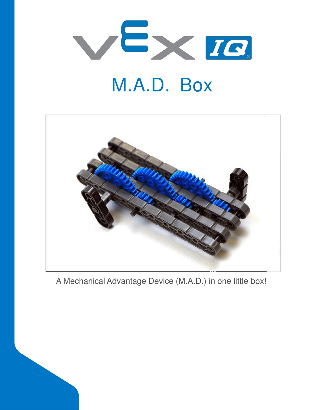
  38. Seek Section Roles Students can be organized groups of two to four students when engaging in the Seek section. The following roles can be utilized: Part Gatherer - This person ensures that the builders have all of the parts that they need for each step. Builder 1 - This person will build the first half of the M.A.D. Box (steps 1-5). Builder 2 - This person will build the second half of the M.A.D. Box (steps 6-10). Building Tips - This person ensures that the builders are not missing crucial pieces of information noted in the building tips for each step. If there are two students in each group, the students can each choose two roles. If there are three students in a group, one person can be the sole builder. If there are four students in a group, each student can have one role. Provide the list of roles and their definitions to the students. Once students are in their groups, allow the members to choose their role. Circulate the classroom and makes sure that every student has a role. There is an optional collaboration rubric on this page. Remind the students of roles throughout the exploration. For roles to work, students have to feel as though they will be held accountable for fulfilling those roles. Therefore, interject if you see a student taking over someone else s role or not fulfilling their assigned role. Reminders about who is supposed to be doing what can be useful interventions.

Related


More Related Content

giItT1WQy@!-/#giItT1WQy@!-/#giItT1WQy@!-/#giItT1WQy@!-/#giItT1WQy@!-/#giItT1WQy@!-/#giItT1WQy@!-/#giItT1WQy@!-/#giItT1WQy@!-/#