Caterpillar Cat 3512C INDUSTRIAL ENGINE (Prefix MLM) Service Repair Manual Instant Download (MLM00001 and up)
Please open the website below to get the complete manualnn//

Download Presentation

Please find below an Image/Link to download the presentation.
The content on the website is provided AS IS for your information and personal use only. It may not be sold, licensed, or shared on other websites without obtaining consent from the author. Download presentation by click this link. If you encounter any issues during the download, it is possible that the publisher has removed the file from their server.
E N D
Presentation Transcript
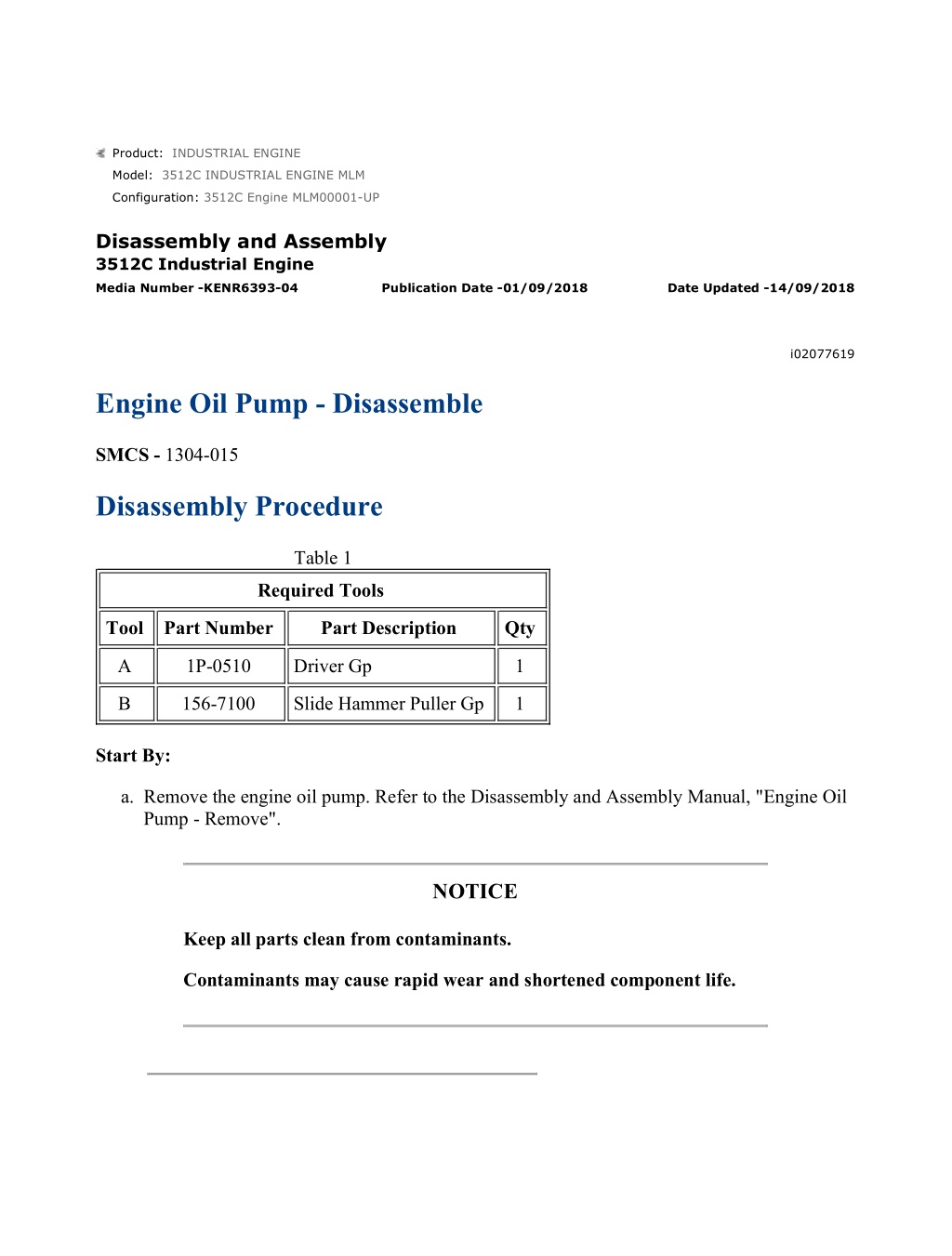
w 1/4(W) Product: INDUSTRIAL ENGINE Model: 3512C INDUSTRIAL ENGINE MLM Configuration: 3512C Engine MLM00001-UP Disassembly and Assembly 3512C Industrial Engine Media Number -KENR6393-04 Publication Date -01/09/2018 Date Updated -14/09/2018 i02077619 Engine Oil Pump - Disassemble SMCS - 1304-015 Disassembly Procedure Table 1 Required Tools Tool Part Number Part Description Qty A 1P-0510 Driver Gp 1 B 156-7100 Slide Hammer Puller Gp 1 Start By: a. Remove the engine oil pump. Refer to the Disassembly and Assembly Manual, "Engine Oil Pump - Remove". NOTICE Keep all parts clean from contaminants. Contaminants may cause rapid wear and shortened component life. https://127.0.0.1/sisweb/sisweb/techdoc/techdoc_print_page.jsp?returnurl=/sisweb/sisw... 2022/4/28
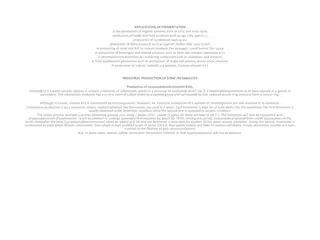
w 2/4(W) Illustration 1 g01005273 1. Remove adapter (1). Illustration 2 g01005318 Personal injury can result from parts and/or covers under spring pressure. Spring force will be released when covers are removed. Be prepared to hold spring loaded covers as the bolts are loosened. 2. Remove cover (2). Remove gasket (3), spring (4), and valve spool (5). https://127.0.0.1/sisweb/sisweb/techdoc/techdoc_print_page.jsp?returnurl=/sisweb/sisw... 2022/4/28
w 3/4(W) Illustration 3 g00591932 3. Remove cover assembly (6) and the gasket. Illustration 4 g00591936 4. Remove cover assembly (7). Illustration 5 g01050749 5. Use Tooling (A) in order to remove bearings (8) from cover assembly (7). https://127.0.0.1/sisweb/sisweb/techdoc/techdoc_print_page.jsp?returnurl=/sisweb/sisw... 2022/4/28
https://www.ebooklibonline.com Hello dear friend! Thank you very much for reading. Enter the link into your browser. The full manual is available for immediate download. https://www.ebooklibonline.com
w 4/4(W) Illustration 6 g00591963 6. Remove shaft assemblies (10) from body (9). Illustration 7 g01057505 7. Use Tooling (A) in order to remove two of the three bearings (11) from body (9). 8. Use Tooling (B) in order to remove the remaining bearing. https://127.0.0.1/sisweb/sisweb/techdoc/techdoc_print_page.jsp?returnurl=/sisweb/sisw... 2022/4/28
w 1/5(W) Product: INDUSTRIAL ENGINE Model: 3512C INDUSTRIAL ENGINE MLM Configuration: 3512C Engine MLM00001-UP Disassembly and Assembly 3512C Industrial Engine Media Number -KENR6393-04 Publication Date -01/09/2018 Date Updated -14/09/2018 i02063530 Engine Oil Pump - Assemble SMCS - 1304-016 Assembly Procedure Table 1 Required Tools Tool Part Number Part Description Qty A 1P-0510 Driver Group 1 NOTICE Keep all parts clean from contaminants. Contaminants may cause rapid wear and shortened component life. https://127.0.0.1/sisweb/sisweb/techdoc/techdoc_print_page.jsp?returnurl=/sisweb/sisw... 2022/4/28
w 2/5(W) Illustration 1 g01057511 1. Align bearings (11) in the body of the engine oil pump. Align the joints of the bearings to 45 15 degrees from the centerline of the bearing bores. 2. Use Tooling (A) in order to install bearings (11). The bearings must be 1.5 0.5 mm (0.06 0.02 inch) below the gear bore. Measure the inside diameter of the bearings after installation. The inside diameter of the bearings must be 31.811 0.013 mm (1.2524 0.0005 inch) after installation. Machine the bearing, if necessary. Illustration 2 g00591963 3. Install shaft assemblies (10) in body (9). https://127.0.0.1/sisweb/sisweb/techdoc/techdoc_print_page.jsp?returnurl=/sisweb/sisw... 2022/4/28
w 3/5(W) Illustration 3 g01057514 4. Ensure that dowels (12) are installed in cover assembly (7) at a distance of 6.0 0.5 mm (0.24 0.02 inch) above the surface of the cover. 5. Use Tooling (A) in order to install bearings (8) in cover assembly (7) with the bearing joints in the correct position. Illustration 4 g00591936 6. Place cover assembly (7) into position and install the bolts. https://127.0.0.1/sisweb/sisweb/techdoc/techdoc_print_page.jsp?returnurl=/sisweb/sisw... 2022/4/28
w 4/5(W) Illustration 5 g00591932 7. Ensure that the two pins in cover assembly (6) are installed at a distance of 6.0 1.0 mm (0.24 0.04 inch) above the surface of the cover. Install cover assembly (6). Illustration 6 g01005318 Improper assembly of parts that are spring loaded can cause bodily injury. To prevent possible injury, follow the established assembly procedure and wear protective equipment. 8. Place clean engine oil on valve spool (5). Install valve spool (5), spring (4), gasket (3), cover (2), and the bolts. https://127.0.0.1/sisweb/sisweb/techdoc/techdoc_print_page.jsp?returnurl=/sisweb/sisw... 2022/4/28
w 5/5(W) Illustration 7 g01005273 9. Install the gasket and adapter (1). Note: Refer to Specifications, "Engine Oil Pump" for more information. End By: a. Install the engine oil pump. Refer to Disassembly and Assembly, "Engine Oil Pump - Install". https://127.0.0.1/sisweb/sisweb/techdoc/techdoc_print_page.jsp?returnurl=/sisweb/sisw... 2022/4/28
w 1/3(W) Product: INDUSTRIAL ENGINE Model: 3512C INDUSTRIAL ENGINE MLM Configuration: 3512C Engine MLM00001-UP Disassembly and Assembly 3512C Industrial Engine Media Number -KENR6393-04 Publication Date -01/09/2018 Date Updated -14/09/2018 i02772985 Engine Oil Pump - Install SMCS - 1304-012 Installation Procedure NOTICE Keep all parts clean from contaminants. Contaminants may cause rapid wear and shortened component life. https://127.0.0.1/sisweb/sisweb/techdoc/techdoc_print_page.jsp?returnurl=/sisweb/sisw... 2022/4/28
w 2/3(W) Illustration 1 g01386297 1. Ensure that the O-ring seal is in position on elbow (8). Coat the O-ring seal with clean engine oil. Note: Before you install the engine oil pump, make sure that the shaft of the pump will turn by hand. The pump must have oil for lubrication before the pump is installed. 2. Use two people in order to install engine oil pump (10). The weight of engine oil pump (10) is approximately 36 kg (79 lb). Place engine oil pump (10) and elbow (8) into position. Make sure that the splines of the engine oil pump are properly meshed with the splines of the drive for the engine oil pump. Install bolts (9) that secure engine oil pump (10) and elbow (8). 3. Install bolts (7) to secure engine oil pump (10). 4. Make sure that the O-ring seal is in position on the tube and elbow (1). Coat the O-ring seals with clean engine oil. Install bolts (2). 5. Position adapter (5). Ensure that the gasket is in place and install bolts (3). Install bolts (4) and (6). 6. Fill the cooling system. Refer to the Operation and Maintenance Manual, "Refill Capacities". End By: https://127.0.0.1/sisweb/sisweb/techdoc/techdoc_print_page.jsp?returnurl=/sisweb/sisw... 2022/4/28
w 3/3(W) a. Install the fuel transfer pump. Refer to Disassembly and Assembly, "Fuel Transfer Pump - Install". https://127.0.0.1/sisweb/sisweb/techdoc/techdoc_print_page.jsp?returnurl=/sisweb/sisw... 2022/4/28
w 1/2(W) Product: INDUSTRIAL ENGINE Model: 3512C INDUSTRIAL ENGINE MLM Configuration: 3512C Engine MLM00001-UP Disassembly and Assembly 3512C Industrial Engine Media Number -KENR6393-04 Publication Date -01/09/2018 Date Updated -14/09/2018 i02773285 Engine Oil Filter Base - Remove - Spin-on Filters SMCS - 1306-011 Removal Procedure Table 1 Required Tools Tool Part Number Part Description Qty A 2P-8250 Strap Wrench Assembly 1 B 138-7575 Link Bracket 2 1. Remove the bolts that hold the clips for the harness assembly. Move the harness assembly out of the way. https://127.0.0.1/sisweb/sisweb/techdoc/techdoc_print_page.jsp?returnurl=/sisweb/sisw... 2022/4/28
w 2/2(W) Illustration 1 g01386630 2. Remove filters (9) with Tooling (A). 3. Remove bolts (5) that hold the retainers. Remove tube assembly (6). Remove adapter (10) from oil filter base (1). 4. Remove bolts (7) from the clamp assembly and relocate tube assembly (8). Remove the retainer and the O-ring seal from tube assembly (8). 5. Attach Tooling (B) to oil filter base (1). Attach a suitable lifting device to Tooling (B). The weight of oil filter base (1) is approximately 39 kg (86 lb). 6. Remove bolts (2) and (4) with the washers. Remove bolts (3) that hold oil filter base (1) to the engine. Remove oil filter base (1). https://127.0.0.1/sisweb/sisweb/techdoc/techdoc_print_page.jsp?returnurl=/sisweb/sisw... 2022/4/28
w 1/3(W) Product: INDUSTRIAL ENGINE Model: 3512C INDUSTRIAL ENGINE MLM Configuration: 3512C Engine MLM00001-UP Disassembly and Assembly 3512C Industrial Engine Media Number -KENR6393-04 Publication Date -01/09/2018 Date Updated -14/09/2018 i02774078 Engine Oil Filter Base - Disassemble - Spin-on Filters SMCS - 1306-015 Disassembly Procedure Start By: a. Remove the oil filter base. Refer to Disassembly and Assembly, "Engine Oil Filter Base - Remove". NOTICE Keep all parts clean from contaminants. Contaminants may cause rapid wear and shortened component life. https://127.0.0.1/sisweb/sisweb/techdoc/techdoc_print_page.jsp?returnurl=/sisweb/sisw... 2022/4/28
w 2/3(W) Illustration 1 g01386758 1. Remove bolts (4) and the washers. 2. Remove bracket (3) and support (2) from oil filter base (1). Personal injury can result from parts and/or covers under spring pressure. Spring force will be released when covers are removed. Be prepared to hold spring loaded covers as the bolts are loosened. https://127.0.0.1/sisweb/sisweb/techdoc/techdoc_print_page.jsp?returnurl=/sisweb/sisw... 2022/4/28
w 3/3(W) Illustration 2 g01386759 3. Remove the bolts and elbow (11) with the gasket. 4. Remove bolts (9) and the washers. Remove cover (8), gasket (7), spring (6), and plunger (5) from each base assembly. 5. Remove bolts (10), the washers, and the nuts that hold the base assemblies together. 6. If necessary, remove the studs from oil filter base (1). https://127.0.0.1/sisweb/sisweb/techdoc/techdoc_print_page.jsp?returnurl=/sisweb/sisw... 2022/4/28
w 1/3(W) Product: INDUSTRIAL ENGINE Model: 3512C INDUSTRIAL ENGINE MLM Configuration: 3512C Engine MLM00001-UP Disassembly and Assembly 3512C Industrial Engine Media Number -KENR6393-04 Publication Date -01/09/2018 Date Updated -14/09/2018 i02774609 Engine Oil Filter Base - Assemble - Spin-on Filters SMCS - 1306-016 Assembly Procedure Table 1 Required Tools Tool Part Number Part Description Qty A 9S-3263 Thread Lock Compound 1 NOTICE Keep all parts clean from contaminants. Contaminants may cause rapid wear and shortened component life. 1. Use the following procedure if the filter element studs were removed from the base assemblies: a. Apply Tooling (A) to the tapered end of the studs for a distance of 10.2 1.5 mm (0.40 0.06 inch). b. Install the studs in the base assemblies. Tighten the studs to a torque of 80 14 N m (60 10 lb ft). https://127.0.0.1/sisweb/sisweb/techdoc/techdoc_print_page.jsp?returnurl=/sisweb/sisw... 2022/4/28
w 2/3(W) Illustration 1 g01386759 Improper assembly of parts that are spring loaded can cause bodily injury. To prevent possible injury, follow the established assembly procedure and wear protective equipment. 2. Place the gaskets in position between base assemblies. Install bolts (10), the washers, and the nuts that hold the base assemblies together. 3. Place the gaskets and elbow (11) into position. Install the bolts. 4. Install plunger (5) and spring (6) into each of the base assemblies. 5. Place gaskets (7) and covers (8) into position. Install bolts (9) and the washers into oil filter base (1). https://127.0.0.1/sisweb/sisweb/techdoc/techdoc_print_page.jsp?returnurl=/sisweb/sisw... 2022/4/28
w 3/3(W) Illustration 2 g01386758 6. Position support (2) and bracket (3). Install bolts (4) and the washers into oil filter base (1). End By: a. Install the oil filter base. Refer to Disassembly and Assembly, "Engine Oil Filter Base - Install". https://127.0.0.1/sisweb/sisweb/techdoc/techdoc_print_page.jsp?returnurl=/sisweb/sisw... 2022/4/28
w 1/2(W) Product: INDUSTRIAL ENGINE Model: 3512C INDUSTRIAL ENGINE MLM Configuration: 3512C Engine MLM00001-UP Disassembly and Assembly 3512C Industrial Engine Media Number -KENR6393-04 Publication Date -01/09/2018 Date Updated -14/09/2018 i02774688 Engine Oil Filter Base - Install - Spin-on Filters SMCS - 1306-012 Installation Procedure Table 1 Required Tools Tool Part Number Part Description Qty B 138-7575 Link Bracket 2 NOTICE Keep all parts clean from contaminants. Contaminants may cause rapid wear and shortened component life. https://127.0.0.1/sisweb/sisweb/techdoc/techdoc_print_page.jsp?returnurl=/sisweb/sisw... 2022/4/28
w 2/2(W) Illustration 1 g01386630 1. Attach Tooling (B) and a suitable lifting device to oil filter base (1). The weight of oil filter base (1) is approximately 39 kg (86 lb). Lift oil filter base (1) into position. Install bolts (2) that hold oil filter base (1) to the engine. 2. Install bolts (2) and (4) with the washers. 3. Position the gaskets and adapter (10) and install the bolts. Position tube assembly (6) and install bolts (5) with the retainers. 4. Position tube assembly (8) and install the clamp assembly with bolts (7), the washers, and the nuts. 5. Ensure that the mounting surface for the oil filters is clean. Apply clean engine oil to the seals of the filters. Install filters (9) according to the instructions that are shown on the filters. Do not overtighten the filters. 6. Place the clips for the harness assembly into position. Install the bolts into the clips. 7. Fill the engine with oil. Refer to the Operation and Maintenance Manual, "Refill Capacities". https://127.0.0.1/sisweb/sisweb/techdoc/techdoc_print_page.jsp?returnurl=/sisweb/sisw... 2022/4/28
Suggest: For more complete manuals. Please go to the home page. https://www.ebooklibonline.com If the above button click is invalid. Please download this document first, and then click the above link to download the complete manual. Thank you so much for reading
w 1/2(W) Product: INDUSTRIAL ENGINE Model: 3512C INDUSTRIAL ENGINE MLM Configuration: 3512C Engine MLM00001-UP Disassembly and Assembly 3512C Industrial Engine Media Number -KENR6393-04 Publication Date -01/09/2018 Date Updated -14/09/2018 i02047059 Engine Oil and Water Pump Drive - Remove SMCS - 1313-011 Removal Procedure Start By: a. Remove the engine oil pump. Refer to Disassembly and Assembly, "Engine Oil Pump - Remove". b. Remove the water pump. Refer to Disassembly and Assembly, "Water Pump - Remove". NOTICE Keep all parts clean from contaminants. Contaminants may cause rapid wear and shortened component life. NOTICE Care must be taken to ensure that fluids are contained during performance of inspection, maintenance, testing, adjusting, and repair of the product. Be prepared to collect the fluid with suitable containers before opening any compartment or disassembling any component containing fluids. Refer to Special Publication, NENG2500, "Dealer Service Tool Catalog" for tools and supplies suitable to collect and contain fluids on Cat products. https://127.0.0.1/sisweb/sisweb/techdoc/techdoc_print_page.jsp?returnurl=/sisweb/sisw... 2022/4/28
w 2/2(W) Dispose of all fluids according to local regulations and mandates. Illustration 1 g00921410 1. Remove bolts (1) and rear adapter assembly (2). Illustration 2 g00921411 2. Remove bolts (4) and front adapter assembly (3). https://127.0.0.1/sisweb/sisweb/techdoc/techdoc_print_page.jsp?returnurl=/sisweb/sisw... 2022/4/28
https://www.ebooklibonline.com Hello dear friend! Thank you very much for reading. Enter the link into your browser. The full manual is available for immediate download. https://www.ebooklibonline.com