Optical Fiber Calibration System & Adaptive Power Supply by J. Cvach
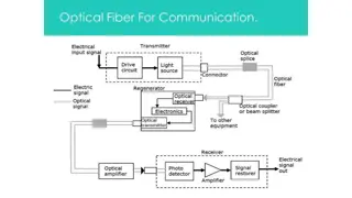
Introduction to an optical fiber calibration system and adaptive power supply developed by J. Cvach from the Institute of Physics, ASCR, Prague. The system includes an LED driver, notched fibers, and adaptive power supply for various applications, such as the calibration of the CALICE AHCAL and LHCb detectors. Details on the LED driver, optical connectors, QMB1a PIN LED, and the involvement in the COMPASS experiment at CERN are discussed.

Download Presentation

Please find below an Image/Link to download the presentation.
The content on the website is provided AS IS for your information and personal use only. It may not be sold, licensed, or shared on other websites without obtaining consent from the author. Download presentation by click this link. If you encounter any issues during the download, it is possible that the publisher has removed the file from their server.
E N D
Presentation Transcript
OPTICAL FIBER CALIBRATION SYSTEM & ADAPTIVE POWER SUPPLY * J. CVACH*,INSTITUTE OF PHYSICS, ASCR, PRAGUE Introduction LED driver Notched fibres Adaptive power supply Summary 1. 2. 3. 4. 5. _______________________________________ * On behalf of I. Pol k, J. Smol k, J. Kvasni ka, M. Janata, M. Koval uk from IPASCR and CALICE coll.
2 LCWS Beograd, October 7, 2014 J. Cvach, Optical fibre calibration system 1. Introduction Progress since LCWS13 Originally - an alternative calibration system for the CALICE AHCAL Now we look for application outside of ILD LHCb calibration of Scintillating Fibre Tracker in LHCb Upgrade program COMPASS - ECAL0 calibration
3 LCWS Beograd, October 7, 2014 J. Cvach, Optical fibre calibration system optical connector 2. LED driver QMB1a PIN LED Works on the principle of a DC- to-DC power converter, Vout > Vin Modifications for COMPASS ECAL0, CERN Variable amplitude (0 - 1 A) Repetition rate up to 100 kHz Fixed pulse width (2.4 3.5 ns) Smooth pulse shape (half-sine shape) PCB size 30 140 mm2 to match the size of tiles Fixed amplitude (~1 A peak) Repetition rate ~ 1 Hz, steady Fixed pulse width (10 - 20 ns) Amplitude monitored by PIN diode close to LED for feedback to keep the constant light No restriction on the PCB size
4 LCWS Beograd, October 7, 2014 J. Cvach, Optical fibre calibration system Germany CERN-small China-Taipei Czech France Israel Italy Japan India Poland Portugal Russia USA COMPASS - II experiment Fixed target experiment at SPS Study of hadron structure, hadron spectroscopy with muon & hadron beams Polarised NH3 target Data taking from 2002, resumed in 2014 with beam Detector 60 m long, various subdetectors (incl. RICH, SciFi, pioneered GEMs) Our participation together with Dubna group of A. Nagaytsev, Z. Krumstein on ECAL0, ready in 2016 Shashlyk calo for s to study the generalized PDFs p ECAL0
5 LCWS Beograd, October 7, 2014 J. Cvach, Optical fibre calibration system Electromagnetic calorimeter ECAL0 ECAL0 module 194 modules made as a sandwich read by WLS fibres going through 109 Pb & scint. perforated layers 9 polystyrene scint. tiles 40x40x1.5 mm3 read by 16 fibres Thermo-stabilized by Peltier elements at 15 0.05 C 15 X0, E/E ~ 9%/ E 1% Here we connect with our fibre Beam tests in e- CERN T9 beam 3 x 3 modules with MAPD Good resolution & linearity
6 LCWS Beograd, October 7, 2014 J. Cvach, Optical fibre calibration system Photodetectors: MAPD vs. MPPC Two types considered: MAPD 3N Zecotek, Singapore MPPC S12572-010C Hamamatsu x106 x105 Sensitive area 3 x 3 mm2, reads 16 fibres Gain ~ 2.105 # pixels 135 000 vs. 90 000 Dark rate ~ 106 Datasheet values differ from the reality measurement done in 2014 (A. Richter et al., Warsaw University of Technology) Conclusions: MPPC looks as a good replacement for MAPD MPPC S12572-010C
7 LCWS Beograd, October 7, 2014 J. Cvach, Optical fibre calibration system Monitoring system for ECAL0 LED driver Fibre distribution system Variable amplitude for amplitude scan (option) No interest in single p.e. spectra One LED illuminates 50 modules high intensity light Amplitude stability PIN diode feedback is a must averaging over > 10 pulses in C Pulse width ~ 20 ns external toroidal inductor Modification of the QMB1a is ongoing High intensity 8 mm blue LED with optical connector fibre bundle with 50 fibres with 1 mm Length fibres in bundle is 2.5 m See face of the bundle of fibres in a connector illuminated by daylight and a blue 8 mm LED
8 LCWS Beograd, October 7, 2014 J. Cvach, Optical fibre calibration system Monitoring system for ECAL0 at present Scheme of the new LED driver QMB1b and PCB for PIN preamp Optical distribution of LED light pulses Calibration light to 194 ECAL0 channels Light spread ~ 10% 10000 p.e. @ MPPC 4 connectors with 55 fibres in autumn 2015 Fibre with connector on the ECAL0 side Bunch of fibres, light-mixer and socket on the QMB1b side PIN photodiode Tests of the fully equipped board 1% long term stability Interface CAN USB Trigger LVDS NIM SW interface module for PC Autumn 2015 4 channels for tests
9 LCWS Beograd, October 7, 2014 J. Cvach, Optical fibre calibration system 3. Notched fibres milling machine 3d movement Steps in 10 m, accuracy 15 m Template configured for AHCAL tile geometry Depth of the notch increases from the beginning of the fibre to its end to maintain the same light intensity CNC-multi-tool ML 1000F Computer controlled milling of a notch in steps & measurement of light emitted from the notch Fully automatic milling of notches was foreseen Potentially not possible with the current machine
10 LCWS Beograd, October 7, 2014 J. Cvach, Optical fibre calibration system Notched fibres spread of light DESY tests in 2013 Production in 2014 20% No significant improvement in time Goal for the spread of light 15% not reached! of light over 24 notches is 5% - good! Light output from different fibres is homogenous Proposal on the design of a new instrument Cost estimate 20 k Average light output 9 fibres
11 LCWS Beograd, October 7, 2014 J. Cvach, Optical fibre calibration system 4. Adaptive power supply for SiPMs Gain stabilization at 1% level at variable temperature of environment AIDA-MS-45: together with Uni Bergen successfully fulfilled see talk of G. Eigen at Vienna 2014 AIDA annual meeting & AIDA-NOTE-2014-002 Temperature correction applied via analog electronic feedback Provide regulated DC voltage 15-90 V (or up to 450 V) V/ T slope for a SiPM set in the range 5-100 mV/ K Tested on KETEK, CPTA sensors, they cluster into 2 groups: dV/dT Vbias More demanding task gain stabilization in the whole AHCAL AIDA II CPTA #857 ADApower box
12 LCWS Beograd, October 7, 2014 J. Cvach, Optical fibre calibration system Modification of Power & DIF board ADApower box Analog circuit solution is more advanced over ADC P DAC version (digital solution via slow control) ADC and DAC should have at least 16 bit resolution with proper linearity and fidelity not easy task 16 bit DAC can control HV regulator in steps of 1 mV (65535 x 1 mV = 65.5 V) in range of 15 to 80 V Solution currently under discussion I. Pol k M. Reinecke ON/OFF & VOUT Set is controlled by DAC circuit SiPM P in PWR board I. Pol k
13 LCWS Beograd, October 7, 2014 J. Cvach, Optical fibre calibration system 5. Summary We are trying to adapt our experience with LED calibration + notched fibre light distribution system to another experiments Improved QMB1b LED driver (with the PIN feedback) selected for upgrade of COMPASS experiment with ECAL0 calorimeter Interest for notched fibre light distribution in the LHCb Upgrade Scintillating Fibre Tracker Survey for the improved machine for notched fibre milling Work on adaptive HV power board is ongoing (analog/digital) for AHCAL The new task for temperature compensation SiPM gain included in the foreseen AIDA II project