Understanding Shell Elements for Thin Structure Modeling
Shell elements, such as those in ANSYS SHELL, are crucial for modeling thin structures experiencing bending. Real constants and assumed behaviors impact stress distribution, while boundary conditions like clamped edges and simply supported sections play a key role. In-class problems help apply theoretical knowledge to practical scenarios, enhancing understanding of stress and displacement calculations.

Download Presentation

Please find below an Image/Link to download the presentation.
The content on the website is provided AS IS for your information and personal use only. It may not be sold, licensed, or shared on other websites without obtaining consent from the author. Download presentation by click this link. If you encounter any issues during the download, it is possible that the publisher has removed the file from their server.
E N D
Presentation Transcript
Shell Elements Jake Blanchard Spring 2008
Shell (or plate) Elements These are typically planar elements They are used to model thin structures which will experience bending It is difficult to model thin structures with 3- D elements, because many are needed through thickness to capture bending behavior Element features 6 DOF per node (3 translations and 3 rotations) for 3-D elements Bending modes are included More than 1 stress at each point on the element
Shell Elements in ANSYS SHELL 61 = 2-node, axisymmetric shell 4 DOF/node (3 translation and one rotation) SHELL 208 = like 61, but finite strain SHELL 209 = like 208, but with midside node (3-node element) SHELL 28 = shear twist panel 3 DOF/node (3 translation or 3 rotation) SHELL 41 = 3-D quad or triangle with membrane only SHELL 43 = 4-node shell with 6 DOF/node (plastic) SHELL 63 = 4-node shell with 6 DOF/node (elastic only) SHELL 93 = Like 63, but with midside nodes SHELL 150 = 8-node p-element SHELL 181 = 4-node, finite strain SHELL 281 = 8-node, finite strain
Real Constants TK(I), TK(J), TK(K), TK(L)
Assumed Behavior Stresses are assumed to be linear through the thickness Middle surface has 0 bending stress Membrane stresses are uniform over thickness
Boundary Conditions Clamped Edge No displacements or rotations Simply-Supported Edge No displacements Rotation is allowed perpendicular to edge
Simply Supported
In-Class Problems Consider a flat plate 1 m on each side 10 cm thick E=200 GPa, =0.3 Uniform transverse pressure on entire face (1 MPa) Two opposite sides are clamped, other two are simply supported Expect max stress of 42 MPA, max displacement of 0.1 mm
Circular plate Plate is 1 m diameter (2R), 1 cm thick Transverse pressure (1 MPa) is applied over inner circle with diameter of 20 cm (2r0) E=200 Gpa, =0.3 2 2 r R p = 0 16 Et v max D 3 = D ( 1 ) 2 12
Pressure Vessel End-Cap is hemispherical R=2.2 m, t=0.2 m P=1 MPa E=200 Gpa, =0.3 R 2R

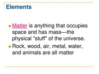
 Elements")