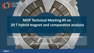
US Magnet Development Program
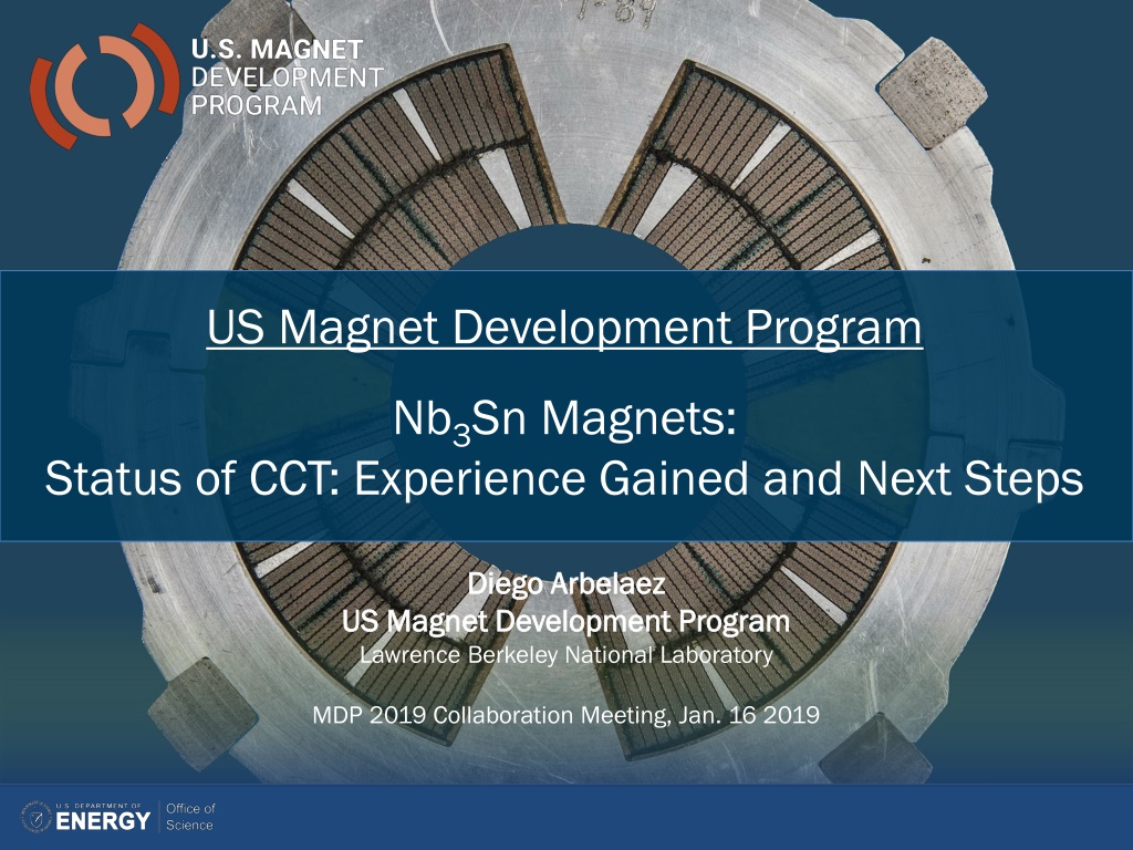
Diego Arbelaez
US Magnet Development Program
Lawrence Berkeley National Laboratory
MDP 2019 Collaboration Meeting, Jan. 16 2019
US Magnet Development Program
Nb
3
Sn Magnets:
Status of CCT: Experience Gained and Next Steps
Outline
•
Motivation
•
CCT development history and recent results
•
CCT5 development and test results
•
CCT program next steps
o
Subscale plan and progress
o
Plan towards higher field / hybrid CCT dipole magnets
•
Other topics covered in this session
o
CCT Modeling (Lucas Brouwer)
o
CCT Instrumentation and Test Results (Maxim Marchevsky)
CCT Motivation
•
“A critical aspect of the program is to aggressively investigate
innovative new design concepts that may prove to have better
performance at a lower cost per T-m”
•
“The main motivation is in the area of mechanical stresses:
preliminary calculations show dramatic reduction in azimuthal
stresses, effectively eliminating these stresses as limitations in the
magnet design”
•
“the concept will allow for conductor grading and for the
implementation of HTS materials for very high-field CCT magnet
designs”
3
CCT Dipole Concept Can Offer Several
Advantages Over Other Magnet Designs
•
Canted windings in opposing directions produce dipole field (excellent field quality)
•
Windings are placed in a mandrel with grooves - Ribs in mandrel intercept Lorentz force
leading to substantially reduced azimuthal stress
•
Ease of fabrication and minimal tooling can lead to reduced cost
•
Fabrication methods and modularity of approach leads to natural extension for HTS
materials
4
Transverse current density with cos-theta
distribution approaches a perfect dipole current
density distribution
Ribs Intercept Lorentz Force
Winding Geometry
CCT Design Requires Minimal Amount of
Tooling and Parts When Compared to
Traditional Dipole Magnets
•
Aluminum Bronze mandrels incorporate features for stress management
and cable positioning
•
Minimal tooling is required for heat treatment and epoxy impregnation
5
Coil Winding
Machined Mandrel
Heat Treatment with SST
Sheet and Clamps
Coil Impregnation
Early Focus of CCT Program is on 2-Layer
Model Magnets Followed by Multi-Layer
Magnet Development
6
History of Previous CCT Dipole Tests at
LBNL
7
CCT1
•
2.5 T short-sample dipole
•
50 mm clear bore
•
8 strd. NbTi cable
•
not impregnated
•
11/2013
:
tested up to 2.5 T
CCT2
•
5.3 T short-sample dipole
•
90 mm clear bore
•
23 strd. NbTi cable (0.8 mm SSC Inner)
•
epoxy impregnated
•
5/2015:
tested up to 4.7 T
CCT3/4
•
10.5 T bore field at round wire short-sample
•
90 mm clear bore
•
CCT3 03/2016:
reached bore field of 7.4 T (conductor damage)
•
CCT4 08/2017:
reached bore field of 9.1 T (substantial training)
CCT1
CCT2
CCT3/4
Test Results for CCT3 led to Design Changes in
the Conductor Groove Geometry for CCT4
•
Cable was protruding above mandrel
surface after heat treatment for CCT3
•
Dedicated experiments were performed
to understand mandrel/cable behavior
during heat treatment
•
Groove geometry was modified for CCT4
to avoid conductor damage during
assembly
8
CCT3 Quench Current
•
CCT3 reached 68% of short sample
current after 28 quenches
•
Higher current can be achieved at higher
ramp rates
•
Observed instability in magnet test
starts at ~460A per strand (likely cause
was conductor damage)
CCT4 Results Lead to Focus on Training
Reduction for CCT5
•
Reduction in training is the main
focus for CCT5
o
Impregnation material (CCT5 uses
tougher epoxy)
o
Frictional interfaces (CCT5 uses shim
interface)
9
•
Reached 86% of round wire short
sample after 85 quenches
•
Maximum current is 16.7 kA
•
Maximum bore field is 9.14 T (90 mm
aperture)
•
Magnet exhibits long training but good
memory after thermal cycle
Stress at Layer-to-Layer Interface
Localization of Quenches
from Acoustic Signals
2-Layer CCT Nb
3
Sn Plan
(CCT Technology Development)
10
•
Conductor damage
•
Field quality
•
Cost and scalability
•
Training
Reminder: CCT3/CCT4 Layers Were
Assembled Into The Shell And Impregnated
As One Unit
11
Step 1. Assemble Layers
11
Step 2. Layers 1+2 into shell
Step 3. all impregnated together
with the shell used as tooling
•
Reacted coils are assembled together with G10 shim
between layers
•
Coils are inserted into the Aluminum shell and the
entire assembly is vacuum impregnated with epoxy
•
Areas of unfilled epoxy remain between the layers
o
G10 shim has to be substantially thinner than gap between
layers due to distortion of the mandrels during heat treatment
CCT5: New Method Developed for Coupling of
Individually Potted Layers (Bend-and-Shim)
•
Contact location between layers is controlled by using shims and Kapton
bags that are filled with glass and epoxy
o
Allows for control of contact location
o
Fracture in interface epoxy does not propagate to the coil
o
Improved cooling at the pole regions from direct contact with LHe
•
Directional preload to reduce energized stress can be applied by bending
layers or shell, filling and curing epoxy in bent state, releasing bending
pressure
12
New Assembly Method Requires
Epoxy
Impregnation of Individual CCT Coils
•
Coils are impregnated with mix 61 epoxy
•
Did not deviate too far from usual LBNL potting procedures to avoid
delaying CCT5 test
o
Use vacuum vessel for impregnation
o
Seal coil ends with Aluminum end plugs as with CCT3/4
o
Sealing of external coil surface is done with inexpensive consumable
materials
•
Use common techniques and materials from vacuum bag process
o
Peel ply to minimize epoxy on surface of mandrel
o
Flow media for epoxy flow
o
Use Nylon vacuum bag
o
Use shrink tape to compress the compress the bag and flow media layer
tightly onto the mandrel
13
Porous Flow Media for
Epoxy Flow
Potting of Test Coil
Release Film Leaves Clean
Surface
Vacuum Impregnation of CCT5 1 Meter
Coils using New Process Was Successful
•
CCT5 coils were successfully
impregnated with new process
•
Instrumentation traces were
included in the impregnation
14
Wrapped Coil After Impregnation
Bend and Shim Assembly Process was
Performed after Vacuum Impregnation of the
Coils
•
No bending for inner/outer layer assembly
•
Bending of the shell for coils/shell assembly
•
CTD 528 epoxy was used due to cryogenic toughness, sufficiently long
working life, and near room temperature cure
15
CCT Layers after Filling and
Curing of Epoxy Filled Kapton Bag
Shell and Coils in Press After Epoxy Cure
Instrumentation
•
Voltage taps at every 5
th
turn in inner layer (sparse on outer layer)
•
Acoustic sensors at coil ends and inside of the bore (new development)
•
Strain gages on shell
•
Spot heater with associated voltage taps and thermometer in groove
16
Quench Localization With Acoustic Sensors
Inner Layer Voltage Tap Layout
* Details in talk by M. Marchevsky
CCT5 Shows Initial Improvement in Training
Followed by Similar Behavior to CCT4
•
CCT4 conductor has higher Ic (CCT4: 54/61 RRP, CCT5: 108/127 RRP)
•
First quench at 69% of short sample, magnet reached 88% of short sample
after 59 training quenches
•
After initial improvement training rate is similar to CCT4
•
After approx. quench #20 there are many detraining quenches with large drops
in quench current (similar to CCT4 after approx. quench #30)
17
Quench Current Relative to SSL
Quench Current
Test 1
Test 2
Thermal Cycle
Segments Where Quench Initiated Have
Been Recorded From Voltage Taps
•
Quench locations are distributed over the entire coil
•
Somewhat higher concentration of quenches towards the ends
18
Sequential Quench Locations
Quench Current
Coil Segments
1
13
* Segments 9,10,11 and segments 5,6 were combined for test 2
* It is assumed that quenches are uniformly distributed in each sub-segment
CCT5 Test Observations and Conclusions
•
Improvement in early training (e.g. first quench current), but similar training
after initial section
•
Initial improvement likely due to change of epoxy and interface condition
between layers
•
All quenches in layer 1
•
Significant changes to epoxy and interface between layers, yet similar training
after initial improvement
•
This suggests that we focus on stress in cable and cable/groove interface (plan
for subscale magnet testing)
•
Surface quality for bonding is known to be poor due to residue deposit on the
mandrel surface after heat treatment (good topic for technology section)
•
Next steps for CCT5
o
Continue data analysis
o
Magnet disassembly and inspection
19
A Subscale Program for CCT Will Increase The
Speed of Technology Development
•
Motivation
o
Allows for faster turn-around to understand CCT
behavior
o
Can be tested in small cryostat
•
Design
o
5.2 T bore field and small mandrels and cables
o
Operate at higher Lorentz force
o
For nominal design normal stress is comparable
and shear stress is about half CCT5
•
Better understanding of CCT magnets
o
Testing of epoxies and interfaces
o
Test of assembly methods
o
Test of new instrumentation methods
20
Lorentz force density
peaks at 4.5 T
CCT Subscale
CCT 2-Layer
Lorentz Force
Initial Subscale Testing will Focus on
Understanding effect of cable and
cable/groove interface stress on training
•
CCT concept leads to reduced normal stress on conductor
•
Tradeoff between normal stress and shear stress at the cable/groove
interface
•
Shear stress can be reduced by reducing spar thickness but normal stress
will increase (accumulation of azimuthal force towards midplane +
bending of layers) (*
see L. Brouwer talk)
•
First set of tests
o
Nominal configuration (approximates CCT5) to verify that training is present
and subscale magnets can be useful tool to study training
o
Test subscale magnets with thin and thick spars to determine how the stress
state affects training
•
Future testing to improve cable/groove interface
o
Investigate methods for improving adhesion (surface modification)
o
Investigate methods of cleaning surfaces and coils
o
Investigate use of other materials for impregnation
21
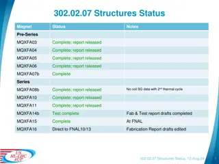
CCT Subscale Status
•
First subscale magnet is being fabricated (coils have been
heat treated)
•
Testing of first magnet in March
•
Second test campaign (2-3 magnets) in July
•
Testing of cable/groove interface improvements will require
separate small scale testing to identify promising
technologies and requires further planning
22
Multi-Layer CCT and Hybrid
Demonstration
•
4-Layer CCT Design with option for insert
o
Target bore dipole field of 12
–
13 T operating at ~ 80 - 85% of
short sample to allow for insert coils
o
Bore size of 90
–
120 mm (depends on HTS needs and results of
magnet design study)
•
Initial design work has started
•
Expect to have conceptual design in July
o
Magnetic analysis
o
Stress analysis
o
Quench protection analysis
•
Detailed design would occur after review of conceptual
design
23
Summary
•
CCT program focuses on new and innovative design of dipole
magnets
•
CCT technology and understanding has advanced through the
development of two layer models
•
New potting and assembly methods were developed for CCT5
•
Improvements were made to training behavior but substantial
training is still present
•
Subscale CCT will allow for more focused experiments on
training and mechanical behavior
•
Work on next steps for CCT development (4-layer magnet) is in
the early design stage
24
This content discusses the current status and future plans for Nb3Sn magnets in the US Magnet Development Program. It covers the motivation behind CCT development, recent results, advantages of the dipole concept, minimal tooling requirements, and more. The focus is on innovative design concepts to enhance performance and reduce costs in magnet development.

Download Presentation

Please find below an Image/Link to download the presentation.
The content on the website is provided AS IS for your information and personal use only. It may not be sold, licensed, or shared on other websites without obtaining consent from the author.If you encounter any issues during the download, it is possible that the publisher has removed the file from their server.
You are allowed to download the files provided on this website for personal or commercial use, subject to the condition that they are used lawfully. All files are the property of their respective owners.
The content on the website is provided AS IS for your information and personal use only. It may not be sold, licensed, or shared on other websites without obtaining consent from the author.
E N D
Presentation Transcript
US Magnet Development Program Nb3Sn Magnets: Status of CCT: Experience Gained and Next Steps Diego Arbelaez Diego Arbelaez US Magnet Development Program US Magnet Development Program Lawrence Berkeley National Laboratory MDP 2019 Collaboration Meeting, Jan. 16 2019
Outline Motivation CCT development history and recent results CCT5 development and test results CCT program next steps o Subscale plan and progress o Plan towards higher field / hybrid CCT dipole magnets Other topics covered in this session o CCT Modeling (Lucas Brouwer) o CCT Instrumentation and Test Results (Maxim Marchevsky)
CCT Motivation A critical aspect of the program is to aggressively investigate innovative new design concepts that may prove to have better performance at a lower cost per T-m The main motivation is in the area of mechanical stresses: preliminary calculations show dramatic reduction in azimuthal stresses, effectively eliminating these stresses as limitations in the magnet design the concept will allow for conductor grading and for the implementation of HTS materials for very high-field CCT magnet designs 3
CCT Dipole Concept Can Offer Several Advantages Over Other Magnet Designs Canted windings in opposing directions produce dipole field (excellent field quality) Windings are placed in a mandrel with grooves - Ribs in mandrel intercept Lorentz force leading to substantially reduced azimuthal stress Ease of fabrication and minimal tooling can lead to reduced cost Fabrication methods and modularity of approach leads to natural extension for HTS materials Ribs Intercept Lorentz Force Winding Geometry ~ cos zJ Transverse current density with cos-theta distribution approaches a perfect dipole current density distribution 4
CCT Design Requires Minimal Amount of Tooling and Parts When Compared to Traditional Dipole Magnets Aluminum Bronze mandrels incorporate features for stress management and cable positioning Minimal tooling is required for heat treatment and epoxy impregnation Coil Winding Machined Mandrel Coil Impregnation Heat Treatment with SST Sheet and Clamps 5
Early Focus of CCT Program is on 2-Layer Model Magnets Followed by Multi-Layer Magnet Development 6
History of Previous CCT Dipole Tests at LBNL CCT1 CCT1 CCT1 CCT2 CCT2 CCT3/4 CCT3/4 2.5 T short-sample dipole 50 mm clear bore 8 strd. NbTi cable not impregnated 11/2013: tested up to 2.5 T tested up to 2.5 T CCT2 5.3 T short-sample dipole 90 mm clear bore 23 strd. NbTi cable (0.8 mm SSC Inner) epoxy impregnated 5/2015: tested up to tested up to 4.7 CCT3/4 4.7 T T 10.5 T bore field at round wire short-sample 90 mm clear bore CCT3 03/2016: reached bore field of 7.4 T (conductor damage) reached bore field of 7.4 T (conductor damage) CCT4 08/2017: reached bore field of 9.1 T (substantial training) reached bore field of 9.1 T (substantial training) 7
Test Results for CCT3 led to Design Changes in the Conductor Groove Geometry for CCT4 Cable was protruding above mandrel surface after heat treatment for CCT3 Dedicated experiments were performed to understand mandrel/cable behavior during heat treatment Groove geometry was modified for CCT4 to avoid conductor damage during assembly CCT3 reached 68% of short sample current after 28 quenches Higher current can be achieved at higher ramp rates Observed instability in magnet test starts at ~460A per strand (likely cause was conductor damage) CCT3 Quench Current 14000 Cable Position After CCT3 HT Cable Position After CCT3 HT CCT 4 Groove Geometry CCT 4 Groove Geometry 20 A/s 50 A/s 75 A/s 100 A/s 200 A/s 13000 Quench current (A) 12000 11000 10000 9000 0 5 10 15 20 25 30 Quench # 8
CCT4 Results Lead to Focus on Training Reduction for CCT5 Reduction in training is the main focus for CCT5 o Impregnation material (CCT5 uses tougher epoxy) o Frictional interfaces (CCT5 uses shim interface) Reached 86% of round wire short sample after 85 quenches Maximum current is 16.7 kA Maximum bore field is 9.14 T (90 mm aperture) Magnet exhibits long training but good memory after thermal cycle CCT4 Training Behavior Stress at Layer-to-Layer Interface After Thermal Cycle Localization of Quenches from Acoustic Signals 9
2-Layer CCT Nb3Sn Plan (CCT Technology Development) CCT3 CCT4 CCT5 Bore size [mm] 90 90 90 1.25 mm gap at pole RRP 54/61 Ta doped 1.65 mm gap at pole RRP 108/127 Ti doped Groove design constant width RRP 54/61 Ta doped Conductor Conductor damage Field quality Cost and scalability Training HT Temp [C] Potting configuration 650 660 665 individual layers full magnet full magnet Epoxy Layer-to-layer interface CTD-101K CTD-101K FSU Mix 61 bonded mold released bend & shim 10
Reminder: CCT3/CCT4 Layers Were Assembled Into The Shell And Impregnated As One Unit Reacted coils are assembled together with G10 shim between layers Coils are inserted into the Aluminum shell and the entire assembly is vacuum impregnated with epoxy Areas of unfilled epoxy remain between the layers o G10 shim has to be substantially thinner than gap between layers due to distortion of the mandrels during heat treatment Step 3. all impregnated together with the shell used as tooling Step 1. Assemble Layers Layer 2 Step 2. Layers 1+2 into shell Layer 1 Linear driver G10 slip plane 11
CCT5: New Method Developed for Coupling of Individually Potted Layers (Bend-and-Shim) Contact location between layers is controlled by using shims and Kapton bags that are filled with glass and epoxy o Allows for control of contact location o Fracture in interface epoxy does not propagate to the coil o Improved cooling at the pole regions from direct contact with LHe Directional preload to reduce energized stress can be applied by bending layers or shell, filling and curing epoxy in bent state, releasing bending pressure epoxy filled Kapton bag Force Release After Cure shell Directional Pre-Load on Coils layer 1 layer 2 Applied Force 12
New Assembly Method Requires Epoxy Impregnation of Individual CCT Coils Coils are impregnated with mix 61 epoxy Did not deviate too far from usual LBNL potting procedures to avoid delaying CCT5 test o Use vacuum vessel for impregnation o Seal coil ends with Aluminum end plugs as with CCT3/4 o Sealing of external coil surface is done with inexpensive consumable materials Use common techniques and materials from vacuum bag process o Peel ply to minimize epoxy on surface of mandrel o Flow media for epoxy flow o Use Nylon vacuum bag o Use shrink tape to compress the compress the bag and flow media layer tightly onto the mandrel Potting of Test Coil Release Film Leaves Clean Surface Porous Flow Media for Epoxy Flow 13
Vacuum Impregnation of CCT5 1 Meter Coils using New Process Was Successful Instrumentation Trace After Potting CCT5 coils were successfully impregnated with new process Instrumentation traces were included in the impregnation V taps Thermometer Heater Wrapped Coil After Impregnation 14
Bend and Shim Assembly Process was Performed after Vacuum Impregnation of the Coils No bending for inner/outer layer assembly Bending of the shell for coils/shell assembly CTD 528 epoxy was used due to cryogenic toughness, sufficiently long working life, and near room temperature cure CCT Layers after Filling and Curing of Epoxy Filled Kapton Bag Shell and Coils in Press After Epoxy Cure 15
Instrumentation Voltage taps at every 5th turn in inner layer (sparse on outer layer) Acoustic sensors at coil ends and inside of the bore (new development) Strain gages on shell Spot heater with associated voltage taps and thermometer in groove Quench Localization With Acoustic Sensors * Details in talk by M. Marchevsky Inner Layer Voltage Tap Layout A9 A9 A10 A10 A11 A11 A12 A12 A13 A13 A14 A14 A15 A15 A2 A2 A3 A3 A4 A4 A5 A5 A6 A6 A7 A7 A8 A8 16
CCT5 Shows Initial Improvement in Training Followed by Similar Behavior to CCT4 CCT4 conductor has higher Ic (CCT4: 54/61 RRP, CCT5: 108/127 RRP) First quench at 69% of short sample, magnet reached 88% of short sample after 59 training quenches After initial improvement training rate is similar to CCT4 After approx. quench #20 there are many detraining quenches with large drops in quench current (similar to CCT4 after approx. quench #30) Quench Current Relative to SSL Quench Current Test 2 Test 1 Thermal Cycle 17
Segments Where Quench Initiated Have Been Recorded From Voltage Taps Quench locations are distributed over the entire coil Somewhat higher concentration of quenches towards the ends High field region Coil Segments 13 1 Sequential Quench Locations Quench Current * Segments 9,10,11 and segments 5,6 were combined for test 2 * It is assumed that quenches are uniformly distributed in each sub-segment 18
CCT5 Test Observations and Conclusions Improvement in early training (e.g. first quench current), but similar training after initial section Initial improvement likely due to change of epoxy and interface condition between layers All quenches in layer 1 Significant changes to epoxy and interface between layers, yet similar training after initial improvement This suggests that we focus on stress in cable and cable/groove interface (plan for subscale magnet testing) Surface quality for bonding is known to be poor due to residue deposit on the mandrel surface after heat treatment (good topic for technology section) Next steps for CCT5 o Continue data analysis o Magnet disassembly and inspection 19
A Subscale Program for CCT Will Increase The Speed of Technology Development Lorentz Force Motivation o Allows for faster turn-around to understand CCT behavior o Can be tested in small cryostat Design o 5.2 T bore field and small mandrels and cables o Operate at higher Lorentz force o For nominal design normal stress is comparable and shear stress is about half CCT5 Better understanding of CCT magnets o Testing of epoxies and interfaces o Test of assembly methods o Test of new instrumentation methods Lorentz force density peaks at 4.5 T CCT Subscale CCT 2-Layer 20
Initial Subscale Testing will Focus on Understanding effect of cable and cable/groove interface stress on training CCT concept leads to reduced normal stress on conductor Tradeoff between normal stress and shear stress at the cable/groove interface Shear stress can be reduced by reducing spar thickness but normal stress will increase (accumulation of azimuthal force towards midplane + bending of layers) (*see L. Brouwer talk) First set of tests o Nominal configuration (approximates CCT5) to verify that training is present and subscale magnets can be useful tool to study training o Test subscale magnets with thin and thick spars to determine how the stress state affects training Future testing to improve cable/groove interface o Investigate methods for improving adhesion (surface modification) o Investigate methods of cleaning surfaces and coils o Investigate use of other materials for impregnation 21
CCT Subscale Status First subscale magnet is being fabricated (coils have been heat treated) Testing of first magnet in March Second test campaign (2-3 magnets) in July Testing of cable/groove interface improvements will require separate small scale testing to identify promising technologies and requires further planning 22
Multi-Layer CCT and Hybrid Demonstration 4-Layer CCT Design with option for insert o Target bore dipole field of 12 13 T operating at ~ 80 - 85% of short sample to allow for insert coils o Bore size of 90 120 mm (depends on HTS needs and results of magnet design study) Initial design work has started Expect to have conceptual design in July o Magnetic analysis o Stress analysis o Quench protection analysis Detailed design would occur after review of conceptual design 23
Summary CCT program focuses on new and innovative design of dipole magnets CCT technology and understanding has advanced through the development of two layer models New potting and assembly methods were developed for CCT5 Improvements were made to training behavior but substantial training is still present Subscale CCT will allow for more focused experiments on training and mechanical behavior Work on next steps for CCT development (4-layer magnet) is in the early design stage 24