Understanding Total Hull Resistance in Ship Design
Learn about the total hull resistance calculations in ship design, including factors like air resistance, wave-making resistance, and viscous resistance. Explore how these components contribute to the total resistance a ship experiences during motion.

Download Presentation

Please find below an Image/Link to download the presentation.
The content on the website is provided AS IS for your information and personal use only. It may not be sold, licensed, or shared on other websites without obtaining consent from the author. If you encounter any issues during the download, it is possible that the publisher has removed the file from their server.
You are allowed to download the files provided on this website for personal or commercial use, subject to the condition that they are used lawfully. All files are the property of their respective owners.
The content on the website is provided AS IS for your information and personal use only. It may not be sold, licensed, or shared on other websites without obtaining consent from the author.
E N D
Presentation Transcript
Resistance & Froude Expansion Sections 7.5-7.7
Total Hull Resistance EHP Calculation Total Hull Resistance (RT) The force that the ship experiences opposite to the motion of the ship as it moves.
Coefficient of Total Hull Resistance Non-dimensional value of total resistance lb ?? 0.5? ??2 ? ??= ??2 non dimensional 2 ?? ?2 ??4 ?? ? On Equation Sheet (Ch. 7) Where: ??= Coefficient of total hull resistance in calm water ??= Total hull resistance ? = Fluid density ??= Speed of ship ? = wetted surface area on the submerged hull
Coefficient of Total Hull Resistance ?? 0.5? ??2 ? Rearrange: ??(??) = 0.5????2 ?? Total Resistance of full scale ship can be determined using: ??,?,? and ?? Where: ??:determined by the model test ? : available from water property table ? : obtained from Curves of form ??:Full scale ship speed ??=
Total Hull Resistance Resistance values, denoted by R, are dimensional values RT = RAA + RW + RV Where: RT = Total hull resistance is the sum of all resistance RAA = Resistance caused by calm air on the superstructure RW = Resistance due to waves caused by the ship A function of beam to length ratio, displacement, hull shape & Froude number (ship length & speed) RV = Viscous resistance (frictional resistance of water) A function of viscosity of water, speed, and wetted surface area of ship Air Resistance Wave Making Resistance Viscous Resistance
Total Resistance (RT) Total Resistance and Relative Magnitude of Components Air Resistance (linear) Hollow Wave-making (hump and hollow) Hump Viscous (linear) Speed (kts) Low speed : Viscous Resistance dominates Higher speed : Wave-making Resistance dominates Hump (Hollow) : location is function of ship length and speed.
Components of Total Resistance (RT) Air Resistance (RAA) Resistance caused by the flow of air over the ship with no wind present Affected by projected area, shape of the ship above the water line, wind velocity and direction Typically 4 ~ 8 % of the total resistance Wave-Making Resistance (RW) Resistance caused by waves generated by the motion of the ship Wave-making resistance is affected by beam to length ratio, displacement, shape of hull, Froude number (ship length & speed) Viscous Resistance (RV) Resistance due to the viscous stresses that the fluid exerts on the hull. ( due to friction of the water against the surface of the ship) Viscosity, ship s velocity, wetted surface area of ship generally affect the viscous resistance.
Coefficients of Total Resistance CT = CV + CW Dimensionless Coefficients CT = Coefficient of total hull resistance. For model testing in a lab (no wind) CV = Coefficient of viscous resistance over the wetted area of the ship as it moves through the water CW = Coefficient of wave-making resistance
Coefficient of Viscous Resistance (CV) Viscous Flow Around a Ship Real ship: Turbulent flow exists near the bow. Model ship: Studs or sand strips are attached at the bow to create the turbulent flow.
Coefficient of Viscous Resistance (CV) Reducing the Coefficient of Viscous Resistance (CV) Clean hull to reduce tangential skin friction (CF) Slender hull to reduce normal component (KCF)
Froude Number Fn The Froude Number (inertia force/gravity force) is another dimensionless value derived from model testing: ??= ?? Also used, but not dimensionless, is the Speed-to-Length Ratio: ????? ?? ????? ????? = ? Velocity is typically expressed in Knots (1 knot = 1.688ft/s) (on equation sheet (Ch.1)) ? ?
Coefficient of Wave-Making Resistance (CW) CT = CV + CW CW = Coefficient of wave-making resistance
Coefficient of Wave-Making Resistance (CW) Typical Wave Patterns are made up of TRANSVERSE and DIVERGENT waves Stern Divergent Wave Bow Divergent Wave Transverse Wave
Coefficient of Wave-Making Resistance (CW) Transverse Wave System It travels at approximately the same speed as the ship. At slow speed, several crests exist along the ship length because the wave lengths are smaller than the ship length. As the ship speeds up, the length of the transverse wave increases. When the transverse wave length approaches the ship length, the wave making resistance increases very rapidly. This is the main reason for the dramatic increase in Total Resistance as speed increases.
Coefficient of Wave-Making Resistance (CW) Transverse Wave System Slow Speed Wave Length High Speed Wave Length Hull Speed : speed at which the transverse wave length equals the ship length. Wavemaking resistance drastically increases above hull speed
Coefficient of Wave-Making Resistance (CW) Divergent Wave System It consists of Bow and Stern Waves. Interaction of the bow and stern waves create the Hollow or Hump on the resistance curve. Hump: When the bow and stern waves are in phase, the crests are added up so that larger divergent wave systems are generated. Hollow: When the bow and stern waves are out of phase, the crests matches the trough so that smaller divergent wave systems are generated.
Coefficient of Wave-Making Resistance (CW) Total Resistance and Relative Magnitude of Components Air Resistance (linear) Hollow Wave-making (hump and hollow) Hump Viscous (linear) Speed (kts) Low speed : Viscous Resistance dominates Higher speed : Wave-making Resistance dominates Hump (Hollow) : location is function of ship length and speed.
Calculation of Coefficient of Wave-Making Resistance (CW) Wave-making resistance is affected by: beam to length ratio Displacement hull shape Froude number The calculation of the coefficient is difficult and inaccurate from any theoretical or empirical equation. Because mathematical modeling of the flow around ship is very complex since there exists fluid-air boundary, wave-body interaction Therefore, model test in the towing tank and Froude expansion are needed to calculate the CW of the real ship.
Coefficient of Wave-Making Resistance (CW) The limiting speed, or hull speed (Vhull), can be found as: ? ???= 1.34 On Equation Sheet (Ch. 7) ?? Where: Vhull = Limiting (Hull Speed) [knots] where fuel efficiency greatly decreases when exceeded Ls = Length of Ship [feet] At hull speed, Lwave and Ls are approximately equal
Reducing Wave Making Resistance 1. Increase ship length to reduce the transverse wave Hull speed will increase. Therefore increment of wave-making resistance of longer ship will be small until the ship reaches to the hull speed. Examples FFG7: Ship length 408 ft Hull speed 27 KTS CVN65 : Ship length 1040 ft Hull speed 43 KTS
Reducing Wave Making Resistance 2. Attaching Bulbous Bow to reduce the bow divergent wave Bulbous bow generates the second bow waves . Then the waves interact with the bow wave resulting in ideally no waves, practically smaller bow divergent waves. Example: DDG 51 with addition of Bulbous Bow: 7 % reduction in fuel consumption at cruise speed 3% reduction at max speed. Design & retrofit cost: less than $30 million Life cycle fuel cost saving for all the ship: $250 mil. Tankers & Containers: adopting the Bulbous bow
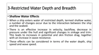
Other Type of Resistances Increased Resistance in Shallow Water Resistance caused by shallow water effect Flow velocities under the hull increases in shallow water. Increase of frictional resistance due to the velocities Pressure drop, suction, increase of wetted surface area Increases frictional resistance The waves created in shallow water take more energy from the ship than they do in deep water for the same speed. Increases wave making resistance
Operating to Minimize Resistance Keep the Hull Clean Operate at a Prudent Speed Keep speed below hump speed to optimize economy
Tow Tank Modeling So far we ve discussed what resistance is and how it can quantified using: RT by measuring the actual resistance force CT dimensionless coefficients that can be used to compare resistance between dissimilar hull shapes and sizes We can now measure the resistance in a hull and use the data to designing a ship s power plant Using the resistance data, an effective power plant can be designed Taking into account the relationship between: Effective Horsepower, EHP Shaft Horsepower, SHP
Tow Tank Modeling Resistance and power are related: On Equation Sheet (Ch. 7) Resistance can be measured in two ways: 1. Computer modeling Can be very difficult to mathematically model viscous flow in 3 dimensions 2. Tow Tank testing Producing a geometrically and dynamically similar model to test Relate model performance to expected actual ship performance
Tow Tank Modeling Tow Tank testing is the obvious way to go! But to do so, your model ship must meet some criteria: Geometric Similarity The dimensions of the model and ship must be scaled exactly The Scale Factor is called (lambda) Length: ? = ?? ?? Area: ?2= ?? ??2 Volume ?3= ?? ??3 where: M = Model S = Ship Note: a minor error in any length measurement will be cubed in volume scaling! ??(??) ??(??2) On Equation Sheet (Ch. 7) ??(??3)
Example The USS Monitor was 197 ft long and 40 ft across the beam and was able to maintain a maximum speed of 6 kts. You would like to create a model for testing that is 5 ft long. How fast should the model be towed to represent the actual ship s max speed? = LS/LM = 197 ft /5 ft = 39.4 VM = VS -1/2 VM = 6 kts (1.688 ft/sec-kts) x 39.4-1/2 On Equation Sheet (Ch. 1) VM = 10.128 ft/s x .1593 VM = 1.6134 ft/s On Equation Sheet (Ch. 7)


")
")

")
")

")
")
")
")
")
")
")

")