Understanding Receivers and Noise in Radio Astronomy
Discover the challenges faced in radio astronomy due to noise, with the signal often indistinguishable from background noise. Learn about receiver sensitivity issues, minimizing thermal noise, and mitigating atmospheric effects to improve observation quality. Explore the essential elements of telescope receiver systems and the importance of technology in detecting weak signals from the sky.
Download Presentation

Please find below an Image/Link to download the presentation.
The content on the website is provided AS IS for your information and personal use only. It may not be sold, licensed, or shared on other websites without obtaining consent from the author. Download presentation by click this link. If you encounter any issues during the download, it is possible that the publisher has removed the file from their server.
E N D
Presentation Transcript
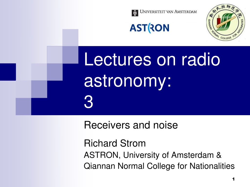
Lectures on radio astronomy: 3 Receivers and noise Richard Strom ASTRON, University of Amsterdam & Qiannan Normal College for Nationalities 1
Signal we want (from sky) has unfortunate properties: Its statistical characteristics are just those of noise, indistinguishable from other background noise (from the ground, atmosphere, receiver, etc.) It is usually much weaker than other sources (ground, receiver, etc.) Detecting it requires top technology, and a lot of clever tricks also 2
Noise from solar pulse (spectrum) 4
Telescope receiver system: essential elements Sensitivity Tunable frequency Total (instantaneous) bandwidth Frequency channels/resolution Stability of output signal Dynamic range Also useful are simplicity, ease of operation & maintenance, flexibility 5
Receiver sensitivity issues Choose low-noise components nowadays often FET/HEMTs; can be cooled (even to < 4 K) for less thermal noise Minimize effect of lossy components (cables, connectors, atmosphere, filters): loss of -0.1 dB (= 2.3%, or factor 0.977) will add 2.3% 290 K = 7 K to system noise. So, short cables, cooled filters, etc. before amplifier 6
Troposphere significant for < 10 cm; solutions? Get above troposphere (mm telescopes are on mountains); go into space? Observe at high elevation. Atmospheric effect depends on thickness. Looking at zenith angle z > 0 (z = 0 is straight up) increases thickness (and effect) by sec z Observe from dry site effect is mainly due to water vapor in troposphere Observe short when weather s good 7
This shows Tsys as a function of elevation (atmosphere) 8
Telescopes like 15 m SEST: high (2500 m) and dry site 9
Frequency requirements of radio astronomy receivers Should be able to (quickly) tune to any frequency band Within that band, may want to have many channels over some range (line observations) For continuum, maximum possible bandwidth gives greatest sensitivity (includes more signal) 10
Basic modern receiver (VLBA) Cryogenic systems are housed in a cryostat, often with an inner cold level (He) at 4-20 K Even if not cooled, the electronics should be in a temperature-stable box (held constant to ~ 1 C)
Structure of a typical superheterodyne receiver
Receiver basic blocks Now let s look at the main elements in more detail; they are: Horn/polarizer LNA Filter + amplifier Calibration system Mixer LO system (not shown in detail)
Mixer used for frequency conversion of signal: Frf Fif 14
Mathematics of the super- heterodyne system Basic idea is to multiply together signals of two different frequencies From the trigonometric identity: sinf1 sinf2 = cos(f1 f2) cos(f1 + f2) The result of multiplying two sinusoidal signals together is signals at the sum and difference frequencies; the latter gives us an intermediate frequency: fIF = |fsky fLO| 15
Features of the superheterodyne system A local oscillator (LO) signal is mixed with sky signal: converts sky to intermediate frequency (fIF) In general, 2 sky frequencies (upper and lower sidebands) are produced; may not be desirable, so filter one out if not wanted The same IF system can be used for different antenna signals 16
Scanning filter receiver (ancient) Use bandwidth of desired resolution Tune over expected frequency range OK, but inefficient 17
Digital autocorrelation spectrometer 19
FT 20
Two related issues of tf The Crab pulsar emits giant pulses of S > 1000 Jy lasting 1 ns Since (1 ns)-1 = 1 GHz such pulses can only be resolved with a receiver BW 1 GHz And the emission itself has to be at least 1 GHz wide Giant pulses from PSR 0531+21 21
A mystery of first years in Westerbork (WSRT) WSRT had twelve 25 m dishes, all the same All cables were of equal length, carefully measured But there were differences of several meters in delay BW = 4 MHz; (4 MHz)-1 = 25 sec; c = 75 m FE BWs likely differ a bit 22
Available noise power R at T R The signal from resistor R, at temperature T, is filtered and limited to a bandwidth, B (= f2 f1) The resulting signal in resistor R has a power, Pn = BkT 24
In a similar way, we can determine equivalent noise R In a similar setup, we filter the signal from an unknown source From the power in resistor R , we can calculate: Ts = Pn/kB 25
What is the equivalent noise of the amplifier? 26
HFET (HEMT) Low Noise Amplifier (LNA) 28
What is the noise contribution of amplifiers in series? 29
Example of receiver temperature calculation Receiver system, 3 amplifiers: 1, 2 & 3 T1 = 50 K, G1 = 20 dB (= 100 ) T2 = 300 K, G2 = 10 dB (= 10 ) T3 = 500 K TN = 50 K + 300 K/100 + 500 K/(10 100) = 50 K + 3 K + 0.5 K = 53.5 K (divide each Tn by product of all gains before it) So we see, 1st amplifier has main effect. 30
Noise contribution of input loss 31
The lesson, when designing a receiver, is... Put a low noise amplifier (LNA) with high gain (G 20 dB) at front Avoid any losses before the LNA (so, keep cables short, or use waveguide; avoid filters if possible, or cool them; keep atmospheric loss low choose a good site) Noise from lossy element after LNA gets divided by LNA gain (G1) 32
Final noise determined by TN, bandwidth, duration 33
Here is an example of time integration in practice Observation of pulse from ms pulsar PSR1937+21 Integration time increases by 2 each step from bottom See pulse better, lose some detail [frequency smoothing gives similar result] 34
Having sensitivity is useless if stability is poor Amplifiers with high gain tend to be less stable To keep output stable, often add feed- back loop: automatic gain control (AGC) Physicist Robert Dicke invented technique: switch to reference noise source, to monitor receiver. 35
Example of a simple Dicke switch radio telescope Generate switching frequency, faster than system drift Demodulate at same frequency after detection Disadvantage is not all time spent on source: lose some observing time 36
Avoid loss of observing time with two receivers Always observing sky and reference At end, average two difference signals Always need stable reference This system costs more (2 channels) 37
Dickes technique widely used, in different ways For example, with two receivers, we can make two beams We can point one beam at source, other on empty sky. Using Dicke s switch, one beam becomes reference can switch out effect of atmosphere. 38
Effelsberg 2.8 cm system (Emerson et al., 1979) 39
What dual-beam measures & example of data (in fog) 40
Observation of strong source 3C84: data & result NEGATIVE 41
Technique can also be used for mapping extended sources For Effelsberg dish (100 m diameter) observing at = 2.8 cm Rayleigh distance: DR D2/ = 1002/0.028 = 360 km Troposphere (where water is) is at 2-3 km altitude, so should be same in both beams 42
Single-beam map of 3C10, showing effects of atmosphere 43
Cas A, beam separation = 8.2 arc: 2 images well separated NEGATIVE 44
Images not always separated: 3C10, 5.5 arc beam distance 45
3C10, final map separates and averages two images 46
Triple-horn system: 3 beams are even better 47
Two final sensitivity issues: polarization and confusion If we only observe with one antenna and receiver, we miss half the signal (for unpolarized sources). Must also have a second antenna with opposite sense of polarization Second antenna must have its own receiver system (so it costs more, but gives better sensitivity by 2) Why is sensitivity better by 2? 48
Antenna with one polarization misses half the signal 49
Horn/polarizer Horn determines the dish illumination (hence dish efficiency), spillover and polarization properties Shown here, hybrid mode prime focus feed designed for high efficiency and low spillover Horn may be mounted on OMT to separate the two polarization channels
Orthomode transducer (OMT) Used to separate two orthogonal polarizations Can be 2 linear or (after phase shift ) 2 circular polarizations Pure linear is easier to realize, but circular is desirable for use in VLBI Examples of OMTs, which can be large, heavy, and difficult to design & build
