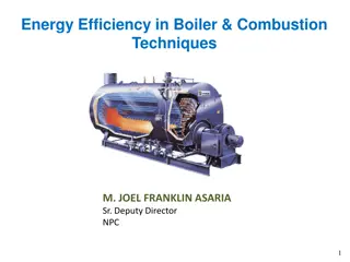
Understanding Energy Efficiency in Boiler Systems
Learn about the importance of energy efficiency in boiler systems, the different types of boilers, boiler components, major losses in boiler efficiency, methods for assessing efficiency, and calculations using the direct method. Exploring topics such as boiler efficiency, water treatment systems, fuel supply systems, and more.
Download Presentation

Please find below an Image/Link to download the presentation.
The content on the website is provided AS IS for your information and personal use only. It may not be sold, licensed, or shared on other websites without obtaining consent from the author. Download presentation by click this link. If you encounter any issues during the download, it is possible that the publisher has removed the file from their server.
E N D
Presentation Transcript
Energy Efficiency in Boiler System Page 1
Boilers Pressure vessel for producing steam or hot water Steam boilers are able to burn fossil fuels like oil, gas, and coal A major portion of energy (fuel) in a facility is accounted for by boiler plant Classified broadly as Fire tube boilers or Water tube boilers Fire Tube Water Tube Page 2
Boiler System Water treatment system Feed water system Steam System Blow down system Fuel supply system Air Supply system Flue gas system Page 3
Boiler Efficiency Major losses in boiler Heat loss due to dry fluegas Heat loss due to steam in fuelgas Heat loss due to moisture infuel BOILER Fuel Heat loss due to moisture inair Heat loss due to unburnts in residue Heat loss due to radiation &other unaccounted loss Heat in Steam Page 4
Boiler Efficiency Boiler efficiency is measure of how effectively heat is transferred from combustion gases to water or steam Two methods for assessing boiler efficiency: Direct method Indirect method Stack Gas FUELINPUT STEAM OUTPUT Convection & Radiation Blow Down Ash and Un-burnt parts of Fuel inAsh Page 5
Efficiency Using Direct Method Boiler efficiency = Heat absorbed in steam Heat supplied by fuel Heat supplied by the fuel depends on the product of quantity of the fuel burnt (kg/hr) and its calorific value (kcal/kg or kJ/kg) = Flow rate of steam x (Enthalpy of steam Enthalpy of feed water) x 100 Quantity of fuel fired x Calorific value of fuel Evaporation Ratio (Steam-Fuel consumption ratio) = Feed water consumption (kg/hr) Fuel consumption (kg/hr) Page 6
Efficiency Calculation by Direct Method Type of boiler: Coal fired Boiler Heat input data Qty of coal consumed :1.8 TPH GCV of coal :3200K.Cal/kg Heat output data Qty of steam gen : 8 TPH Steam pr/temp:10 kg/cm2(g)/1800C Enthalpy of steam(sat) at 10 kg/cm2(g) pressure:665 KCal/kg Feed water temperature : 850 C Enthalpy of feed water : 85 KCal/kg Find out the Find efficiency ? Find out the Evaporation Ratio? Page 7
Boiler efficiency (): = Q x (H h) x 100 Where Q = Quantity of steam generated per hour (kg/hr) H = Enthalpy of saturated steam (kcal/kg) h = Enthalpy of feed water (kcal/kg) (q x GCV) q = Quantity of fuel used per hour (kg/hr) GCV = Gross calorific value of the fuel (kcal/kg) Boiler efficiency ( )= 8 TPH x1000Kg/Tx (665 85) x 100 1.8 TPH x 1000Kg/T x 3200 = 80.0% Evaporation Ratio = 8 Tonne of steam/1.8 Ton of coal = 4.4 Page 8
Typical Evaporation Ratios Type of fuel Typical Evaporation Ratio Fuel oil Solid fuel Gaseous fuel ~ 13 14 kg steam/kg fuel oil ~ 4 5 kg steam/kg solid fuel ~ 13 kg steam/Nm3 gaseous fuel Page 9
Efficiency Using Indirect Method Reference Standard for Boiler Testing at Site British Standard, BS 845:1987 USA Standard ASME PTC-4-1 Power Test Code Steam Generating Units Indirect method is also called the heat loss method Efficiency is calculated by subtracting the heat loss fractions from 100 Page 10
Efficiency Using Indirect Method Efficiency of boiler ( ) = 100 - (i + ii + iii + iv + v + vi + vii) The various losses occurring in a boiler are as follows: i. ii. Evaporation of water formed due to hydrogen (H2) in fuel iii. Evaporation of moisture in fuel iv. Moisture present in combustion air v. Unburnt fuel in fly ash vi. Unburnt fuel in bottom ash vii. Radiation and other unaccounted losses Dry flue gas Page 11
Efficiency Using Indirect Method Page 12
Efficiency Using Indirect Method Page 13
Efficiency Using Indirect Method Page 14
Efficiency Using Indirect Method Page 15
Efficiency Using Indirect Method Page 16
Summary of Heat Balance for the Boiler Using Furnace Oil kCal / kg of furnace oil Input / Output Parameter % Loss Heat Input = 10000 100 Losses in boiler : 1. Dry flue gas, L1 = 786 7.86 2. Loss due to hydrogen in fuel, L2 = 708 7.08 3. Loss due to Moisture in fuel, L3 = 3.3 0.033 4. Loss due to Moisture in air, L4 = 38 0.38 5. Partial combustion of C to CO, L5 = 0 0 6. Surface heat losses, L6 = 38 0.38 Boiler Efficiency = 100 - (L1 + L2 + L3 + L4 + L6) = 84.27 % Page 17
Boiler System Energy Savings Page 18
Boiler System Energy Savings Flue Gas Loss High excess air high flue gas loss Insufficient air-incomplete combustion and soot built-up Excess air norm- 10-15% (2-3% O2) Carbon dioxide (%) Type of Fuel Oxygen (%) Carbon monoxide (ppm) Excess air (%) Liquid fuel 3 4 12 14 <200 10 20 Gas fuel 1 2 9 10 <200 10 20 Solid fuel 12 13 12 13 <200 50 70 Page 19
Reduce Stack Temperature Stack indicates potential for recovery of waste heat. It also indicate the scaling of heat transfer/recovery equipment and hence the urgency of taking an early shut down for water / flue side cleaning. temperatures greater than 200 C 22o C reduction in flue gas temperature increases boiler efficiency by 1% Page 20
Boiler System Energy Savings Waste Heat Recovery from Flue Gas Temperatures of flue gas: 180 -250oC About 10 20% Flue gas heat loss Waste heat recovery heat exchanger (Economizer or Recuperator) Potential temperature margin should be at least 25 30oC flue gas Page 21
Feed Water Preheating using Economizer For an older shell boiler, with a flue temperature of 260oC, an economizer could be used to reduce it to 200oC, Increase in overall thermal efficiency would be in the order of 3%. Condensing economizer(N.Gas) gas reduction up to 65oC 6oC raise in feed water temperature, by economiser/condensate recovery, corresponds to a 1% saving in fuel consumption gas exit Flue Page 22
Combustion Air Preheating Combustion alternative to feedwater heating. air preheating is an In order to improve thermal efficiency by 1%, the combustion air temperature must be raised by 20 oC. Page 23
Incomplete Combustion Incomplete combustion can arise from a shortage of air or surplus of fuel or poor distribution of fuel. In the case of oil and gas fired systems, CO or smoke with normal or high excess air indicates burner system problems. Example: Poor mixing of fuel and air at the burner. Poor oil fires can result from improper viscosity, worn tips, carbonization on tips and deterioration of diffusers. With coal firing: Loss occurs as grit carry-over or carbon- in-ash (2% loss). Page 24
Control excess air for every 1% reduction in excess air ,0.6% rise in efficiency TABLE 2.5 EXCESS AIR LEVELS FOR DIFFERENT FUELS Fuel Type of Furnace or Burners Excess Air (% by wt) 15-20 Pulverised coal Completely water-cooled furnace for slag- tap or dry-ash removal Partially water-cooled furnace for dry-ash removal Spreader stoker Water-cooler vibrating-grate stokers Chain-grate and traveling-grate stokers Underfeed stoker Oil burners, register type Multi-fuel burners and flat-flame High pressure burner Dutch over (10-23% through grates) and Hofft type All furnaces Recovery furnaces for draft and soda- pulping processes 15-40 Coal 30-60 30-60 15-50 20-50 15-20 20-30 5-7 20-25 Fuel oil Natural gas Wood Bagasse Black liquor 25-35 30-40 Page 25
Boiler System Energy Savings Oxygen Trim System Monitors Oxygen level in flue gas and automatically adjusts the air- to-fuel ratio combustion efficiency for maximum Oxygen level and excess air in flue gas kept optimum at all loads Reduces energy consumption by 1.5 2.0% Payback period less than 3 years Page 26
Boiler System Energy Savings Automatic Damper Control High draft High excess air Damper between boiler and stack automatically controls the draft by opening or closing the damper depending on the feedback from O2 (excess air) level Page 27
Boiler System Energy Savings Low Excess Air Burner Older burners require more excess air for combustion Low excess air burners not only operate with low excess air but improve combustion efficiency as well Page 28
Boiler System Energy Savings Blowdown Blowdown is a discharge of water at steam temperature to remove sludge and solids from boiler Conductivity, silica, chlorides concentrations, alkalinity indicate presence of dissolved salts and other contaminants in boiler water Blowdown water has to be replaced by an equivalent amount of feed water Boiler blowdown (%) = Feed water TDS x % Makeup water Maximum Permissible TDS in Boiler water Blowdown rate is set proportional to makeup water flow or automated (probe provides feedback to a controller operating a modulating blowdown valve) Page 29
Blowdown Heat Recovery Efficiency Improvement - Up to 2 percentage points. The amount of blowdown should be minimized by following a good water treatment program, but installing a heat exchanger in the blowdown line allows this waste heat to be used in preheating makeup and feedwater. Heat recovery is most suitable for continuous blowdown which in turn provides the best water treatment program. operations Page 30
Boiler System Energy Savings Automatic Blowdown Control and Heat Recovery System Heat recovery system recommended for continuous blowdown with atleast 5% makeup water Fresh makeup water is heated Flash steam can also be recovered as low- pressure steam or condensed back for reuse as boiler feed water Page 31
Boiler System Energy Savings Fouling or scaling- Water side Act as insulators and reduces heat transfer resulting in higher flue gas temperature Higher flue gas temperatures at constant steam demand and excess air level Water treatment has to be improved- Improve softening and lower total dissolved solids (TDS) through chemicals into boiler feed water and adopting proper boiler blowdown Soot- Fire side Act as insulators and reduce heat transfer higher flue gas temperature Burner is defective or air supply is insufficient. Surfaces should be cleaned of soot periodically Repair the burner and fine- tune the combustion system. resulting in water maintaining injecting Page 32
Fouling and Scaling Scale formation Soot formation Page 33
Reduction of Boiler Steam Pressure Lower steam pressure gives a lower saturated steam temperature and without stack heat recovery, a similar reduction in the temperature of the flue gas temperature results. Potential 1 to 2% improvement. Steam is generated at pressures normally dictated by the highest pressure / temperature requirements for a particular process. In some cases, the process does not operate all the time, and there are periods when the boiler pressure could be reduced. Adverse effects, such as an increase in water carryover from the boiler owing to pressure reduction, may negate any potential saving. Pressure should be reduced in stages, and no more than a 20 percent reduction should be considered. Page 34
Boiler System Energy Savings Steam Generation Pressure Reduction High pressure steam-high fuel combustion Boiler steam pressure should be based on the temperature required in the heating process Not on steam pressure that can be generated in boiler Reset steam pressure in boiler to match with the actual steam load requirements to save energy Recommended steam pressure = Maximum pressure required + Pressure drop in the system Page 35
Boiler System Energy Savings Benefits of Low-pressure Steam Latent heat for condensing steam is higher at lower pressure Steam dryness ratio will increase resulting in increase in energy in steam Steam loss from pipes will be lower at lower steam pressure Heat loss at boiler surface and steam distribution system will be less at lower steam pressure Blowdown loss will be less at lower steam pressure Fuel consumption will be lower for the same amount of steam generation Page 36
Variable Speed Control for Fans, Blowers and Pumps Generally, combustion air control is effected by throttling dampers fitted at forced and induced draft fans. Though dampers are simple means of control, they lack accuracy, giving poor control characteristics at the top and bottom of the operating range. If the load characteristic of the boiler is variable, the possibility of replacing the dampers by a VSD should be evaluated. Page 37
Boiler System Energy Savings Retrofitting Boiler with VFD Boiler Fan at Constant Speed Boiler Fan at VFD Best for boiler operating at constant steam load For part load --damper control air flow to match with steam load Damper create resistance in air flow-Fan power increases Best for boiler operating at varying steam load or low load for longer time Fan power (air flow rate)3 Page 38
Effect of Boiler Loading on Efficiency As the load falls, so does the value of the mass flow rate of the flue gases through the tubes. This reduction in flow rate for the same heat transfer area, reduced the exit flue gas temperatures by a small extent, reducing the sensible heat loss. Below half load, most combustion appliances need more excess air to burn the fuel completely and increases the sensible heat loss. Operation of boiler below 25% should be avoided Optimum efficiency occurs at 65-85% of full loads Page 39
Boiler System Energy Savings Switching Fuels Switch fuel based on price Saves on energy cost- not energy consumption Oil to Biomass Page 40
Boiler System Energy Savings Feed Water Tank Insulation Feed water tank is a reservoir of condensate and fresh makeup water for boilers Feed water is normally hot due to returned condensate recovery of heat from other sources Uninsulated feed water tank and uncovered (at top) losses heat from sides as well as top in form of evaporation and Page 41
Boiler Replacement if the existing boiler is : Old and inefficient, not capable of firing cheaper substitution fuel, over or under-sized for present requirements, not designed for ideal loading conditions replacement explored. Since boiler plants traditionally have a useful life of well over 25 years, replacement must be carefully studied. option should be Page 42
Thermic Fluid Heater Page 43
Energy Auditing Approach Data and Information Collect boiler details: type, rated steam pressure, temperature, and steam capacity. Collect feed water pump details: type, no. of stages, flow, and pressure. Record allowable TDS in boiler. Collect FD/ID fan flow, pressure, motor rating, kW. Collect burner details: type, rated temperature, pressure, turndown ratio. Collect supply and return thermic fluid temperature. Assess thermic fluid loads (temperature, flow). Page 44
Energy Auditing Approach Instruments and Measurements Flue gas analyzer Thermocouple Contact thermometer Hygrometer Page 45
Energy Auditing Approach Field Audit Examine the boiler/thermic fluid log book. Review operating steam/thermic fluid pressure. Review operating steam temperatures. Review steam production records. Measure steam/thermic fluid flows through meters. Steam flow can be indirectly through feed water meter or from level measurements in overhead tank. Review fuel consumption records and check fuel (oil) consumption by measuring difference in fuel oil tank level. Measure gas measurement through gas meter. Review make-up water records. temperature and thermic fluid Page 46
Energy Auditing Approach Field Audit Check condensate return, quantity, and temperature. Measure feed water temperature. Measure O2, CO2 percent in exhaust flue gas, CO level in ppm. Measure oil pre-heat temperature and pressure. Review Allowable TDS in boiler and TDS in blowdown. Measure O2 level before and after heat recovery equipment like economizer, air pre-heater. Check insulation of feed water tank (measure surface temperature and calculate heat losses). Prepare schematic of water treatment system. Review feed water and make-up water testing procedures. Page 47
Energy Auditing Approach Analysis Assess steam-fuel ratio (Evaporation Ratio). Assess efficiency by direct method/indirect method. Compare excess air levels against desirable levels. Check whether oil pre-heating is adequate. Check condition of (burner, coal grate). Review flue gas temperature trend over last few months. Conduct mass and energy balance of boiler system including blowdown. Evaluate scope for waste heat recovery. fuel firing equipment Page 48
ENCON Opportunities Thermic Fluid Heaters Operational and Housekeeping Measures Optimize excess air. Higher excess air increases flue gas quantity and stack loss. It also reduces flame temperature, radiation heat transfer, and heat transfer to heating surfaces. Lower excess air may result in incomplete combustion which leads to formation of CO in flue gas. The maximum permissible CO level is 1%. Reduce thermic fluid outlet temperature If temperature difference between thermic fluid outlet temperature and the medium being heated is quite high, it may be possible to reduce the outlet temperature after conducting field trials. This will also reduce stack loss as well as radiation loss from the thermic fluid heater circuit. Page 49
ENCON Opportunities Thermic Fluid Heaters Low Cost Measures Optimize burner nozzle size. If the thermic fluid heater operates at low fire for long period in a cycle rather than high fire, the efficiency of heater will be lower. In such cases, it is better to improve overall energy efficiency by changing the nozzle size so that heater output matches with the system load. Optimize the flow of thermal oil for multiple process heating applications: when a single thermic fluid heater is used to provide heat to many processes or systems, it is important to supply correct quantity of thermal oil to each process by controlling the mass flow rate of thermic fluid using auto-control valves. Upgrading the condition of insulation of thermic fluid heater and distribution pipelines. Check for and remove redundant lines and valves in distribution lines to reduce distribution losses. Page 50


