Introduction of Electrical Transmission Braking Systems Workshop
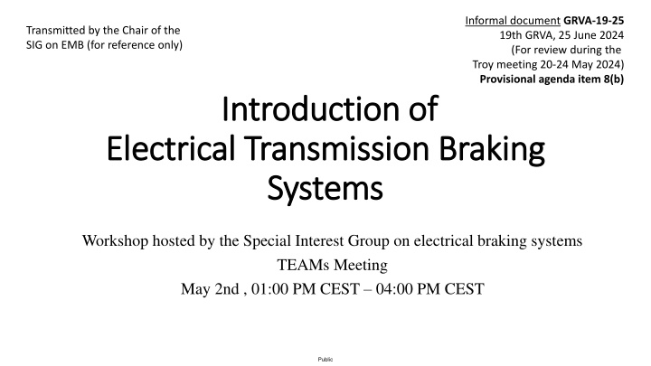
The Special Interest Group on electrical braking systems is hosting a workshop to discuss the drafting principles, terminology, and indicators related to electrical transmission braking systems. The workshop aims to identify safety critical elements, propose amendments to UN Regulations, and make recommendations for applying electrical system safety principles to various regulations. Key topics include energy supply, brake transmission architectures, and essential principles governing braking systems employing stored energy.
Download Presentation

Please find below an Image/Link to download the presentation.
The content on the website is provided AS IS for your information and personal use only. It may not be sold, licensed, or shared on other websites without obtaining consent from the author.If you encounter any issues during the download, it is possible that the publisher has removed the file from their server.
You are allowed to download the files provided on this website for personal or commercial use, subject to the condition that they are used lawfully. All files are the property of their respective owners.
The content on the website is provided AS IS for your information and personal use only. It may not be sold, licensed, or shared on other websites without obtaining consent from the author.
E N D
Presentation Transcript
Informal document GRVA-19-25 19th GRVA, 25 June 2024 (For review during the Troy meeting 20-24 May 2024) Provisional agenda item 8(b) Transmitted by the Chair of the SIG on EMB (for reference only) Introduction of Introduction of Electrical Transmission Braking Electrical Transmission Braking Systems Systems Workshop hosted by the Special Interest Group on electrical braking systems TEAMs Meeting May 2nd , 01:00 PM CEST 04:00 PM CEST Public
Table of Contents Table of Contents 1. EBSIG s Terms of Reference (TOR s) Mr. B. Frost (Chair SIG EMB) 2. 3. 4. EBSIG s Drafting principles Specimen architectures Brake circuit isolation Mr. B. Frost (Chair SIG EMB) Mr. P. Teyssier ( OICA) / Mr. N. Syed (CLEPA) Mr. S. Schilling (CLEPA) 5. 6. 7. Periodical Technical Inspection (PTI) Terminology Principles to manage energy Mr. P. Teyssier (OICA) Mr. N. Syed (CLEPA) Mr. H. Hunold / Mr. S. Schilling (CLEPA) 8. 9. 10. Indicators EMS Annex 7 (R 13) , Annex 4 ( 13-H) Mr. S. Schilling (CLEPA) Mr. V. Heim / Mr. P. Teyssier (OICA) Mr. P. Teyssier (OICA)/ Mr. C. ADAM (CLEPA) 11. Auxiliaries Mr. V. Kenneweg (OICA) 18/05/2024 Electrical Braking Special Interest Group 2 Public
1. EBSIG 1. EBSIG s Terms of Reference s Terms of Reference(GRVA-18-54) A. Energy supply and brake transmission architectures. 1. Identify design principles for the energy supply. 2. Identify the brake transmission arrangements that may be recognised by UN Regulations Nos. 13 and 13-H. 3. Develop recommendations for the methodology of measuring/monitoring the value of energy available in a reserve of energy suitable for use in identifying critical energy thresholds. 4. Identify the safety critical elements of electromechanical braking systems that will require monitoring for fault/failure and the generation of warning signals. B. Based upon understanding from the above, and building upon the content of the GRVA Informal Document GRVA-15-17: 1. Develop proposals to amend UN Regulation No. 13, 2. Develop proposals to amend UN Regulation No. 13-H, and 3. Make recommendations regarding the application of the electrical system safety principles with respect to other UN Regulations, esp. UN Regulation No. 79. 18/05/2024 Electrical Braking Special Interest Group 3 Public
2. EBSIG 2. EBSIG s drafting principles s drafting principles (GRVA-16-07) The essential principles of the regulations are that a braking system employing stored energy: 1. May have a vacuum, hydraulic, pneumatic, electric, or mixed medium transmission. 2. The transmission must comprise at least two independent braking circuits each acting on a minimum of two wheels. 3. Each of those circuits must have its own independent energy reserve. 4. The value of each reserve must be monitored, and a warning system must be provided to alert the driver if the value falls below a prescribed level. 5. At all times that the vehicle is able to be driven (or be in motion), and there are no faults present in the system, the total value of the energy reserves has to be sufficient to satisfy the performance requirements of regulations. 6. When isolated from its supply, the total energy reserve must allow a defined number of full brake applications and still be sufficient to ensure secondary braking at the end. 7. The energy reserve of each circuit must be maintained at a level that can ensure secondary brake performance should a fault/failure occur in the other circuit. 18/05/2024 Electrical Braking Special Interest Group 4 Public
3. Specimen architectures 3. Specimen architectures ETBS versus EBS 2.52. Electronically controlled Braking System (EBS) means a service braking system where the control is generating an electrical signal in the control transmission and electrical output signals to devices which generate actuating forces produced from stored or generated pneumatic energy. This new definition is specific to R13 and covers existing typical layouts on HCVs (since the mid-90 s): the so called Electronic Braking System (EBS) . The aim is to avoid any confusion between EBS and ETBS. EBS is addressed with special additional requirements of section 5.2.1.27., while ETBS is addressed in new section 5.2.1.35. EBS ETBS Control transmission Electrical Transmission Braking System (ETBS) means a braking system of a power- driven vehicle where the service braking force, and transmission, depend exclusively on the use, controlled by the driver, of energy provided from electrical storage devices. 2.53. Electrical * Electrical Energy transmission Pneumatic Electrical * Existing systems all have a pneumatic backup 18/05/2024 Electrical Braking Special Interest Group 5 Public
3. Specimen architectures 3. Specimen architectures Caution (about the layouts) The following layouts are only indicative diagrams, not actual implementations. They do not aim to show an exhaustive view of all possibilities. The principles of the different layouts could be mixed and give new layouts. 18/05/2024 Electrical Braking Special Interest Group 6 Public
3. Specimen architectures 3. Specimen architectures Electronically Controlled Braking System Electronically Controlled Braking System - - Typical HCV EBS layout (R13) Typical HCV EBS layout (R13) Energy Source air Air tank circuit 1 Air Compressor Circuit 1 Brake Valve 2 Brake Valve 1 ICE Mechanical drive Circuit 2 Air Tank circuit 2 Alternator Electrical signal Brake Controller 3 1 2 air Control transmission Battery 24V Energy transmission Energy supply 18/05/2024 Electrical Braking Special Interest Group 7 Public
3. Specimen architectures 3. Specimen architectures ETBS ETBS - - Layout 1 Layout 1 - - Specific battery for braking Specific battery for braking Energy Source Specific battery for braking ESD 1 KL 30.1 Alternator Circuit 1 Brake Controller 2 Brake Controller 1 ICE Mechanical drive Battery 24 V ESD 2 Circuit 2 Auxiliary equipment 1 2 Highlights: The energy in the Electrical Storage Devices (ESD) can only be used by the braking system. This layout has an energy source (the alternator). The energy source is part of the electrical supply. Control transmission Energy transmission Energy supply Public
3. Specimen architectures 3. Specimen architectures ETBS ETBS - - Layout 2 Layout 2 - - Multipurpose battery for braking and auxiliaries Multipurpose battery for braking and auxiliaries battery for braking and auxiliaries ESD 1 No energy Source KL 30.1 DC /DC Circuit 1 Traction Battery (HV) Brake Controller 2 Brake Controller 1 ESD 2 Circuit 2 Auxiliary equipment 1 2 Highlights: The energy in the Electrical Storage Devices (ESD) can be used by the braking system and by auxiliary equipment. This layout has no energy source (a traction battery is not a source). Control transmission Energy transmission Energy supply Public
3. Specimen architectures 3. Specimen architectures ETBS ETBS - - Layout 3 Layout 3 - - Traction battery used as an electrical storage device Traction battery used as an electrical storage device battery for braking and auxiliaries ESD 1 No energy Source Circuit 1 DC /DC Circuit 1 Traction Battery (HV) Brake Controller 2 Brake Controller 1 Circuit 2 Circuit 2 DC/DC ESD 2 Auxiliary equipment Other equipment 1 Steering System 2 Highlights: The traction battery is both the electrical supply of circuit 1 and the electrical storage device of circuit 2 (which has no supply). Another energy medium than electricity may be used to power the brakes, e.g. an electro-hydraulic converter could be used to power hydraulic brakes. Such a layout remains an ETBS since the reserves remains electrical storage devices. This possibility is also valid for the other layouts. Control transmission Energy transmission Energy supply 10 Public
4. Brake circuit isolation 4. Brake circuit isolation Different technical solutions in dependance of the architecture Different technical solutions in dependance of the architecture Architecture Protection Element Electronically Controlled Braking System - Typical HCV EBS layout (R13) Circuit Protection Valve ETBS - Layout 1 - Specific battery for braking Diode ETBS - Layout 2 - Multipurpose battery for braking and auxiliaries Active Separating and Connecting Element (ATV) ETBS - Layout 3 - Traction battery used as an electrical storage device Active Separating and Connecting Element (ATV) 18/05/2024 Electrical Braking Special Interest Group 11 Public
4. Brake circuit isolation 4. Brake circuit isolation Active Separating and Connecting Element (ATV) Active Separating and Connecting Element (ATV) Technological solutions for ATVs exist ATVs are used in production vehicles today They may be standalone components, or integrated into other ECUs (e.g. Zone Controllers) ATVs are an important part of safe vehicle power supply system They can be used to ensure independency in systems other than braking systems 18/05/2024 Electrical Braking Special Interest Group 12 Public
5. 5. Periodical Periodical Technical Technical Inspection Inspection (PTI) (PTI) Procedure to check that the means of detection to trigger the warning signals are operational. Reference braking force: Reference brake values extended from pneumatic systems, therefore applicable to more vehicle categories. First time that reference braking forces are introduced in R13H (alignment on R13). Must be possible to evaluate the relationship between the brake demand and the measured braking force on a roller brake tester. The manufacturer must describe the method by which this can be realized. Challenge: Application of reference braking values for ETBS systems is not standardized (e.g. brake demand value could be as a percent value, a voltage, brake pedal force or stroke, pressure). ETBS is a technology in its infancy; being too prescriptive at this stage could limit the possibilities for development. PTI requirements could be reviewed in the medium term, based upon market experience. 18/05/2024 Electrical Braking Special Interest Group 13 Public
Coffee Break Coffee Break Public
6. Terminology 6. Terminology 6.1. Electrical Storage Device "Electrical storage device" means a device, or combination of individual devices, each capable of storing an electrical charge and of providing electrical power to the braking system transmission. Electrical storage devices which are connected in series and/or parallel for the purpose of supplying a single braking circuit, shall be considered as one electrical storage device within this Regulation. - + - + - + - + - + - + - + - + A combination of devices in series = one electrical storage device. A combination of devices in series and parallel = one electrical storage device. - + A combination of devices in parallel = one electrical storage device. - + 18/05/2024 Electrical Braking Special Interest Group 15 Public
6. Terminology 6. Terminology 6.2. Electrical Storage Device The state of an electrical storage device means its ability to provide power (W) and quantity of energy (Wh) at the time. transmission transmission This is the useful extractable power and energy (which is available to the transmission) based on the condition at the time. - + - + This may vary with battery temperature. This will vary during discharge and re-charge. The performance of an electrical storage device means its ability to provide power (W) and quantity of energy (Wh) when fully charged. This is the useful extractable power and energy (which is available to the transmission) when fully charged. This may reduce over time through use. transmission transmission - + - + The effect of ageing is quantifying the irreversible degradation of the performance of an electrical storage device, due to e.g., the effects of time, use, and environmental exposure. 18/05/2024 Electrical Braking Special Interest Group 16 Public
Terminology Terminology 6.3. Energy Source and Electrical Supply - + - DC - - Batt DC + + + Alternator Battery / Capacitor (similar to an air tank) DC/DC (similar to compressor) (similar to a pressure regulator) "Energy device that both generates and provides energy required for the braking system. source" means a Is not generating, but only releasing energy Is not generating, but only processing (high voltage) electrical energy to (low voltage) electrical Is a source because it generates electrical energy stored "Electrical supply" means a device (e.g. battery, REESS, generator, fuel-cell or a combination of these components) electrical power to the braking system's electrical device(s). In most layouts it is a storage device. However, it can be part of a supply (e.g. Traction battery that supplies the braking system s storage device). Is part of the supply As part of the supply that supplies storage electrical 18/05/2024 Electrical Braking Special Interest Group 17 Public
7. 7. Principles to manage energy Principles to manage energy The energy medium is the fundamental difference between an Electric Transmission Braking Systems (ETBS) and current technology (electrical energy versus compressed air). In case of ETBS, the energy, that can be provided to the braking system must be predicted whereas in a pneumatic braking system the available energy is measurable. Unlike pneumatic pressure, the electric energy cannot be directly measured but only be assessed based on monitoring of several physical parameters. The most relevant parameter is not the energy which is stored in an electrical storage device at any time, but rather the energy and the power which is capable of being provided to the electrical load (i.e., the brake). 18/05/2024 Electrical Braking Special Interest Group 18 Public
8. Energy Management System (EMS) 8. Energy Management System (EMS) General tasks how measure and manage electrical energy General tasks how measure and manage electrical energy 1. Measure and/or monitor in real time the energy available in the reserve in all operating conditions and over the lifetime (high/low temperatures, ageing, ). 2. Determine the value of the power and the energy that can be provided to the brake transmission (e.g., the effect of resistance on the flow of energy). 3. Compare that value with the known threshold value required to meet the specific performances required by the regulations. 4. To generate a warning to the driver in real time in accordance with the known threshold value. 18/05/2024 Electrical Braking Special Interest Group 19 Public
8. Energy Management System (EMS) 8. Energy Management System (EMS) Pneumatic Braking System vs. Electrical Transmission Braking System Pneumatic Braking Systems (PBS) the reserve of energy can be measured and monitored at any time directly (by direct means at TA and PTI ) Electrical Transmission Braking System (ETBS) according to para. 2.5.3. (UN R13) and para. 2.34. (UN R13H) the reserve of energy cannot be measured and monitored at any time directly. multiple signals (voltage, current, temperature) are necessary to be observed to measure, monitor, and deduce the output power of the Electrical Storage Device (reference: para 2.48 (UN R13), para. 2.30 (UN R13H)) Electrical Transmission Braking System (ETBS) means a braking system of a power-driven vehicle where the service braking force, and transmission, depend exclusively on the use, controlled by the driver, of energy provided from electrical storage devices. Definition of Energy Management System (EMS) according to para. 2.51. (UN R13) and para. 2.33. (UN R13-H) Energy Management System means, an electrical device(s), being part of, or used by, an electrical transmission braking system, that monitors critical variables that impact on the performance and state of the electrical storage devices (e.g., voltage, temperature, internal resistance, effect of ageing, state of charge, power consumption, charging cycles, etc.) and deduces the actual capability of the devices to fulfil the performance requirements of this Regulation. 18/05/2024 Electrical Braking Special Interest Group 20 Public
8. Energy Management System (EMS) 8. Energy Management System (EMS) (Example: Lead acid battery state detection| basic principle) Voltage Estimator of battery states & parameters Examples of Predictors A Current Indicator 5.2.1.13.2. (UN R13) 5.2.14.4. (UN R13-H) V Model of the battery Temperature - + State of the electrical storage device Adaption of parameters T Determine effect of ageing Warning light 5.2.1.35.6 (UN R13) 5.2.24.6 (UN R13-H) State variables and model parameters as an input for the Predictors Signals to be measured and given as an input for the model of the battery ( voltage ,current, temperature) Warnings and Indicators are continuously triggered Load profiles (number of brake applications) Influences like low temperature, high temperature ,the exchange of electrical storage device, ageing; long-time parking shall be considered and covered. Technological solutions for EMS are available from various suppliers, their reliability is field-proven. EMS shall demonstrate compliance according to 5.2.1.35.8.2. / 5.2.1.35.8.3. (UN R13) respectively 5.2.24.8.2. / 5.2.24.8.3. (UN R13-H) UN-R13-Annex18 and UN-R13H-Annex 8 18/05/2024 Electrical Braking Special Interest Group 21 Public
9. Annex 7 / Annex 4 9. Annex 7 / Annex 4 UN R13 / Annex 7 Part A, compressed Start of Annex7 test at pressure p2 declared by the manufactuer Energy for UN R13 / Annex 7 Part A, compressed- -air braking systems air braking systems Start of assessment of Annex7 test (8+1) Red Warning Signal according to 5.2.1.13.1. (a) Service Braking Secondary Braking 9+n 9+3 9+2 9+1 9 8 7 5 4 3 2 1 6 0 Full stroke actuation 18/05/2024 Electrical Braking Special Interest Group 22 Public
9. Annex 7 / Annex 4 9. Annex 7 / Annex 4 Part D, Part D, 1.2.ff. (ETBS) 1.2.ff. (ETBS) Energy for Yellow Warning Signal according to 5.2.1.35.7. Start of Annex7 test (8+1) Red Warning Signal according to 5.2.1.13.1. (b) Service Braking Secondary Braking 9+n 9+3 9+2 9+1 9 8 7 5 4 3 2 1 6 0 Actuation as defined in Annex 7-part D 1.2.2.3 18/05/2024 Electrical Braking Special Interest Group 23 Public
9. Annex 7 / Annex 4 9. Annex 7 / Annex 4 Part D, Part D, 1.2.ff. (ETBS) 1.2.ff. (ETBS) Energy for Start of Annex7 test (8+1) Yellow Warning Signal according to 5.2.1.35.7. Red Warning Signal according to 5.2.1.13.1. (b) Service Braking Secondary Braking 9+n 9+3 9+2 9+1 9 8 7 5 4 3 2 1 6 0 Actuation as defined in Annex 7-part D 1.2.2.3 18/05/2024 Electrical Braking Special Interest Group 24 Public
9. Annex 7 / Annex 4 9. Annex 7 / Annex 4 Part D, clarification of Annex 7, para. 1.2.3.3.: Each actuation shall cause a demand (aref) on the brake actuators necessary to deliver the maximum possible deceleration designed to be delivered by the system in the Type-0 condition (e.g. cold brakes, Type-0 speed, laden, fully charged electrical storage devices), limited to 8.0m/s . The demand value to the brake actuators may be reduced to a lower value areduced, while not being lower than the prescribed service braking deceleration. In this case, the duration- T of each full stroke actuation shall be increased as per according to the following formula below: .. Part D, clarification of 1.2.3.3. 1.2.3.3. Deceleration (maximum) aref=7m/s Case 1 Control Transm. Energy Transm. Brake Control Unit T=8s aexecuted =7m/s aref=aexecuted =7m/s Deceleration (limited) aref=8m/s Case 2 Control Transm. Energy Transm. Brake Control Unit T=8s aexecuted =8m/s aref=aexecuted =8m/s Deceleration (reduced) areduced=6.43m/s Case 3 areduced_min=6.43m/s areduced_min=5m/s Control Transm. Energy Transm. Brake Control Unit T=8/6.43*8s T=9.95s aref areduced areduced=aexecuted =6.43m/s aexecuted =6.43m/s 18/05/2024 Electrical Braking Special Interest Group 25 Public
9. Annex 7 /Annex 4 9. Annex 7 /Annex 4 Part D, Section 2 ( test of the capacity of the electrical supply) Part D, Section 2 ( test of the capacity of the electrical supply) Type-I test (Annex 4) Dynamic test State of the ESDs Yellow warning 5.2.1.35.x Red warning (5.2.1.13.1.b) Brake Start 1 2 3 4 5 6 7 8 9 10 19 20 21 application Energy provided by the electrical supply to the electrical transmission during Type-I dynamic test (followed by the hot performance test) = Energy provided to the electrical transmission during the Annex 7 static test 80%vmax 0km/h max. 1min Capacity of the electrical supply (Annex 7, Part D, section 2) - Static test State of the ESDs Yellow warning 5.2.1.35.x Red warning (5.2.1.13.1.b) Brake application Start 1 2 3 4 5 6 7 8 9 10 19 20 21 PASS Condition: the state of the ESDs is above the level of 18/05/2024 Electrical Braking Special Interest Group the red warning, and the Pw warning is not activated 26 Public
10. 10. Indicator Indicator The indicator shall provide at least [4] different levels of ageing above the level at which a maintenance of the electrical storage device(s) is recommended. This 5thlevel shall be given before the warning signal required by 5.2.1.35.6. is activated. The different levels above this indication shall be evenly distributed with respect to the performance of the ESD. Performance even performance drop between levels (effect of ageing) >= 8+1 Number of cycles 5.2.1.35.6 (UN R13) 5.2.24.6. (UN R13-H) Change recommended Public
11. Auxiliary Equipment 11. Auxiliary Equipment - Circuit with electrical supply - 2.55./2.35. Auxiliary equipment means, for the purposes of this Regulation, the collective of systems, functions, or components, including those that are essential to the operation of the vehicle, that are supplied with energy from the same energy reserves as the braking system. Relevant situation according to 5.2.1.35.10. (5.2.24.10.): Indicative layout Auxiliary Equipment is supplied from the same ESD as the braking system Failure of the electrical supply that is providing energy to this ESD Requirement Failure of the electrical supply ESD starts depleting t Possible strategies between occurrence of failure and red warning Red Warning acc. to 5.2.1.13.1. (b) in R13 resp. 5.2.14.1. (b) in R13-H *) A) B) C) Switching off auxiliary equipment Automatically bringing the vehicle to standstill A combination of both (first switching off parts of aux. eq., later the standstill) IMPORTANT: The operation of auxiliary equipment required to satisfy the performance requirements of another safety related UN regulation shall not be affected. *) Service brake performance cannot be achieved, or 4+1 actuations are still possible, whichever occures first 18/05/2024 Electrical Braking Special Interest Group 28 Public
11. Auxiliary Equipment 11. Auxiliary Equipment - Circuit w/o electrical supply - 2.55./2.35. Auxiliary equipment means, for the purposes of this Regulation, the collective of systems, functions, or components, including those that are essential to the operation of the vehicle, that are supplied with energy from the same energy reserves as the braking system. Relevant situation according to 5.2.1.35.10. (5.2.24.10.): Indicative layout Auxiliary Equipment is supplied from the same ESD as the braking system a) No electrical supply (e.g. Traction Battery is one ESD) -> non-fault b) Failure that prevents Traction Battery from providing braking system Requirement Normal operation or failure occurs 2a) normal operation / 2b) no provision of braking system t Possible strategies before red warning Red Warning acc. to 5.2.1.13.1. (b) in R13 resp. 5.2.14.1. (b) in R13-H *) A) B) C) Switching off auxiliary equipment Automatically bringing the vehicle to standstill A combination of both (first switching off parts of aux. eq., later the standstill) IMPORTANT: The operation of auxiliary equipment required to satisfy the performance requirements of another safety related UN regulation shall not be affected. *) Service brake performance cannot be achieved, or 4+1 actuations are still possible, whichever occures first 18/05/2024 Electrical Braking Special Interest Group 29 Public
