Understanding 4G Handover in Mobile Networks
Explore the complexities of 4G handover procedures, including eNodeB interactions, X2 handovers, preparation, execution, completion, and more. Learn about the roles of MME, UE, and the core network in ensuring seamless handover experiences for mobile users. Dive into detailed illustrations and descriptions to enhance your understanding of this critical aspect of mobile communication networks.
Download Presentation

Please find below an Image/Link to download the presentation.
The content on the website is provided AS IS for your information and personal use only. It may not be sold, licensed, or shared on other websites without obtaining consent from the author. Download presentation by click this link. If you encounter any issues during the download, it is possible that the publisher has removed the file from their server.
E N D
Presentation Transcript
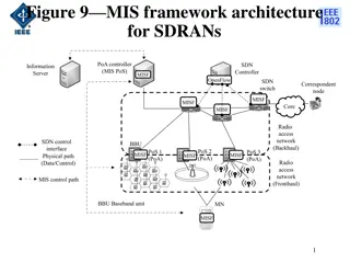
eNodeB Inter-site X2-Handover S1-Handover X2-Handover MME X2 eNodeB S1-Handover X2 eNodeB MME
X2 Handover (1/4) Handover Preparation 6 Resource: Nokia, TTC redraw
1. Source eNB Measurement Control UE 2. UE UE Measurement Report Source eNB 3. Source eNB Measurement Report Handover 4. Source eNB Handover Source eNB X2-AP HANDOVER REQUEST Target eNB Source eNB Old eNB UE X2-AP ID MME MME UE S1-AP ID EPS EPS
5. Target eNB HANDOVER REQUEST ERABs Admission Control Handover 6. Target eNB Handover Target eNB Source eNB HANDOVER REQUEST ACKNOWLEDGE New eNB UE X2-AP ID Old eNB UE X2AP ID EPS 7. Source eNB Target eNB Handover UE Handover Command RRC CONNECTION RECONFIGURATION UE
X2 Handover (2/4) Handover Execution 9 Resource: Nokia, TTC redraw
8. Source eNBPDCP SN STATUS TRANSFER Target eNB Handover Source eNB Target eNB 9. --- 10. --- 11. UE Target eNB RRC CONNECTION RECONFIGURATION COMPLETE Handover Confirm Target eNB UE Handover Target eNB
X2 Handover (3/4) Handover Completion 11 Resource: Nokia, TTC redraw
12. Target eNBMMEPATH SWITCH REQUEST MME Source eNB Target eNB MME UE S1-AP ID eNB UE S1-AP ID EPS Target eNB 13. --- 14. --- 15. --- 16. MME PATH SWITCH REQUEST ACKNOWLEDGE Target eNB Target eNB MME UE S1-AP ID 17. --- 18. Target eNB X2 UE Context Release Source eNB
Handover (source eNB) UE Target RRM RRC RRM MeasurementReport (A3) RRC_MEAS_REPORT_IND (tMeasReportIndMsg) Request RRC to encode HoPrepare msg RRC_HO_INFO_REQ (tRrmInfo) RRC_HO_INFO_CFM (tHoInfoCfm + HoPrepare ASN.1 msg) 1 4 RRCConnectionReconfiguration (Handover) RRC_HO_CMD_REQ (tCrntiMsg + HandoverCommand ASN.1msg) Including DRB PDCP SN status RRC_HO_CMD_CFM (tHoCmdCfm) 5 8 RRC_CON_REL_REQ RRC_CON_REL_CFM
Handover (target eNB) RRC RRM UE Request RRC to decode HoPrepare msg 2 RRC_HO_PREPAR_REQ (tHoPrpReq + HoPrepare ASN.1 msg) RRC_HO_PREPAR_CFM (tHoPrpCfm) Reserve ue radio resource in target eNB and prepare handover command RRC_HO_RSV_REQ (tHandoverCommandMaterial) RRC_HO_RSV_CFM DRB PDCP SN status (tHoRsvCfm + HandoverCommand ASN.1msg) 3 6 RRC_STATUS_IND (tStatusInd) RRCConnectionReconfigurationComplete RRC_HO_CFM_IND (tUeCfmMsg) UE handover to target eNB RRC_HO_PS_IND (tSecCnxInfo) 7
S1 Handover 16
S1 Handover (1/4) Handover Preparation 17 Resource: Nokia, TTC redraw
1. Source eNBMeasurement Control UE 2. eNB Measurement Report Handover eNB S1 Interface Handover 3. --- 4. Source eNB S1 MME Handover Required MME UE S1-AP ID eNB UE S1-AP ID 5. --- 6. MME Target eNB Handover Request MME MME UE S1-AP ID EPS EPS
7. Target eNBHandover Admission Control MME Handover Request Ack Target eNB eNB UE S1-AP ID EPS eNodeB 8. MME Target Cell Handover Request Ack S-GW Create Indirect Data Forwarding Tunnel Request S-GW Indirect Tunnel UE Handover 9. S-GW S1 S-GW TEID Create Indirect Data Forwarding Tunnel Response MME S- GW Indirect Tunnel 10. MME Handover Command Source eNB S1 S-GW TEID
S1 Handover (2/4) Handover Execution 20 Resource: Nokia, TTC redraw
10. MMEHandover CommandSource eNB S1 S-GW TEID 11. --- 12. --- 13. Source eNB eNB Status Transfer MME DL Count UL Count Target Cell Hyper Frame Number PDCP Sequence Number MME MME Status Transfer Target eNB Target eNB UE Handover 14. Source eNB UE RRCConnectionReconfiguration UE C-RNTI, DRB ID UE Source eNB Target eNB 15. UE Target eNB RRC Connection Reconfiguration Complete Handover Confirm UE Handover Target eNB Target eNB UE Handover Confirm Target eNB
S1 Handover (3/4) Handover Completion 22 Resource: Nokia, TTC redraw
16. Target eNBHandover NotifyMMEUE Handover 17. MME Modify Bearer Request Target eNB S1 TEID S-GW S1 Bearer S-GW Target eNB DL S1 Bearer Modify Response Response MME S1 Bearer 18. MME UE Contxt Realease Command Source eNB UE Context S1 MME S-GW Delete Indirect Data Forwarding Tunnel Requeat Indirect Tunnel S-GW Delete Indirect Data Forwarding Tunnel Response MME
Xn based inter NG-RAN handover AMF / UPF AMF / UPF NG NG NG NG NG NG NG NG Xn Xn Xn Without Xn interface Xn Cannot do Xn based handover Xn 27
Xn based inter NG-RAN handover Without UPF re-allocation SMF Hand over a UE from a source NG-RAN to target NG-RAN DN I-UPF UPF AMF Source NG-RAN have Xn connectivity to the target NG-RAN Xn Connectivity AMF is unchanged Target NG-RAN SMF decides to keep the existing UPF and I-UPF Source NG-RAN Handover 28
Xn based inter NG-RAN handover Without UPF re-allocation Source gNB Target gNB UPF UE AMF SMF Handover Preparation Handover Execution Forwarding of data 1. Path Switch Request 2. PDU Session Update Request 3. Session Modification 4a . End marker 4b . End marker 5. PDU Session Update Response 6. Path Switch Response 7. Release Resources 29
Xn based inter NG-RAN handover Without UPF re-allocation (Step 1) Source gNB Target gNB UPF UE AMF SMF Handover Preparation Handover Execution Forwarding of data 1. Path Switch Request 2. PDU Session Update Request N2 Path Switch Request List of PDU Sessions To Be Switched with N2 SM Information Include the list of accepted QoS Flows List of PDU Sessions Rejected with for each PDU Session N2 SM Information including a rejection Cause None of the QoSFlows of a PDU Session are accepted by the Target gNB 3. Session Modification 4a . End marker 4b . End marker Corresponding network slice is not supported in the Target gNB UE Location Information Selected PLMN ID 5. PDU Session Update Response S-NSSAI is introduced as part of the PDU session information 6. Path Switch Response 7. Release Resources 30
Xn based inter NG-RAN handover Without UPF re-allocation (Step 2) Source gNB Target gNB UPF UE AMF SMF Handover Preparation Handover Execution Forwarding of data 1. Path Switch Request 2. PDU Session Update Request 3. Session Modification SMF Services Nsmf_PDUSession_UpdateSMContext Request Inputs PDU Session To Be Switched with N2 SM Information (Secondary RAT usage data, Handover Flag) PDU Sessions Rejected with a rejection Cause UE Location Information UE presence in LADN service area 4a . End marker 4b . End marker 5. PDU Session Update Response 6. Path Switch Response 7. Release Resources 31
Xn based inter NG-RAN handover Without UPF re-allocation (Step 3) Source gNB Target gNB UPF UE AMF SMF Handover Preparation Handover Execution Forwarding of data 1. Path Switch Request 2. PDU Session Update Request 3. Session Modification 4a . End marker Modify N3 tunnel (gNB <-> UPF) 4b . End marker N4 Session Modification Request AN Tunnel Info CN Tunnel Info UPF used for connection to Target gNB and connection to Source gNB CN Tunnel Info (on N3) of UPF need be re-allocated N4 Session Modification Response 5. PDU Session Update Response 6. Path Switch Response 32 7. Release Resources CN Tunnel Info N3 (R)AN tunnel information is released
Xn based inter NG-RAN handover Without UPF re-allocation (Step 4) Source gNB Target gNB UPF UE AMF SMF Handover Preparation Handover Execution Forwarding of data 1. Path Switch Request 2. PDU Session Update Request 3. Session Modification 4a . End marker 4b . End marker 5. PDU Session Update Response UPF sends one or more "end marker" packets for each N3 tunnel on the old path immediately after switching the path 6. Path Switch Response 7. Release Resources The UPF starts sending downlink packets to the Target gNB 33
Xn based inter NG-RAN handover Without UPF re-allocation (Step 5) Source gNB Target gNB UPF UE AMF SMF Handover Preparation Handover Execution Forwarding of data 1. Path Switch Request 2. PDU Session Update Request 3. Session Modification 4a . End marker 4b . End marker SMF Services Nsmf_PDUSession_UpdateSMContext Response 5. PDU Session Update Response Outputs CN Tunnel Info 6. Path Switch Response Used to setup N3 tunnel 7. Release Resources Without including the CN Tunnel Info which user plane resources are deactivated or released 34
Xn based inter NG-RAN handover Without UPF re-allocation (Step 6) Source gNB Target gNB UPF UE AMF SMF Handover Preparation Handover Execution Forwarding of data 1. Path Switch Request 2. PDU Session Update Request 3. Session Modification 4a . End marker 4b . End marker 5. PDU Session Update Response 6. Path Switch Response N2 Path Switch Response N2 SM Information Failed PDU Sessions 7. Release Resources 35
Xn based inter NG-RAN handover Without UPF re-allocation (Step 7) Source gNB Target gNB UPF UE AMF SMF Handover Preparation Handover Execution Forwarding of data 1. Path Switch Request 2. PDU Session Update Request 3. Session Modification 4a . End marker 4b . End marker 5. PDU Session Update Response 6. Path Switch Response Target gNB confirms success of the handover Target gNB triggers the release of resources with the Source gNB 7. Release Resources 36
Xn based inter NG-RAN handover With insertion of intermediate UPF UPF (PSA) DN Hand over a UE from a source NG-RAN to target NG-RAN SMF I-UPF AMF Source NG-RAN have Xn connectivity to the target NG-RAN AMF is unchanged Xn Connectivity SMF decides that insertion of a new additional I-UPF is needed Target NG-RAN Source NG-RAN Handover 37
Xn based inter NG-RAN handover With insertion of intermediate UPF UPF (PSA) new I-UPF Source gNB Target gNB UE AMF SMF Handover Preparation Handover Execution Forwarding of data 1. Path Switch Request 2. PDU Session Update Request 3. I-UPF selection 4. Session Modification 5. Session Establishment 6. Session Modification 7a . End marker 7b . End marker 8. PDU Session Update Response 9. Path Switch Response 10. Release Resources 38
Xn based inter NG-RAN handover With insertion of intermediate UPF (Step 3) UPF (PSA) new I-UPF Source gNB Target gNB UE AMF SMF Handover Preparation Handover Execution Forwarding of data 1. Path Switch Request 2. PDU Session Update Request 3. I-UPF selection 4. Session Modification SMF selects a new UPF to act as intermediate UPF for the PDU Session 5. Session Establishment 6. Session Modification 7a . End marker 7b . End marker 8. PDU Session Update Response 9. Path Switch Response 10. Release Resources 39
Xn based inter NG-RAN handover With insertion of intermediate UPF (Step 4) UPF (PSA) new I-UPF Source gNB Target gNB UE AMF SMF Handover Preparation Handover Execution Forwarding of data 1. Path Switch Request 2. PDU Session Update Request 3. I-UPF selection 4. Session Modification Conditional Different CN Tunnel Info need be used CN Tunnel Info is allocated by the UPF 5. Session Establishment 6. Session Modification Modify and Get N9 tunnel by UPF (UPF <-> UPF) Uplink 7a . End marker N4 Session Modification Request CN Tunnel N4 Session Modification Response CN Tunnel Info UPF (PSA) allocates CN Tunnel Info (on N9) of UPF (PSA) 7b . End marker 8. PDU Session Update Response 9. Path Switch Response 10. Release Resources Provides CN Tunnel Info (on N9) to the SMF 40
Xn based inter NG-RAN handover With insertion of intermediate UPF (Step 5) UPF (PSA) new I-UPF Source gNB Target gNB UE AMF SMF Handover Preparation Handover Execution Forwarding of data 1. Path Switch Request 2. PDU Session Update Request 3. I-UPF selection 4. Session Modification Establish N9 tunnel by UPF(UPF <-> UPF) Uplink and Downlink 5. Session Establishment N4 Session Establishment Request Target gNB Tunnel Info CN Tunnel Info of the PDU Session Anchor (PSA) Used to setup N9 tunnel 6. Session Modification 7a . End marker 7b . End marker If the CN Tunnel Info of the I-UPF is allocated by the SMF, provides the UL and DL CN Tunnel Info of I-UPF to the I-UPF N4 Session Establishment Response CN Tunnel If the CN Tunnel Info of the I-UPF is allocated by the UPF, the UL and DL CN Tunnel Info of I-UPF is sent to the SMF 8. PDU Session Update Response 9. Path Switch Response 10. Release Resources 41
Xn based inter NG-RAN handover With insertion of intermediate UPF (Step 6) UPF (PSA) new I-UPF Source gNB Target gNB UE AMF SMF Handover Preparation Handover Execution Forwarding of data 1. Path Switch Request 2. PDU Session Update Request 3. I-UPF selection 4. Session Modification Modify N9 tunnel by SMF (UPF <-> UPF) Downlink Uplink and Downlink If CN Tunnel Info is allocated by the SMF (without Step 4) 5. Session Establishment 6. Session Modification N4 Session Modification Request DL CN Tunnel Info of the I-UPF UL CN Tunnel Info N4 Session Modification Response 7a . End marker 7b . End marker 8. PDU Session Update Response 9. Path Switch Response PDU Session Anchor starts sending downlink packets to the Target gNB via I-UPF 10. Release Resources 42
Xn based inter NG-RAN handover With re-allocation of intermediate UPF Source I-UPF Hand over a UE from a source NG-RAN to target NG-RAN SMF UPF (PSA) DN Target I-UPF AMF Source NG-RAN have Xn connectivity to the target NG-RAN AMF is unchanged Xn Connectivity SMF decides that the I-UPF is to be changed Target NG-RAN Source NG-RAN Handover 43
Xn based inter NG-RAN handover With re-allocation of intermediate UPF Source I-UPF UPF (PSA) Target I-UPF SMF / vSMF Source gNB Target gNB hSMF UE AMF Handover Preparation Handover Execution Forwarding of data 1. Path Switch Request 2. PDU Session Update Request 3. I-UPF selection 4. Session Modification 5. Session Establishment 6. Session Modification 7. PDU Session Update 8a . End marker 9b . End marker 10. PDU Session Update Response 11. Path Switch Response 12. Release Resources 13. Session Release 44
Xn based inter NG-RAN handover With re-allocation of intermediate UPF (Step 6, 7) Source I-UPF UPF (PSA) Target I-UPF SMF / vSMF Source gNB Target gNB hSMF UE AMF Handover Preparation Handover Execution Forwarding of data 1. Path Switch Request 2. PDU Session Update Request 3. I-UPF selection 4. Session Modification 5. Session Establishment Re-allocation of UPF (Non-roaming and Roaming with Local Breakout ) Do step 6 and skip step 7 SMF send Session Modification to modify the PDU Session Modify N9 tunnel Re-allocation of vUPF (In case of home routed roaming) Do step 7 and skip step 6 UPF (PSA) allocate at HPLMN 6. Session Modification 7. PDU Session Update 8a . End marker 9b . End marker 10. PDU Session Update Response 11. Path Switch Response 12. Release Resources vSMF sent PDU Session Update to notify the hSMF to modify PDU Session 13. Session Release 45
Xn based inter NG-RAN handover With re-allocation of intermediate UPF (Step 13) Source I-UPF UPF (PSA) Target I-UPF SMF / vSMF Source gNB Target gNB hSMF UE AMF Handover Preparation Handover Execution Forwarding of data 1. Path Switch Request 2. PDU Session Update Request 3. I-UPF selection 4. Session Modification 5. Session Establishment 6. Session Modification 7. PDU Session Update The timer is started in step 5 if the source UPF is not the PSA UPF When this timer is expired, the SMF initiates Source UPF Release procedure 8a . End marker 9b . End marker 10. PDU Session Update Response 11. Path Switch Response N4 Session Release Request 12. Release Resources Release Cause N4 Session Release Response 13. Session Release 46


