Toyota 2SGK6 2SDK6 2SDK7 2SDK8 Skid Steer Loader Service Repair Manual Instant Download
Please open the website below to get the complete manualnn//
Download Presentation

Please find below an Image/Link to download the presentation.
The content on the website is provided AS IS for your information and personal use only. It may not be sold, licensed, or shared on other websites without obtaining consent from the author. Download presentation by click this link. If you encounter any issues during the download, it is possible that the publisher has removed the file from their server.
E N D
Presentation Transcript
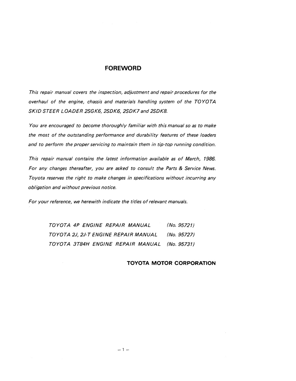
FOREWORD This repair manual covers the inspection, adjustment and repair procedures for the overhaul of the engine, chassis and materials handling system of the TOYOTA SKID STEER LOADER 2SGK6,2SDK6,2SDK7and 2SDK8. You are encouraged to become thoroughly familiar with this manual so as to make the most of the outstanding performance and durability features of these loaders and to perform the proper servicing to maintain them in tip-top running condition. This repair manual contains the latest information available as of March, 1986. For any changes thereafter, you are asked to consult the Parts & Service News. Toyota reserves the right to make changes in specifications without incurring any obligation and without previous notice. For your reference, we herewith indicate the titles of relevant manuals. TOYOTA 4P ENGINE REPAIR MANUAL (No. 95721) TOYOTA2J,2J-TENGINEREPAIRMANUAL (N0.95727) TOYOTA 3T84H ENGINE REPAIR MANUAL (No. 95731) TOYOTA MOTOR CORPORATION
SECTION INDEX I 1 1 AXLE I BRAKES L - - I BODY FRAME 1 1 - GENERAL ENGINE ' HYDROSTATIC TRANSMISSION FINAL REDUCTION GEAR A 1 LIFT ARMS & BUCKET BRACKET m CYLINDERS 0 0 I OIL PUMP I OIL CONTROL VALVE
GENERAL Page 0-2 ..................... VEHICLE EXTERIOR VIEWS .............................. VEHICLE MODELS 0-3 ................................. ABBREVIATION 0-3 TIPS ON OPERATION ........................... 0 4 RIGHT ORDER OF OPERATION .................. 0 4 STANDARD BOLT & NUT TIGHTENING TORQUE . . 0-5 STANDARD HIGH-PRESSURE HOSE FITTING TIGHTENING TORQUE ........................ 0-7 ........................ FRAME SERIAL NUMBER 0-7 VEHICLE DIMENSIONS .......................... 0-8 ...................... GENERAL SPEC1 FlCATlONS 0-12 RECOMMENDED LUBRICANTS & CAPACITIES ...... 0-14 ....................... .................................. PERIODIC MAINTENANCE 0-15 LUBRICATION 0-20
https://www.ebooklibonline.com Hello dear friend! Thank you very much for reading. Enter the link into your browser. The full manual is available for immediate download. https://www.ebooklibonline.com
VEHICLE MODELS I I 2SGK6 I 2SDK6 I I / 1 / 1 1 460 kg (1000 bs) 1 460 kg (1000 bs) 1 1 520 kg (1 150 bs) 1 031 m3 ( 1 1.0 ft3) / 2200 kg (4850 lbs) I 1 I Model Engine Operating Load Bucket Capacity 0.28 m3 (10.0 it3) 1 2100 kg (4630 bs) I 2100 kg (4630 lbs) I Machine Weight TOYOTA 4P YANMAR 3T84H / 0.28 m3 (10.0 it3) 2SDK7 TOYOTA 2J 2SDK8 TOYOTA 2J 600 kg (1 320 lbs) 0.34 m3 (1 2.0 ft3) 2490 kg (5490 Ibs)
TIPS ON OPERATION Safe operations (1) Carry out inspections and servicing with the lift arm lowered and the bucket on the ground. If such work must be performed with the lift arm in the air, support it with the lift arm lock pin, or use the safety block or safety pillar to prevent the arm from lowering. (2) Always use rigid racks or stands when jecking up the vehicle. (3) When lifting with a wire rope, make sure the rope is suffic~ently strong. SST & measuring tools Have the mechanic tools, SST and measuring tools on hand Order & arrangement (1 ) Always arrange things in an orderly manner for easy operations. (2) Disassembly of the hydraulics should be done with clean tools in a clean area Troubleshooting Do not immediately disassemble when trouble occurs; first determine whether or not dlsassembly is necessary. For example, wlth the HST, the pump should not be immediately turn down srmply because there is trouble with the travel system. Troubleshoot the cause in the steerlng levers, the final reduction gear, the change oil pressure, the hydraulic oil and so on. RIGHT ORDER OF OPERATION Disassembly Mark or punch matlng marks in a feasible location so as to facilitate dlsassembly of a complex unit. Also, if you are reparing electricals, be sure to disconnect the cables from the battery terminals. Always start with (-) terminal without fail when disconnecting cables from the battery term~nals. Inspections during disassembly In removing each and eavry part, check for the installed condition, deformation, breakage, roughness or damage. Assembly and installation (1) Always adhere to the tightening torques listed. If none are given, follow the "Standard Tighten- ing Torques." (2) When reassembling after disassembly, use Toyota Genuine Parts to replace packlngs, gaskets and O-rings. (3) Apply a seal pack~ng in terms of the gasket position, and coat the sliding surfaces at the specified locations with the recommended oil; apply the recommended grease and also coat oil seal lips with MP grease, when assembling.
STANDARD BOLT & NUT TIGHTENING TORQUE Standard bolt and nut tightening torques are not indicated; therefore tightening torque must be judged as below. Find out the type of the bolt from the list below. Then, find the bolt tightening torque frorn the table 1. The nut tightening torque can be judged from the bolt type. (See the table.) 2. List of Bolt Types and Strength 2. k - Judg~ng by part No. lexagon bolt 1 @ , ; re: 1. Judging by part I Shape and description Sample number ber in relief or hallmark on the 91 111-40610 Hexagon bolt I Length (mm): A Standard bottom surface No mark Hexagon bolt (Collared bottom) No mark I I Two re1 ief lines on I the head Hexagon bolt (Standard bottom surface) - , - I Stud bolt Hexagon bolt (Collared bottom) 0 I Sample number 921 32-,4O614 ; ; ; ; l i e f 1 ines on Hexagon bolt Length (mm): A Diameter (mm): B Type Welded bolt I No mark I Welding bolt Approximately 2 mm ' (0.08") hollow on I either or both ends Stud bolt BAHS2
Standard Bolt Tightening Torque Standard t~ghtening torque kg-cm (it-lb) Pitch mm Diameter r n m Seat with flange
STANDARD HIGH-PRESSURE HOSE FllTlNG TIGHTENING TORQUE 1. When connecting a high-pressure hose, always clean the hose f ~ t i ~ n g clean cloth. Check that there are no dents in the contacting surfaces. and The opposlng nipple with a 2. When connecting a high-pressure hose, always tighten so that the hose fitting and nipple he in a straight line and not off-center Standard tightening torque kg-m (ft-lb) Hose inside diameter Nominal Screw diameter Torque range Standard torque 7/16 - 20 UNF 9/16 - 18 UNF 314 - 16 UNF 718 - 14UNF 1-1/16 - 12 UNF 1-5/16 - 12 UNF FRAME SERIAL NUMBER 2. 1 . Frame Serial Number Location Frame Numbering System Vehicle model Serial number 2SG K6 2SGK6-10011 - - Frame Serial Number Location SAE45-13
VEHICLE DIMENSIONS MODEL: 2SGK6 J SAEMl Vehicle Dimensions (2SGK6) - 12 -
MODEL: 2SDK6 Vehicle Dimensions (2SDK6) - 13 -
MODEL: 2SDK7 Vehicle Dimensions (2SDK7) - 14 -
MODEL: 2SDK8 Vehicle Dimensions (2SDK8) - 15 -
GENERAL SPECIFICATIONS 2SG K6 2SD K6 2SDK7 2SDK8 l tem ( Performance ( T~pping load (SAE) 1 1 1040 (2290) 1200 (2640) 600 (1320) 46011000) 520 (1 150) Operating load (SAE) kg(Ibs) c 0.28 (10.0) 0.31 11 1 .O) 0.34 (12.0) c Bucket capacity m3 (cu-ft) 2210 (87.0) 2190 (86.2) 2160 (85.0) c Dump height (at 45') mm (in) Reach-fully ra~sed (at 45" I Dump angle lmax) I Ra~slng time (Full load) ( Lower~ng time (No load) I Dump time (Full load) deu 1 sec 1 1 I 1 I I 4.0 c t t / sec sec 1 2.5 c 4- c 1 I 2.5 t t c c 10 (6.2) c c Forward Travel speed kmlh (mph) Reverse 10 (6.2) c t t Clearance c~rcle (Bucket) mm (in) 1700 (67.0) 1730 (68.0) 1750 (69.0) c 1 1 ( Traction (Full load) 2100 (4650) 2400 (5300) c c c 30 t Gradeability % c c Reverse 58 t Engine c TOYOTA 4P TOYOTA 2J YANMAR 3T84H Model t 88 (3.46) Bore mm (in) 76.6 (3.02) 84 (3.31) Cylinder 102 (4.02) 81.0 (3.19) 85 (3.35) t Stroke mm (in) c 2481 (151) 1493 (91 ) 141 3 (86) Piston desplacement cc (cu-m) 5012500 4012500 2812500 3012400 PSIrpm Rated hosepower 4712500 Net 3812500 Net 2712500 Net H Plrpm 3812600 Gross 14.512200 12.012200 10,511 800 8.512000 kg-mlrpm Rated torque 8312200 Net 10012200 Net 5912000 Net 77/2600 Gross ft-lbslrpm *-3 *-2 1-1 *-a Overall length (with bucket) 2880 (1 13.5) 2845 (1 12.0) mm (in) 2810 (110.5) 4- Overall width (without bucket) + c c mm (in) 1520 (59.5)
Vehicle 2SDK6 2SDK7 2SDK8 2SG K6 I rnm (in) 1 1 1 Bucket width 1530 (60.0) c c t Overall height (operator guard) mm (in) 1925 (75.5) t t t I I I I rnm (ln) / t t Wheel base 915 (36.0) t c c Front 1250 (49.2) t Tread mm (in) t t C Rear 1250 (49.2) C C t 190 (7.5) Ground clearance rnm (in) c C t Center 300 (1 1.8) Machine weight (include a full fuel tank and bucket) kg (Ibs) X-5 2100 (4630) Controls - Hydrostatic Forward, Reverse, Variable Travel Speed and Steering Controlled by Two Hand Lever Steering - l ~ w o Hydrostatic Transm~ss~on wlth lnfin~ty Vanable Speed Drwe Fuel System 1 - - Fueltankcapacity P(US/UKgal)1 52114111) + Brake c c Foot brake (OPT) *-' Mechanical t I 1 / Hand brake Mechanical + + + Battery c 12/35 12/80 VIAH t c 332 622 CCA t Tires 10.00-1 6.5-4PR (OR) 10.00-1 6.5-4PR (OR) C Front t C Tire size c t t Rear " Specifications and design are subject to change without notice
RECOMMENDED LUBRICANTS & CAPACITIES Location Diesel engine oil API classif~cation over CC SAE 1 OW-30 Motor oil API classification over SD SAE20.30 Engine Motor oil API classification over SD SAE1 OW-30, SAE7.5W-30 Diesel engine 011 API classification over CC SAE5W-30 4 Q (1.06 US gal) 7Q (1.85 US gal) C Capacity I (*cold area) STD, Auto fluid OPT Type [ATF TYPE F1 Oil tank 2511 (6.6 US gal) ** Capacity I oil API classification over CC SAE 1 OW-30 Diesel engine STD, Reduction gear unit Type OPT ("Cold area) 16Q (4.22 US gal) Capacity 1611 (4.22 US gal) C Diaphragm oil Type Pneumatic governor 2 to 3 drops Capacity Mult~purpos grease C TY pe Lubrication ooints Proper amount Capacity Diesel fuel Gasoline Fuel tank 52Q (14 US gal) 1 Type pT ("Cold area) Long life coolant 30% STD Engine cooling system Long life coolant 50% 1.9Q 12.61 US gal 3.6P (2.53 US gal) 5.5Q 11.45 US gal) 6.2Q (1.64 US gal) Capacity : For use at a minimum temperature of -15OC to -25'C **: Precisely, capacity 25Q (6.6 US gal) must contain 1.5Q (0.4 US gal) of specified HST additive & Part No. 38999- 42800-71. in a cold season
PERIODIC MAINTENANCE INSPECTION METHOD I : Inspect and correct and replace as required. L : Lubricate M , Measure and correct and adjust as required. T . Tighten C : Clean INSPECTION PERIOD Carry out according to operating hours or months, whichever is soonest 3 1 6 12 Every 170 1000 500 Item Every 2000 Hours ENGINE Starting condition and unusual noise Rotating condition during idling Rotating condition during acceleration Basic com- oonents Exhaust condition Air cleaner element Valve clearance Compression Blow by gas Reduction Device Clogging and damage of PCV valve and piping I Maximum no-load speed I Governor Oil leakage Lubrication system Oil level Clogging and fouling of oil filter Fuel leakage Carburetor link mechanism operation Fouling and damage of fuel filter element I Fuel system Clogging of feed pump stainer Injection timing Injection nozzle injection pressure and condition I Radiator cooling water level and leakage Rubber hose deterioration I Cooling system Radiator cap condition Fan belt tension and damage For new vehicle ":
3 6 Every 1 12 500 1000 Every 2000 Hours 170 Item POWER TRANSMISSION SYSTEM Oil leak HST pump and motor operation, abnormal sound HST pump and motor HST charge pressure measurement HST working pressure measurement Oil leak Oil level Reduction gear unit Reduction gear operation, abnormal sound Chain bush engaged portion deformation Sprocket deformation, damage RUNNING EQUIPMENT Tire air pressure Tire cuts, damage and uneven treads Loose hub bolts and hub nuts Tread depth Wheels Metal fragments, stones or other forelgn objects in tires Rim, side ring and disc wheel damage Wheel bearing unusual noise and looseness Deformation, crack and damage Axle - STEERING SYSTEM I Looseness t C C Steering control lever I c Operation condition t t I Bending and damage + +- t Link rod c I + Installed portion looseness t BRAKE SYSTEM Play and reserve Brake pedal I c +- Braking effect +- I c +- Pull margin +- c c I Braking effect + - Parking brake Rod and cable looseness and damage Ratchet wear and damage - Brake disk and pad wear and damage - - M Disk brake
Suggest: For more complete manuals. Please go to the home page. https://www.ebooklibonline.com If the above button click is invalid. Please download this document first, and then click the above link to download the complete manual. Thank you so much for reading
I - - - - - - 1 Every 12 3 6 1 7 0 Item Every 500 1000 2 0 0 C Hours MATERIALS HANDLING EQUIPMENT - Bucket edge damage, wear Bucket Bucket deformation, damage and crack Bucket welded portion crack Lift arm and link deformation, damage and crack I I Lift arm and link Lift arm welded portion crack Stop lever, link and pin damage Bucket bracket deformation, damage and crack Bucket bracket Bucket bracket welded portion crack Any abnormality and installed state of each part attachments HYDRAULIC EQUIPMENT Cylinder installed portion looseness Cylinder and piston rod damage Rising speed, dumping speed Cylinder Oil pump + tank Cylinder operating condition, natural drop, natural forward tilt Cylinder oil leak Pin and cylinder bearing weark damage Oil leak, abnormal sound Oil amount and dirt Hydraulic oil Oil leak Tank and strainer I Each connecting portion looseness Operating pedal Pedal function Pedal lock funct~on Oil leak Oil control valve Safety valve function Rel~ef pressure measurement Oil leak, looseness measurement ELECTRIC EQUIPMENT Ignition system Distributor cap cracking I + + t Damage of contact breaker arm and point I c +- t
Every Every Hours Contact breaker point gap Spark plug burning and gap Ignition timing Ignition system Distributor side terminal burning Wear and damage of distributor cap center terminal Plug cord internal disconnection Pin~on qear meshinq Starter Charging function Wire harness damage and connector looseness Fuses Charger Electric wiring Glow plug heat coil breakage Pre-heater Thermo-start plug function Specific gravity SAFETY DEVICE AND OTHERS Installed portion looseness 3perator guard 2nd side guard Deformation, crank, damage Iirection ndicator Operation and installed state Warm unit Operation and installed state I Operation and installed state Operation and mstalled state I I b - b b J c +- c c +- I -amp unit 3everse alarm + I Dirt and damage c c +-- 3ack mirror I Back reflection state +- + - + I nstruments Each instrument operation c c t I Seat Looseness, damage c c c I Seat Belt Slackness, damage c c c I Frame, cross member, etc. damage, crack 3ady T Bolt looseness L 3thers Each part grease up + c t
https://www.ebooklibonline.com Hello dear friend! Thank you very much for reading. Enter the link into your browser. The full manual is available for immediate download. https://www.ebooklibonline.com

