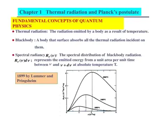
Thermal Radiation and Stefan-Boltzmann Law


RADIATION
HEAT TRANSFER
 
1
 
 
Thermal radiation is that electromagnetic radiation
emitted by a body as a result of its temperature.
Unlike conduction and convection, it requires no
matter for the transfer.  All electromagnetic
radiations are propagated at the speed of light, given
as the product of wavelength and frequency.


c = 
λν
1Å (angstrom) = 10
-8
 cm.
A portion of the electromagnetic spectrum is shown in
figchp11\fig11.1.pptx
Thermal radiation lies in the range about 0.1 to
100
μ
m.  The visible light is between 0.35 to 0.75
μ
m.


2
 
 
The modern theory views thermal radiation as the
propagation of a collection of particles called
photons or quanta with quantum of energy given by
  
E = h
ν
       h=6.625x10
-34
 J.s  (Planck’s constant)
Using  E = mc
2
 = h
ν
  one can find the momentum of a
photon as
Momentum  = mc = h
ν
/c
Quantum – statistical thermodynamics gives the
energy density of radiation per unit volume and per
unit wave length as


3
 
 
When the above is integrated over all wavelengths it
gives
 
 
The above is called the Stefan-Boltzmann law, E
b
 is
the energy(W) radiated per unit time and per unit
area by the ideal radiator, and 
σ
 is the Stefan-
Boltzmann constant given by
 
σ
 = 5.669x10
-8
 W/m
2
.K
4
 
 
4
 
 
Radiation Properties
When radiant energy is incident on a surface (called
irradiation), part of the radiation is reflected, part is
absorbed, and part is transmitted as shown in
figchp11\fig11.2.pptx
 .
For irradiation given by G
G = 
α
G +
ρ
G + 
τ
G   or 
α 
+
ρ
+
τ
 =1
α
 = Absorptivity  
ρ
 = Reflectivity 
τ
 = Transmissivity
For solid bodies that do not transmit
 
 α 
+
ρ
 =1
Two types of reflections:
Specular- incidence and reflection angles are
 
5
 
 
equal.
Diffuse – incident beam is distributed uniformly in all
directions after reflection 
figchp11\fig11.3.pptx
The emissive power of a body E is defined as the
energy emitted by the body per unit area per unit
time. Shown in 
figchp11\fig11.4.pptx
 
 the black
enclosure will absorb all the incident radiation
falling upon it.  It will also emit radiation according
to the T
4
 law.  Let the radiant flux arriving at some
area in the enclosure be q
i
 W/m
2
.  If a body is placed
inside the enclosure and allowed to come to
equilibrium, the energy absorbed and emitted by the
body are equal.


6
 
 
At equilibrium
  
EA = q
i
A
α
If the body had been a black body, then
  
 E
b
A = q
i
A(1)
The above will give the ratio of the emissive power of
a body to the emissive power of a blackbody at the
same temperature as the absorptivity.  This  ratio is
also defined as the emissivity 
ε
 of the body, given as


7
 
 
The equality of 
α
 and 
ε
 is called Kirchoff’s identity.
The Gray Body
A gray body has its monochromatic emissivity 
ε
λ
independent of the wavelength.  Monochromatic
emissivity is defined as the ratio of the
monochromatic emissive power of the body to the
monochromatic emissive power of a black body at
the same wavelength and temperature.


8
 
 
The total emissivity of the body and that of a
blackbody can be determined as
 
 
From the above


If the gray body condition is imposed, 
ε
λ
 = constant,
the above equation reduces to
  
 ε
 = 
ε
λ


9
 
 
It has to be noted that the emissivities of various
substances vary widely with wavelength,
temperature, and surface condition.
For a blackbody, according to Planck, E
b
λ
 (spectral
emissive power) is given by


λ=wavelength, 
μ
m
 
T=temperature, K
 
C
1
 = 3.743 x 10
8
 W.
μ
m
4
/m
2
 
C
2
 = 1.4387 x 10
4
 
μ
m . K


10
 
 
This emissive power is plotted in
figchp11\fig11.5.pptx
 . Close observation of the
curves shows a shift of the peak points to the shorter
wavelengths for higher temperatures.  This shift is
defined by Wien’s displacement law given by
  
λ
max
 T = 2897.6 
μ
m.K
The sun at 5800 K is considered as a black body. The
maximum emission is in the visible range and this
appears as white.  For a black body at 1000K, peak
emission occurs at 2.90 
μ
m (not visible),  with some
of the emitted radiation appearing visible as red
light.


11


figchp11\fig11.6.pptx
   shows the spectral energy
density of a black body at 1922 K, a corresponding
gray body with 
ε
 = 0.6 and approximate behavior of
a real surface.
Band Emissions
Frequently it will be of interest to get the amount of
energy radiated from a black body in a certain
specified wavelength range, 
figchp11\fig11.7.pptx
.
This is expressed as a fraction given by


12
 
 
Rearranging the spectral emission equation as
 
 
The results of the above have been tabulated (Table 1)
and graphically in 
figchp11\fig11.8.pptx
 .
For radiant energy emitted between wavelengths 
λ
1
and 
λ
2
 
 
From practical observations, ordinary glass  is
transparent to solar radiation while not transmitting


13
 
 
earthly radiations.  This is what is called the
greenhouse effect.
Solar radiation approximates that of a black body at
5800K.  Ordinary window glass transmits radiation
up to about 2.5 
μ
m.  This gives 
λ
T= 2.5 x 5800 =
14500 
μ
m.K.  Referring to the table, about 97 % of
the radiation emitted is transmitted through the
glass. Glass is transparent for solar radiation.
Whereas earthly radiations at about 300 K 
λ
T=2.5 x
300 = 750 
μ
m.K.  The table shows only a minute
fraction (less than 0.001 percent) of this radiation is
transmitted. Glass is opaque for earthly radiations.
There comes the greenhouse effect!


14
 
 
Example 11.1
A glass plate 30 cm square is used to view radiation
from a furnace.  The transmissivity of the glass is
0.5 from 0.2 to 3.5 
μ
m.  The emissivity may be
assumed to be 0.3 up to 3.5 
μ
m and 0.9 above that.
The transmissivity of the glass is zero, except in the
range from 0.2 to 3.5 
μ
m.  Assuming that the
furnace is a blackbody at 2000
o
C, calculate the
energy absorbed in the glass and the energy
transmitted.
Solution
  
T = 2000
o
C = 2273 K


15


λ
1
T = (0.2)(2273) = 454.6 
μ
m.K
  
λ
2
T = (3.5)(2273) = 7955.5 
μ
m.K
  
A = (0.3)
2
 = 0.09 m
2
From table


σT
4
 = (5.669 x 10
-8
)(2273)
4
 = 1.5133 x10
6
 W/m
2
Total incident radiation is
 
0.2 
μ
m < 
 λ
 <3.5 
μ
m
  
= (1513.3)(0.85443 - 0)0.09= 116.4 kW
Total radiation transmitted = (0.5) (116.4) = 58.2 kW


16


Total radiation absorbed = 34.92 +17.84 = 52.76 kW


17
 
 
Radiation Shape Factor
Given two black surfaces which see each other, as
shown in 
figchp11\fig11.9.pptx
 , a general
expression for energy exchange between such
surfaces at different temperatures will be required.
This will require the concept of radiation shape
factors or view factors.  These are defined as
follows.
 
F
1-2
 = fraction of energy leaving surface 1 which
 
      reaches surface 2
 
 F
2-1
 = fraction of energy leaving surface 2 which
 
      reaches surface 1
 
 F
m-n
 = fraction of energy leaving surface m which
 
      reaches surface n


18
 
 
The energy leaving surface 1 and arriving at surface 2
is       E
b1
A
1
F
12
and the energy leaving surface 2 and arriving at
surface 1 is       E
b2
A
2
F
21
All radiations falling on black surfaces will be
completely absorbed.
The net energy exchange is given by
Q
1-2
 = E
b1
A
1
F
12 
- E
b2
A
2
F
21
For T
1
 = T
2
,       Q
1-2
 =0
This will give A
1
F
12
  =  A
2
F
21
This reciprocity relation will hold true for all
situations.
 
 
19
 
 
The net heat exchange will therefore be
 
Q
1-2
 = A
1
F
12
(E
b1
 – E
b2
) = A
2
F
21
(E
b1
 – E
b2
)
The general reciprocity relation for any two surfaces i
and j will be
 
A
i
F
ij
 = A
j
F
ji
The direction of emission from dA
1
 is given with
reference to the zenith and azimuthal angles as
shown in 
figchp11\fig11.10.pptx
  .  This radiation
passes through a differential area dA
n
 which is
normal to the path of the radiation.  This area
subtends a solid angle d
ω
 when viewed from a point
on dA
1
. The similarity of the angle subtended by an
arc and
 
 
20
 
 
the solid angle subtended by an area is shown in
figchp11\fig11.11.pptx
 .  The plane angle d
α
 has a
unit of radians while that  of d
ω
  is the steradian (sr).
To determine a general relation for shape factors,
consider the angles 
θ
1
 and 
θ
2
, the angles with
reference to the normals of the surfaces.  The
projection of dA
1
 on the line between centers is
  
dA
1
 cos 
θ
1
The radiation intensity is that emitted per unit area and
per unit of solid angle in a certain specified
direction.  This is given by I
b
 considering a black
surface.


21
 
 
The differential solid angle can easily be determined as
shown in 
figchp11\fig11.12.pptx
 
. This is given by
 
 
Thus the energy leaving dA
1
 in the direction of 
θ
1
 is
 
I
b
 dA
1
 cos 
θ
1
The radiation arriving at some areal element dA
n
 at a
distance r from A
1 
would be
 
 
I
b
 dA
1
 cos 
θ
1
 
(d
ω
)
The intensity from the differential area can be determined
in terms of the emissive power by


22
 
 
integrating over a hemisphere enclosing the elemental
area dA
1 
as shown in 
figchp11\fig11.13.pptx
 
.


 With respect to the line, r,  connecting the two
differential areas dA
1
 and dA
2
, the area dA
n
 is given
by
 
dA
n
 = cos 
θ
2
 dA
2
This will give the energy leaving dA
1
 and arriving


23
 
 
at dA
2
 as


And the energy leaving dA
2
 and arriving at dA
1
 will be


As the integrals are exactly the same, the above
equations give the reciprocity relation
  
A
i
F
ij
 = A
j
F
ji


24
 
 
The view factor for an enclosure with N surfaces with
temperatures T
1
, T
2
, …., T
N
 is given by
 
 
The term F
ii
 is non zero if it sees itself.
For radiation exchange in an enclosure of N surfaces,
a total of N
2 
view factors is needed as arranged  in
the matrix form


25
 
 
Out of this N
2
 view factors, which require N
2
equations, there are N equations formed by the
summation rule and N(N-1)/2 equations formed by
the reciprocity relations. This will then require only
(N
2
-N(N-1)/2)=N(N-1)/2 view factors to be
determined.  For a three surface enclosure we need
to determine three view factors only to completely
determine the view factors.
As an example consider a two surface enclosure
involving two spheres as shown in
figchp11\fig11.15.pptx
 .  For this we will need to
determine four view factors (F
11
, F
12
, F
21
, F
22
).


26
 
 
Only N(N-1)/2 view factors need to be determined to
completely get the values of the view factors. One
view factor is to be determined directly.  By
inspection F
11
 = 0 .  For the rest use the equations
formed by summation given by
  
F
11
 + F
12
 =1
  
 F
12 
=1
  
F
21
 + F
22
 =1
And the reciprocity relation
  
A
1
F
12
 = A
2
F
21
(three equations and three unknowns)
     F
21
= A
2
 /A
1
      F
22
  = 1 - F
21
  = 1 - A
2
 /A
1


27
 
 
For other complicated geometries, the double integral
equations have been solved and the results given in
tables and graphs.(tables 2&3, and graphs 1, 2, and
3)
For view factors to a subdivided surface shown in
figchp11\fig11.14.pptx
, consider the radiation from
surface i to surface j, which is divided into n
components, the view factor is given as a summation


28
 
 
The view factor when radiation originates from a
subdivided surface can be determined as follows:
Multiplying the above equation by A
i
 and applying the
reciprocity relation gives


29
 
 
Example 11.2
Consider a diffuse circular disk of diameter D and area
A
j
 and a plane diffuse surface of area A
i
 <<A
j
.  The
surfaces are parallel, and A
i
 is located at a distance L
from the centre of A
j
.  Obtain an expression for the
view factor F
ij
.
 
30
 
 
Solution
We will use
 
θ
i
, 
θ
j
, and R are approximately independent of position
on A
i
, the above reduces to
 
 
Using R
2
 =r
2
 +L
2
, cos 
θ
 = (L/R) and dA
j
 = 2
π
rdr , the
integration will give


31
 
 
Example 11.3
Determine all the view factors for the following
geometries.
1.
Sphere of diameter D inside a cubical box of length
L=D.
2.
Diagonal partition within a long square duct.
3.
End and side of a circular tube of equal length and
diameter.


32
 
 
Solution


1.  Sphere within a cube:
 
F
12
 =1        F
21
 = (A
1
/A
2
)F
12
 = (
π
D
2
/(6L
2
)x1 = 
π
/6
From summation relation
 
F
11
 + F
12
 = 1      →  F
11
 = 0
 
F
21
 + F
22
 = 1      →  F
22
 = (1-
 π
/6)
 
 
33
 
 
2.
Partition within a square duct
By inspection 
F
11
 = 
F
22
 = 
F
33
 = 0
Summation equations
 
F
12
 + F
13
 = 1  (symmetry 
F
12
 
= 
F
13
 =0.5)
 
F
21
 + F
23
 = 1
 
F
31
 + F
32
 = 1
A
2
 = A
3
 = L       A
1
 = (√2)L
Reciprocity
 
A
1
F
13
 = A
3
F
31
    
F
31
 = (A
1
/A
3
)F
13
= (√2)F
13
=0.71
 
A
1
F
12
 = A
2
F
21
    
F
21
 = (A
1
/A
2
)F
12
=(√2)F
12 
=0.71
 
A
2
F
23
 = A
3
F
32
    F
32
 = (A
2
/A
3
)F
23
= F
23
 
F
23
 = 1-F
21
=1-0.71=0.29
 
F
32
 = F
23
 = 0.29


34
 
 
3. Circular tube:
 
Using Graph 2  with r
3
/L = 0.5 and L/r
1
 = 2  will give 
F
31
≈0.17
 
F
11
 = 0  
F
33
 = 0
A
1
 = A
3
 = (
π
D
2
/4)       A
2
 = 
π
D
2
Summation equations
 
F
12
 + F
13
 = 1
 
F
21
 + F
22
 + F
23
 = 1  (symmetry    F
21
 = F
23
)
 
F
31
 + F
32
 = 1            (
F
32
 = 1-F
31
 = 0.83)
Reciprocity
A
2
F
23
 = A
3
F
32
    
F
23
 = (A
3
/A
2
)F
32
= (1/4)F
32
=0.208        
F
21
=0.208
 
A
1
F
13
 = A
3
F
31
    
F
13
 = (A
3
/A
1
)F
31
= F
31
=0.17
 
F
22
 = 1 – (F
21
 + F
23
) = 0.58
 
A
1
F
12
 = A
2
F
21
    
F
12
 = (A
2
/A
1
)F
21
=(4)F
21
=0.83


35
 
 
Radiation Exchange Between Surfaces
When radiation falls on an opaque surface there will
be a possibility of absorption and reflection.  In an
enclosure there will be multiple reflections with
partial absorptions.
Blackbody Radiation Exchange
The simplest radiation exchange will be between black
surfaces where there will be no possibility of
reflection.
The following terms will need to be defined.
G = irradiation
 
= total radiation incident upon a surface per unit
time per unit area


36
 
 
J = radiosity
 
= total radiation which leaves a surface per unit time
per unit area
For a black surface radiosity is the same as the
emission.
For the analysis of radiative heat transfer between
black surfaces, we will use 
figchp11\fig11.16.pptx
.
Define q
i→j
 as the rate at which radiation leaves
surface i and is intercepted by surface j.  This can be
expressed as


37


This will allow the construction of a thermal network
that satisfies


38
 
 
For surface i being in an enclosure and interacting
with N surfaces at different temperatures, the above
equation can extended to


Example 11.4
A furnace cavity, which is in the form of a cylinder of
75 mm diameter and 150 mm length, is open at one
end to large surroundings that are at 27
o
C.  The sides
and bottom, which may be approximated as black
bodies, are heated electrically, well insulated,


39
 
 
and maintained at temperatures of 1350 and 1650
o
C,
respectively.  How much power is required to
maintain the furnace conditions.


40
 
 
Solution


Since the surrounding is large it may be treated as a
black body. Here the heat transfer by convection will
be assumed to be negligible compared to the
radiative heat transfer.


41
 
 
With T
3
 = T
sur
, the heat loss can be expressed as
 
q = q
13 
+ q 
23
Using appropriate equations for radiation between
black surfaces
 
For the two opposing surfaces (top and bottom), using
(r
j
/L) = (0.0375/0.15) = 0.25 and
   (L/r
i
) = (0.15/0.375) = =4
 
F
23
 = 0.06   (From view factor graphs)
Use summation rule
   F
21
 + F
23
 =1        F
21
 = 1-0.006 = 0.94


42
 
 
Use reciprocity relation
 
A
1
F
12
 = A
2
F
21
        to get
 
 
From symmetry F
13
 = F
12
Substitution in q gives


43


q = 1639 +205 = 1844 W
 
Radiative exchange between nonblackbodies
Here for an opaque body, the radiosity will also
involve the reflected part from the irradiation as
shown in 
figchp11\fig11.17.pptx
 .  More
complication is when the reflection is back and forth
between the heat transfer surfaces several times.
The radiosity is given by
 
J = 
ε
E
b
 +
ρ
G
Using  
ρ
 = 1 – 
α
 = 1- 
ε
 
44
 
 
the radiosity expression becomes
 
J = 
ε
E
b
 + (1 – 
ε
)G    G = (J - 
ε
E
b
 )/(1 – 
ε
)
The difference between the radiosity and the
irradiation gives net energy leaving the surface as
(q/A) = J – G =J - (J - 
ε
E
b
 )/(1 – 
ε
)
After substitution of G and simplification gives
 
 
The above allows the construction of a network with
the surface resistance as indicated.


45
 
 
If we consider the radiant energy exchange between
two surfaces, A
1
 and A
2
, the net heat transfer from
surface 1 to surface 2 can easily be determined as
 
 
q
1-2
 = J
1
A
1
F
12
 – J
2
A
2
F
21
Using the reciprocity relation    A
1
F
12
=A
2
F
21
 
 q
1-2
 = (J
1
– J
2
)A
1
F
12
 = (J
1
– J
2
) A
2
F
21
For network construction the above can be written as
 
 
where the resistance is indicated as space resistance.


46
 
 
The radiation exchange between two surfaces which
exchange heat with each other and nothing else can be
represented as a network given by
figchp11\fig11.18.pptx
 
.  From this network the net
heat transfer from surface 1 to surface 2 can easily be
determined as


 For other two surface enclosures, Table 4  gives the
necessary information.


47
 
 
For a three body problem, the network is given in
figchp11\fig11.19.pptx
 .
 
 
Kirchoff’s current law can be used to determine the
radiosities.  Sum of heat transfers to a node is zero.
This can be extended for a radiative interaction of a
surface with other surfaces that form an enclosure as
 
 
For any number N of surfaces forming the enclosure
there will be N equations with J
N
 unknowns.


48
 
 
Radiation Shields
Radiation shields use low emissivity materials (high
reflectivity) placed between radiating surfaces as
shown in 
figchp11\fig11.20.pptx
  (a).
If such a surface is placed additional surface and space
resistances will be created, thus reducing the heat
transfer.  The network is shown in (b).  The heat
transfer rate can easily be determined from the series
resistance network as


49
 
 
Insulated surfaces and Surfaces with large areas
.
For a perfectly insulated surface or that reradiates all
the energy incident upon it, the heat flow from such
a surface is zero.  This makes the potential
difference across the surface resistance to be zero,
resulting in J=E
b
.  The insulated surface does not
have zero resistance.


50
 
 
Large surface area (A→∞) has a surface resistance
approaching zero.  This behaves as a black body as
it tends to absorb all the radiant energy falling on it.
For this the surface resistance is zero (
ε
=1) and this
gives J = E
b
.  Thus the two cases – insulated surface
and surface with a large area – both have J = E
b
 .
If two flat or convex surfaces are connected by or
enclosed in a reradiating surface as shown in the
combustion furnace (
figchp11\fig11.21.pptx
 for the
schematic 
figchp11\fig11.22.pptx
 
), as no net heat is
exchanged with this body, J
R
 = E
bR
.
 
F
1R
 = 1 – F
12           
F
11
 = F
22
 = 0
 
F
2R
 = 1 – F
21
 
 
51
 
 
The network is a simple series parallel arrangement
which can be shown to give


After determining  J
1
 and J
2
, then J
R
 can be determined
from
 
 
Since              the temperature of the reradating surface
can be determined


52
 
 
Example 11.5
A paint baking oven consists of a long, triangular duct
in which a heated surface is maintained at 1200 K
and another surface is insulated.  Painted panels,
which are maintained at 500 K, occupy the third
surface.  The triangle is of width W = 1 m on a side,
and the heated insulated surfaces have an emissivity
of 0.8.  The emissivity of the panels  is 0.4.  During
the steady-state operation, at what rate must energy
be supplied to the heated side per unit length of the
duct to maintain its temperature at 1200 K?  What is
the temperature of the insulation surface?


53
 
 
Solution
The system will be modeled as a three surface
enclosure as shown in the figure below


54
 
 
1.  The heat transfer rate to be supplied is determined
from


Symmetry:  F
12
 = F
1R
 = F
2R
 
A
1
 = A
2
 = WL           L is length of duct


55
 
 
2.  For the temperature of the insulated surface use
will be made of the equality of J
R
 and E
bR
.  To get J
R
use


56
 
 
Substitution gives


57
 
 
M


58
Slide Note
Embed
Share

Thermal radiation is the electromagnetic radiation emitted by a body due to its temperature, propagating even in the absence of matter. The modern theory explains it as the propagation of photons with energy quantized by Planck's constant. Integrating over all wavelengths gives the Stefan-Boltzmann law, relating energy radiated by an ideal radiator to temperature. Properties of radiation include reflection, absorption, and transmission, with emissive power defined as energy emitted per unit area per unit time.

  • Thermal Radiation
  • Stefan-Boltzmann Law
  • Electromagnetic Radiation
  • Quantum Theory
  • Emissive Power

Uploaded on Jul 11, 2024 | 0 Views


Download Presentation

Please find below an Image/Link to download the presentation.

The content on the website is provided AS IS for your information and personal use only. It may not be sold, licensed, or shared on other websites without obtaining consent from the author. Download presentation by click this link. If you encounter any issues during the download, it is possible that the publisher has removed the file from their server.

E N D

Presentation Transcript


  1. RADIATION HEAT TRANSFER 1

  2. Thermal radiation is that electromagnetic radiation emitted by a body as a result of its temperature. Unlike conduction and convection, it requires no matter for the transfer. All electromagnetic radiations are propagated at the speed of light, given as the product of wavelength and frequency. c = 1 (angstrom) = 10-8 cm. A portion of the electromagnetic spectrum is shown in figchp11\fig11.1.pptx Thermal radiation lies in the range about 0.1 to 100 m. The visible light is between 0.35 to 0.75 m. 2

  3. The modern theory views thermal radiation as the propagation of a collection of particles called photons or quanta with quantum of energy given by E = h h=6.625x10⁻³⁴J.s (Planck s constant) Using E = mc2 = h one can find the momentum of a photon as Momentum = mc = h /c Quantum statistical thermodynamics gives the energy density of radiation per unit volume and per unit wave length as Boltzmann k e 38066 . 1 = 5 8 hc / = = tan u cons t hc kT 1 23 10 / K . x J molecule 3

  4. When the above is integrated over all wavelengths it gives 4 T Eb = The above is called the Stefan-Boltzmann law, Eb is the energy(W) radiated per unit time and per unit area by the ideal radiator, and is the Stefan- Boltzmann constant given by = 5.669x10⁻⁸ W/m2.K4 4

  5. Radiation Properties When radiant energy is incident on a surface (called irradiation), part of the radiation is reflected, part is absorbed, and part is transmitted as shown in figchp11\fig11.2.pptx . For irradiation given by G G = G + G + G or + + =1 = Absorptivity = Reflectivity = Transmissivity For solid bodies that do not transmit + =1 Two types of reflections: Specular- incidence and reflection angles are 5

  6. equal. Diffuse incident beam is distributed uniformly in all directions after reflection figchp11\fig11.3.pptx The emissive power of a body E is defined as the energy emitted by the body per unit area per unit time. Shown in figchp11\fig11.4.pptx the black enclosure will absorb all the incident radiation falling upon it. It will also emit radiation according to the T4 law. Let the radiant flux arriving at some area in the enclosure be qi W/m2. If a body is placed inside the enclosure and allowed to come to equilibrium, the energy absorbed and emitted by the body are equal. 6

  7. At equilibrium EA = qiA If the body had been a black body, then EbA = qiA(1) The above will give the ratio of the emissive power of a body to the emissive power of a blackbody at the same temperature as the absorptivity. This ratio is also defined as the emissivity of the body, given as E = = E b 7

  8. The equality of and is called Kirchoffs identity. The Gray Body A gray body has its monochromatic emissivity independent of the wavelength. Monochromatic emissivity is defined as the ratio of the monochromatic emissive power of the body to the monochromatic emissive power of a black body at the same wavelength and temperature. E = E b 8

  9. The total emissivity of the body and that of a blackbody can be determined as = = = 4 E E d and E E d T b b b 0 0 From the above E d E b = = 0 4 E T b If the gray body condition is imposed, = constant, the above equation reduces to = 9

  10. It has to be noted that the emissivities of various substances vary widely with wavelength, temperature, and surface condition. For a blackbody, according to Planck, Eb (spectral emissive power) is given by 5 u c C = = 1 E b / C T 4 1 e 2 =wavelength, m T=temperature, K C1 = 3.743 x 10⁸ W. m4/m2 C2 = 1.4387 x 10⁴ m . K 10

  11. This emissive power is plotted in figchp11\fig11.5.pptx . Close observation of the curves shows a shift of the peak points to the shorter wavelengths for higher temperatures. This shift is defined by Wien s displacement law given by max T = 2897.6 m.K The sun at 5800 K is considered as a black body. The maximum emission is in the visible range and this appears as white. For a black body at 1000K, peak emission occurs at 2.90 m (not visible), with some of the emitted radiation appearing visible as red light. 11

  12. figchp11\fig11.6.pptx shows the spectral energy density of a black body at 1922 K, a corresponding gray body with = 0.6 and approximate behavior of a real surface. Band Emissions Frequently it will be of interest to get the amount of energy radiated from a black body in a certain specified wavelength range, figchp11\fig11.7.pptx. This is expressed as a fraction given by = d E b d E E b b 0 0 E b 0 0 12

  13. Rearranging the spectral emission equation as C T E = = ( ) 1 b f T / C T 5 5 ( ) ( ) 1 T e 2 The results of the above have been tabulated (Table 1) and graphically in figchp11\fig11.8.pptx . For radiant energy emitted between wavelengths 1 and 2 E E b b E b b = = 4 E E E T 0 2 0 1 b b b E 1 2 0 0 0 0 From practical observations, ordinary glass is transparent to solar radiation while not transmitting 13

  14. earthly radiations. This is what is called the greenhouse effect. Solar radiation approximates that of a black body at 5800K. Ordinary window glass transmits radiation up to about 2.5 m. This gives T= 2.5 x 5800 = 14500 m.K. Referring to the table, about 97 % of the radiation emitted is transmitted through the glass. Glass is transparent for solar radiation. Whereas earthly radiations at about 300 K T=2.5 x 300 = 750 m.K. The table shows only a minute fraction (less than 0.001 percent) of this radiation is transmitted. Glass is opaque for earthly radiations. There comes the greenhouse effect! 14

  15. Example 11.1 A glass plate 30 cm square is used to view radiation from a furnace. The transmissivity of the glass is 0.5 from 0.2 to 3.5 m. The emissivity may be assumed to be 0.3 up to 3.5 m and 0.9 above that. The transmissivity of the glass is zero, except in the range from 0.2 to 3.5 m. Assuming that the furnace is a blackbody at 2000oC, calculate the energy absorbed in the glass and the energy transmitted. Solution T = 2000oC = 2273 K 15

  16. 1T = (0.2)(2273) = 454.6 m.K 2T = (3.5)(2273) = 7955.5 m.K A = (0.3)2 = 0.09 m2 From table E b E b = = 0 85443 . 0 0 1 0 2 4 4 T T T4 = (5.669 x 10⁻⁸)(2273)4 = 1.5133 x10⁶ W/m2 Total incident radiation is 0.2 m < <3.5 m = (1513.3)(0.85443 - 0)0.09= 116.4 kW Total radiation transmitted = (0.5) (116.4) = 58.2 kW 16

  17. Radiation = 1 ( 9 . 0 absorbed ) 4 . 116 )( 3 . 0 ( = 17 . 34 92 . 0 5 . 3 kW 3 . for . 0 )( m = = 85443 . 0 1513 )( 09 ) 84 kW 5 . 3 for m Total radiation absorbed = 34.92 +17.84 = 52.76 kW 17

  18. Radiation Shape Factor Given two black surfaces which see each other, as shown in figchp11\fig11.9.pptx , a general expression for energy exchange between such surfaces at different temperatures will be required. This will require the concept of radiation shape factors or view factors. These are defined as follows. F1-2 = fraction of energy leaving surface 1 which reaches surface 2 F2-1 = fraction of energy leaving surface 2 which reaches surface 1 Fm-n = fraction of energy leaving surface m which reaches surface n 18

  19. The energy leaving surface 1 and arriving at surface 2 is Eb1A1F12 and the energy leaving surface 2 and arriving at surface 1 is Eb2A2F21 All radiations falling on black surfaces will be completely absorbed. The net energy exchange is given by Q1-2 = Eb1A1F12 - Eb2A2F21 For T1 = T2, Q1-2 =0 This will give A1F12 = A2F21 This reciprocity relation will hold true for all situations. 19

  20. The net heat exchange will therefore be Q1-2 = A1F12(Eb1 Eb2) = A2F21(Eb1 Eb2) The general reciprocity relation for any two surfaces i and j will be AiFij = AjFji The direction of emission from dA1 is given with reference to the zenith and azimuthal angles as shown in figchp11\fig11.10.pptx . This radiation passes through a differential area dAn which is normal to the path of the radiation. This area subtends a solid angle d when viewed from a point on dA1. The similarity of the angle subtended by an arc and 20

  21. the solid angle subtended by an area is shown in figchp11\fig11.11.pptx . The plane angle d has a unit of radians while that of d is the steradian (sr). To determine a general relation for shape factors, consider the angles 1 and 2, the angles with reference to the normals of the surfaces. The projection of dA1 on the line between centers is dA1 cos 1 The radiation intensity is that emitted per unit area and per unit of solid angle in a certain specified direction. This is given by Ib considering a black surface. 21

  22. The differential solid angle can easily be determined as shown in figchp11\fig11.12.pptx . This is given by dAn = =sin 2 d d d r Thus the energy leaving dA1 in the direction of 1 is Ib dA1 cos 1 The radiation arriving at some areal element dAn at a distance r from A1 would be Ib dA1 cos 1(d ) The intensity from the differential area can be determined in terms of the emissive power by 22

  23. integrating over a hemisphere enclosing the elemental area dA1 as shown in figchp11\fig11.13.pptx . dA I dA E = 0 0 2 / 2 sin cos d d 1 1 b b = = I dA 1 b I E b b With respect to the line, r, connecting the two differential areas dA1 and dA2, the area dAn is given by dAn = cos 2 dA2 This will give the energy leaving dA1 and arriving 23

  24. at dA2 as dA dA = = cos cos cos 1 2 dq I dA d E 1 2 1 1 1 1 2 b b 2 r dA dA = = cos cos 1 2 q E E A F 1 2 1 1 2 1 1 12 b b 2 r A A 1 2 And the energy leaving dA2 and arriving at dA1 will be dA E dq b = dA cos cos 1 2 2 1 2 1 2 2 r dA dA = = cos cos 1 2 q E E A F 2 1 2 1 2 2 2 21 b b 2 r A A 1 2 As the integrals are exactly the same, the above equations give the reciprocity relation AiFij = AjFji 24

  25. The view factor for an enclosure with N surfaces with temperatures T1, T2, ., TN is given by = j 1 N = 1 ij F The term Fii is non zero if it sees itself. For radiation exchange in an enclosure of N surfaces, a total of N2 view factors is needed as arranged in the matrix form F 1 ...... F F F 11 12 1 N ...... F F F 21 22 2 N . . . . . . ...... F F 2 N N NN 25

  26. Out of this N2 view factors, which require N2 equations, there are N equations formed by the summation rule and N(N-1)/2 equations formed by the reciprocity relations. This will then require only (N2-N(N-1)/2)=N(N-1)/2 view factors to be determined. For a three surface enclosure we need to determine three view factors only to completely determine the view factors. As an example consider a two surface enclosure involving two spheres as shown in figchp11\fig11.15.pptx . For this we will need to determine four view factors (F11, F12, F21, F22). 26

  27. Only N(N-1)/2 view factors need to be determined to completely get the values of the view factors. One view factor is to be determined directly. By inspection F11 = 0 . For the rest use the equations formed by summation given by F11 + F12 =1 F21 + F22 =1 And the reciprocity relation A1F12 = A2F21 (three equations and three unknowns) F21= A2 /A1 F22 = 1 - F21 = 1 - A2 /A1 F12 =1 27

  28. For other complicated geometries, the double integral equations have been solved and the results given in tables and graphs.(tables 2&3, and graphs 1, 2, and 3) For view factors to a subdivided surface shown in figchp11\fig11.14.pptx, consider the radiation from surface i to surface j, which is divided into n components, the view factor is given as a summation = n = ( [ ) 2 , 1 ( to ,..., ,... )] F F j equivalent k n ( ) i j ik 1 k 28

  29. The view factor when radiation originates from a subdivided surface can be determined as follows: Multiplying the above equation by Ai and applying the reciprocity relation gives = k 1 n = = A F A F A F ( ) ( ) ( ) i i j j j i k ki n = k A F k ki = 1 F ( ) j i n = k A k 1 29

  30. Example 11.2 Consider a diffuse circular disk of diameter D and area Aj and a plane diffuse surface of area Ai <<Aj. The surfaces are parallel, and Ai is located at a distance L from the centre of Aj. Obtain an expression for the view factor Fij. 30

  31. Solution We will use dA dA 1 i A i R j = cos cos F ij i j 2 A A j i i, j, and R are approximately independent of position on Ai, the above reduces to cos cos j ij j R 2 cos i j = = = ( ) F dA dA j i j 2 2 R A A j Using R2 =r2 +L2, cos = (L/R) and dAj = 2 rdr , the integration will give rdr L F ij + 2 D + / 2 D = = 2 2 2 2 2 2 2 ( ) 4 r L D L 0 31

  32. Example 11.3 Determine all the view factors for the following geometries. 1. Sphere of diameter D inside a cubical box of length L=D. 2. Diagonal partition within a long square duct. 3. End and side of a circular tube of equal length and diameter. 32

  33. Solution 1. Sphere within a cube: F12 =1 F21 = (A1/A2)F12 = ( D2/(6L2)x1 = /6 From summation relation F11 + F12= 1 F11 = 0 F21 + F22= 1 F22 = (1- /6) 33

  34. 2. Partition within a square duct By inspection F11 = F22 = F33 = 0 Summation equations F12 + F13 = 1 (symmetry F12 = F13 =0.5) F21 + F23 = 1 F31 + F32 = 1 A2 = A3 = L A1= ( 2)L Reciprocity A1F13 = A3F31 F31 = (A1/A3)F13= ( 2)F13=0.71 A1F12 = A2F21 F21 = (A1/A2)F12=( 2)F12 =0.71 A2F23 = A3F32 F32 = (A2/A3)F23= F23 F23 = 1-F21=1-0.71=0.29 F32 = F23 = 0.29 34

  35. 3. Circular tube: Using Graph 2 with r3/L = 0.5 and L/r1 = 2 will give F31 0.17 F11 = 0 F33 = 0 A1 = A3 = ( D2/4) A2 = D2 Summation equations F12 + F13 = 1 F21 + F22 + F23 = 1 (symmetry F21 = F23) F31 + F32 = 1 (F32 = 1-F31 = 0.83) Reciprocity A2F23 = A3F32 F23 = (A3/A2)F32= (1/4)F32=0.208 F21=0.208 A1F13 = A3F31 F13 = (A3/A1)F31= F31=0.17 F22 = 1 (F21 + F23) = 0.58 A1F12 = A2F21 F12 = (A2/A1)F21=(4)F21=0.83 35

  36. Radiation Exchange Between Surfaces When radiation falls on an opaque surface there will be a possibility of absorption and reflection. In an enclosure there will be multiple reflections with partial absorptions. Blackbody Radiation Exchange The simplest radiation exchange will be between black surfaces where there will be no possibility of reflection. The following terms will need to be defined. G = irradiation = total radiation incident upon a surface per unit time per unit area 36

  37. J = radiosity = total radiation which leaves a surface per unit time per unit area For a black surface radiosity is the same as the emission. For the analysis of radiative heat transfer between black surfaces, we will use figchp11\fig11.16.pptx. Define qi j as the rate at which radiation leaves surface i and is intercepted by surface j. This can be expressed as 37

  38. = = ( ) q A J F A F E i j i i ij i ij bi Similarly = q A F E j i j ji bj Net radiative exchange will be = q q q ij i j j gives i Substituti = on = = 4 4 j ( ) ( ) q A F E A F E A F J J A F T T ij i ij bi j ji bj i ij i j i ij i This will allow the construction of a thermal network that satisfies ij ij i F A F A / 1 J J 1 i j = = q R 38 i ij

  39. For surface i being in an enclosure and interacting with N surfaces at different temperatures, the above equation can extended to N = 4 4 j ( ) q A F T T i i ij i = 1 j Example 11.4 A furnace cavity, which is in the form of a cylinder of 75 mm diameter and 150 mm length, is open at one end to large surroundings that are at 27oC. The sides and bottom, which may be approximated as black bodies, are heated electrically, well insulated, 39

  40. and maintained at temperatures of 1350 and 1650oC, respectively. How much power is required to maintain the furnace conditions. 40

  41. Solution Since the surrounding is large it may be treated as a black body. Here the heat transfer by convection will be assumed to be negligible compared to the radiative heat transfer. 41

  42. With T3 = Tsur, the heat loss can be expressed as q = q13 + q 23 Using appropriate equations for radiation between black surfaces ) ( 2 3 1 13 1 A T T F A q + = 4 4 4 4 ( ) F T T 23 2 3 For the two opposing surfaces (top and bottom), using (rj/L) = (0.0375/0.15) = 0.25 and (L/ri) = (0.15/0.375) = =4 F23 = 0.06 (From view factor graphs) Use summation rule F21 + F23 =1 F21 = 1-0.006 = 0.94 42

  43. Use reciprocity relation A1F12 = A2F21 to get A F . 0 ( 2 075 ) / 4 = = = . 0 x 94 . 0 118 2 F 12 21 . 0 ( 075 . 0 )( 15 ) A 1 From symmetry F13 = F12 Substitution in q gives . 0 ( = x q 8 75 . 0 x 15 . 0 )( 118 + . 5 67 10 x x 4 4 2 . 0 ( 1623 [( ) 300 ( ) ] 075 ) . 0 x 06 4 8 4 4 . 5 x 67 10 x 1923 [( ) 300 ( ) ] 43

  44. q = 1639 +205 = 1844 W Radiative exchange between nonblackbodies Here for an opaque body, the radiosity will also involve the reflected part from the irradiation as shown in figchp11\fig11.17.pptx . More complication is when the reflection is back and forth between the heat transfer surfaces several times. The radiosity is given by J = Eb + G Using = 1 = 1- 44

  45. the radiosity expression becomes J = Eb + (1 )G G = (J - Eb )/(1 ) The difference between the radiosity and the irradiation gives net energy leaving the surface as (q/A) = J G =J - (J - Eb )/(1 ) After substitution of G and simplification gives A q b 1 ( 1 E J = = ( ) b E J or q / ) A The above allows the construction of a network with the surface resistance as indicated. 45

  46. If we consider the radiant energy exchange between two surfaces, A1 and A2, the net heat transfer from surface 1 to surface 2 can easily be determined as q1-2 = J1A1F12 J2A2F21 Using the reciprocity relation A1F12=A2F21 q1-2 = (J1 J2)A1F12 = (J1 J2) A2F21 For network construction the above can be written as J J q = 1 2 1 2 / 1 A F 1 12 where the resistance is indicated as space resistance. 46

  47. The radiation exchange between two surfaces which exchange heat with each other and nothing else can be represented as a network given by figchp11\fig11.18.pptx . From this network the net heat transfer from surface 1 to surface 2 can easily be determined as 2 1 1 1 1 F A A E E = b b q net + + 1 2 A 1 1 1 T 12 2 ) 2 4 4 ( T = 1 2 1 1 F 1 + + 1 2 A A A 1 1 1 12 2 2 For other two surface enclosures, Table 4 gives the necessary information. 47

  48. For a three body problem, the network is given in figchp11\fig11.19.pptx . J J q = = J J 1 3 1 2 q 1 2 1 3 / 1 / 1 A F A F 1 12 1 13 Kirchoff s current law can be used to determine the radiosities. Sum of heat transfers to a node is zero. This can be extended for a radiative interaction of a surface with other surfaces that form an enclosure as = j ij i i i i F A A 1 ( / ) 1 ( J J ) N E J = i j = bi i q i 1 For any number N of surfaces forming the enclosure there will be N equations with JN unknowns. 48

  49. Radiation Shields Radiation shields use low emissivity materials (high reflectivity) placed between radiating surfaces as shown in figchp11\fig11.20.pptx (a). If such a surface is placed additional surface and space resistances will be created, thus reducing the heat transfer. The network is shown in (b). The heat transfer rate can easily be determined from the series resistance network as 2 1 1 12 1 1 1 1 4 4 ( ) A T T = q + + + 1 , 3 2 , 3 1 2 1 , 3 2 , 3 49

  50. Insulated surfaces and Surfaces with large areas. For a perfectly insulated surface or that reradiates all the energy incident upon it, the heat flow from such a surface is zero. This makes the potential difference across the surface resistance to be zero, resulting in J=Eb. The insulated surface does not have zero resistance. 50

More Related Content

giItT1WQy@!-/#giItT1WQy@!-/#giItT1WQy@!-/#