Study on MgO Deposition Using (CpEt)2Mg and H2O
Investigation conducted in April 2014 on MgO deposition process using (CpEt)2Mg and H2O. Initial attempts showed non-uniformity, with subsequent optimization leading to uniform deposition on MCPs. Thickness measurements taken on Si and MCPs revealed reproducible results with slight depletion in precursor at the outermost point of the holder. The study concluded with uniform deposition on individual MCPs at various positions.
Download Presentation

Please find below an Image/Link to download the presentation.
The content on the website is provided AS IS for your information and personal use only. It may not be sold, licensed, or shared on other websites without obtaining consent from the author.If you encounter any issues during the download, it is possible that the publisher has removed the file from their server.
You are allowed to download the files provided on this website for personal or commercial use, subject to the condition that they are used lawfully. All files are the property of their respective owners.
The content on the website is provided AS IS for your information and personal use only. It may not be sold, licensed, or shared on other websites without obtaining consent from the author.
E N D
Presentation Transcript
MgO Deposition: (CpEt)2Mg + H2O April 2014 A. O Mahony, A. Mane, J. Elam
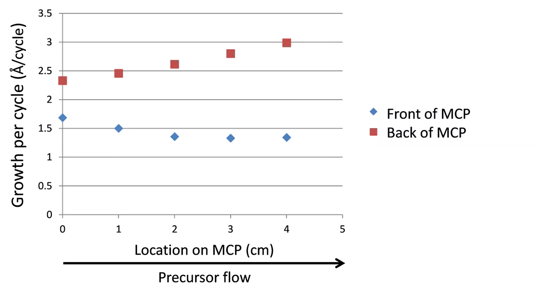
Early Attempt at Uniform MgO 70 cycles (EtCp)2Mg/H2O: 6-35-1.5-30 @200oC MgO measured on Si and MCP MCP located at centre of 9 x MCP holder 3.5 Growth per cycle ( /cycle) 3 2.5 2 Top of MCP Front of MCP Back of MCP 1.5 Bottom of MCP 1 0.5 0 0 1 2 3 4 5 Location on MCP (cm) Precursor flow Expected GPC 1.4 /cycle: Up to 2x higher GPC on back of MCP compared to front Non-uniformity in thickness will affect MCP gain
Optimized Process Substrate Layout: top 10 m dummy MCPs outlet inlet 20 m monitor MCPs 10 m dummy MCPs bottom Wedged holder with 9 x 9 holder for 53 mm MCPs 30 cycles (EtCp)2Mg/H2O: 2-120-1-60 @200oC
Measurement of MgO Thickness MgO thickness measured: On Si positioned beneath 9 MCP holder (8 x 8 Si) On front and back surfaces of MCP 5 points in each direction (2 x 2 MCP) Thickness measurement on MCP top top to bottom Inlet Centre Outlet inlet to outlet
Run 040214-1 MgO: (CpEt)2Mg + H2O Si along length of reactor, 9 x MCPs: 1 monitor (centre) Si std variation = 4%, GPC = 1.3 /cycle (direction: inlet-outlet) Si std variation = 13%, GPC = 1.5 /cycle (direction: top-bottom) Higher GPC on MCPs than on Si but good uniformity on both MCP surfaces Thickness on Si (8 x 8 Si) Thickness on Centre MCP (2 x 2 MCP) MCP front MCP back Precursor flow Precursor flow Precursor flow
Run 040214-2 MgO: (CpEt)2Mg + H2O Si along length of reactor, 9 x MCPs: inlet and outlet monitors Si std variation = 9.0%, GPC = 1.3 /cycle (direction: inlet-outlet) Si std variation = 9.8%, GPC = 1.5 /cycle (direction: top-bottom) Thickness on Inlet MCP (2 x 2 MCP) MCP front MCP back Thickness on Si (8 x 8 Si) Thickness on Outlet MCP (2 x 2 MCP) MCP front MCP back Precursor flow
All data: Runs 1 + 2 Reproducible MgO thickness on Si with 9 x MCPs Slight depletion in precursor at outer most point of holder (run 2) Decrease in MgO thickness from inlet to outlet but good uniformity across MCP top and bottom surfaces for all 3 monitor MCPs
Conclusions Uniform deposition on individual MCPs (front and back surfaces) located at inlet, centre and outlet positions Decrease in MgO thickness across reactor but precursor depletion only evident at outermost point on outlet MCP Challenges: Scaling to larger batches of 2 x 2 MCPs or 8 x 8 MCP Substrates require NiCr coated substrates for process optimization (need reflective surface for ellipsometry to measure thickness)
