Structural Analysis: Beam Deflection and Slope Calculation
In this structural analysis problem, we are tasked with determining the deflection and slopes at point B of a loaded beam. The calculations involve applying the moment-area method and the conjugate-beam method to create shear, bending moment diagrams, and the deflected curve. Theorems related to slopes and displacements in real and conjugate beams are also discussed. Detailed steps and formulas are provided to solve the problem effectively.

Download Presentation

Please find below an Image/Link to download the presentation.
The content on the website is provided AS IS for your information and personal use only. It may not be sold, licensed, or shared on other websites without obtaining consent from the author.If you encounter any issues during the download, it is possible that the publisher has removed the file from their server.
You are allowed to download the files provided on this website for personal or commercial use, subject to the condition that they are used lawfully. All files are the property of their respective owners.
The content on the website is provided AS IS for your information and personal use only. It may not be sold, licensed, or shared on other websites without obtaining consent from the author.
E N D
Presentation Transcript
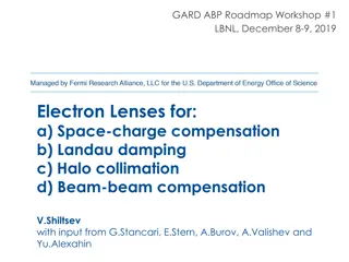
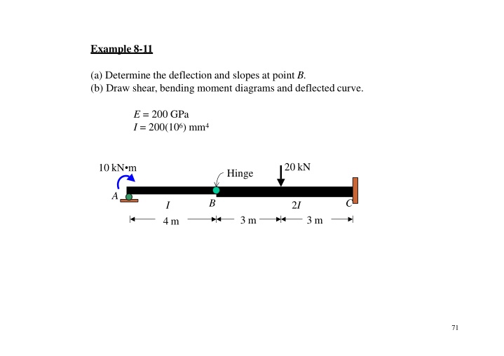
Example 8-11 (a) Determine the deflection and slopes at point B. (b) Draw shear, bending moment diagrams and deflected curve. E = 200 GPa I = 200(106) mm4 20 kN 10 kN m Hinge A B C 2I I 3 m 3 m 4 m 71
20 kN 10 kN m Hinge A B C 2I I 3 m 3 m 4 m 10 kN m 2.5 kN 0 20 kN 75 kN m 0 2.5kN 22.5kN 2.5kN V(kN) - x (m) - -2.5 -2.5 -22.5 -22.5 10 + M (kN m) x(m) - -7.5 -75 72
Moment-AreaMethod 20 kN Hinge 10 kN m A B C 2I I 3 m 3 m 4 m 10 + M (kN m) x (m) -7.5 - 10 EI M -75 x (m) diagram + EI 3.75 - EI 37.5 EI tangent C =horizontal C/B Deflected Curve B =tB/C BL = BR C/B tB/A A=tB /C+ tB /A B/A A 4 =tB / C + tB /A = B/ A B/ A BL A 4 73
3 m 3 m 4 m 11.25 5.25 BEI 10 Mdiagram EI EI C EI + x (m) A 20 EI - 50.625 75 . 3 EI 2 m EI 37.5 EI 24 3 4.5m 5 m = 5.625 + 11.25 + 50.265=67.5 67.5 = = = 0.00168rad B/C BR EI EI EI EI (200)(200) = 5.625(2)+ 11.25(4.5)+ 50.265(5) =315 EI EI 315 = t = = 7.875mm B/C B EI EI (200)(200) 315+(20)(24) = (EI 72.08 (200)(200) =tB /C+ tB / A ) 20 =72.08 EI 3 EI 4 = = 0.0018rad B/ A BL 4 EI B B = 7.875mm A C BR = 0.00168rad BL = 0.0018rad 74
Conjugate-Beam Method d 2 M = dV= w dx w dx2 d 2 =M d M = dx2 EI dx EI Or integrating, V = wdx M = [ wdx]dx = (M)dx = [ (M)dx]dx EI EI 5
Theorem 1: The slope at a point in the real beam is numerically equal to the shear at the corresponding point in the conjugate beam. Theorem 2: The displacement of a point in the real beam is numerically equal to the moment at the corresponding point in the conjugate beam. w A B L real beam M/EI A' B' L conjugate beam 6
Conjugate - BeamSupports Real Beam ConjugateBeam 1) V M =0 externalpin pin = 0 2) V M =0 external roller roller = 0 3) V M =0 internal pin hinge = 0 4) V M =0 internal roller hinge = 0 5) V M hinge internal roller 6) = 0 = 0 V =0 M =0 fixed free 7) V M free fixed 77
Real Beam Conjugate Beam hinge hinge hinge hinge 8
Example 8-10 The beam shown is subjected to a load P at its end. Determine the slope and displacement at C. EI is constant. P B C A C 2a a 9
= 0 B SOLUTION P = 0 C Real Beam A EI 2a a Mdiagram EI Pa2 Pa2 2EI Pa EI Pa3 E I V M =0 Hinge EI ConjugateBeam V M =0 V M 7Pa2 Pa2 6EI 3EI Pa2 3EI V diagram 2 2Pa 7Pa 2 3EI 6EI M diagram Pa3 80 3EI
2a 3 Conjugate Beam 1(2a) a 3 V B 2a B M C C B N B =0 A 0 =N B V B Pa2 R C Pa2 Pa R A EI 2EI E I MemberAB: MemberBC: 2Pa2 Pa2 Pa21 Fy =0: 3EI 2EI + R'C = 0 + MB =0: ( 2a) R'A(2a) = 0 + 3 EI 7Pa2 Pa2 R'A =3EI R'C=6EI Pa22 2Pa2 Pa2 Pa2 ( a)+ Fy =0: + MC =0: M'C + (a) =0 V 'B =0 + 2EI 3 3EI 3EI EI 2Pa2 Pa3 EI M'C= V 'B = 3EI 11
Example 8-11 Use the conjugate beam method for Determine the slope and deflection at points B of the beam shown in the figure. Take E = 200 GPa and I = 250(106) mm4. 10 kN A B 3 m 3 m 12
SOLUTION Real Beam Conjugate Beam 225 10 kN 30 kN m 3 m 3 m EI A B B A 3 m 3 m 30 45 EI 45 EI EI 10 kN 5 m V 10 10 (kN) V 10(3) =30 x (m) (kN m2) x (m) - M -45/EI -45/EI (kN m) x (m) M - (kN m3) x (m) -30 -225/EI Deflected Curve 83 B
Conjugate Beam 225 3 m 3 m EI B A =V' = 45 B B EI 30 45 45kN m2 45 EI = EI kN EI 5 m (200 106 )(250 10 6 m4) m2 V (kN m2) = -0.0009rad B x (m) - = M' = 225 -45/EI -45/EI M B B EI (kN m3) x (m) 225kN m3 = (200 106kN)(250 10 6m4) m2 -225/EI Real Beam B = -0.0045 m = -4.5mm B = 4.5 mm B = 0.0009 rad B 14
Example 8-12 Use the conjugate beam method for Determine the maximum deflection , the slope and deflection at points C of the beam shown in the figure. Take E = 200 GPa and I = 60(106) mm4. 8 kN A B C 9 m 3 m 15
SOLUTION Real Beam Conjugate Beam 81 27 8 kN EI 18/EI EI A B A B C C 9 m 3 m 9 m 3 m 45 63 2 kN 6 kN EI EI 6 m 10 m 18 M 63/EI (kN m) x (m) V 36/EI x (kN m2) + x (m) - V = = B A C -45/EI C M (kN m3) x (m) = max 86
maximum deflection slope and deflection at pointC x2 81 x 18 ( )( 9 2x EI )= 18/EI M C EI EI EI A A M x C V C 9 m V =0 45 45 x 3 EI EI 3 m x2 EI 45 EI 45 EI 81 EI Fy =0: Fy= 0: + =0 + + + V' =0 C V' =36 x = 6.71m C EI + Mx =6.71= 0: Note : V C is the same value from previously obtained V diagram. (6.71)26.71 EI 45 EI M' )+ (6.71) =0 ( + MC =0: 3 M'= 201.246 M ' 81 (3) +45 (9) =0 C EI EI EI = M'= 201.246 M' = 162 max C EI EI 17
201.25kN m3 = 201.25 = EI = M' max kN m2)(60 10 6m4) (200 106 max = -0.01677 m = -16.77mm 81kN m2 =81= =V'C C kN m2)(60 10 6 m4) EI (200 106 C = 0.003 rad 162 kN m3 162 = M 'C = EI= C kN m2 (200 106 )(60 10 6 m4) C = -0.0135 m = -13.35mm C = 13.35 mm B A C = 0.003 rad max = 16.77 mmC 18