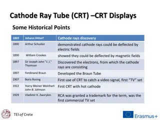
Cathode Ray Tubes (CRT) in Oscilloscopes

Cathode Ray Tubes (CRTs) are key components in oscilloscopes, modulating and accelerating electron beams to create images of electrical waveforms, radar targets, and more. Unlike TVs, CRTs in oscilloscopes use electrostatic deflection for precise beam control. The electron gun assembly consists of a cathode, control grid, focusing anode, and accelerating anode to generate a focused electron beam. Control grids regulate electron emission, while accelerating anodes enhance beam velocity. Explore the intricate workings of CRT technology for oscilloscopes in detail.

Download Presentation

Please find below an Image/Link to download the presentation.
The content on the website is provided AS IS for your information and personal use only. It may not be sold, licensed, or shared on other websites without obtaining consent from the author.If you encounter any issues during the download, it is possible that the publisher has removed the file from their server.
You are allowed to download the files provided on this website for personal or commercial use, subject to the condition that they are used lawfully. All files are the property of their respective owners.
The content on the website is provided AS IS for your information and personal use only. It may not be sold, licensed, or shared on other websites without obtaining consent from the author.
E N D
Presentation Transcript
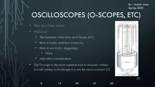
CRT iscalled the heartof oscilloscope. It modulates, accelerates, beam(s) onto thescreen tocreate the images. The images may represent electrical waveforms, pictures (television, computer monitor), radar targets, orothers. The CRT uses an evacuated glass envelope which is large, deep (i.e. long from front screen face to rearend), fairly heavy, and relatively fragile. and deflects electron
In oscilloscope CRTs, electrostatic deflection is used, rather than the magnetic deflection commonly used with televisionand other large CRTs. The beam is deflected horizontally by applying an electric field between a pair of plates to its left and right, and vertically by applying an electric field to platesaboveand below. Televisions use magnetic rather than electrostatic deflection because the deflection plates obstruct the beam when the deflection angle is as large as is required fortubes thatarerelativelyshort fortheirsize.
The electron gun assembly consists of an indirectly heated cathode, a control grid surrounding the cathode, a focusing anodeand anacceleratinganode. The sole function of the electron gun assembly is to provide a focused electron beam which is accelerated towardsthe phosphorscreen. The cathode is a nickel cylinder coated with an oxide coating and emits plentyof electrons, when heated. The emitting surface of the cathode should be as small as possible, theoreticallyapoint.
Rate of emission of electrons or say the intensity of electron beam depends on the cathode current, which can be controlled by the control grid in a mannersimilartoaconventionalvacuum tube. The control grid is a metal cylinder covered at one end butwith asmall hole in thecover. The grid is kept at negative potential (variable) with respect to cathode and its function is to vary the electron emission and so the brilliancy of the spoton thephosphorscreen.
The hole in the grid is provided to allow passage for electrons through it and concentrate the beam of electronsalong theaxisof tube. Electron beam comes out from the control grid through a small hole in it and enters a pre- accelerating anode, which is a hollow cylinder in shape and is at a potential of few hundred volts more positive than the cathode so as to accelerate theelectron beam in theelectric field. This accelerated beam would be scattered now becauseof variations in energy and would producea broad ill-defined spoton thescreen.
This electron beam is focused on the screen by an electrostatic lens consisting of two more cylindrical anodes called the focusing anode and accelerating anodeapart from the pre-accelerating anode. The focusing and accelerating anodes may be open or close at both ends and if covered, holes must be provided in the anode cover for the passage of electrons. The function of these anodes is to concentrate and focus the beam on the screen and also to accelerate thespeed of electrons.
Electron beam, after leaving the electron gun, passes through the twopairsof deflection pates. One pair of deflection plates is mounted vertically and deflects the beam in horizontal or X-direction and so called the horizontal or X-plates and the other pair is mounted horizontally and deflects the beam in vertical or Y-direction and called the vertical orY-plates. These plates are to deflect the beam according to the voltage applied across them. For example if a constant pd is applied to the set of Y-plates, the electron beam will be deflected upward if the upperplate is positive.
In case the lower plate is positive then the beam will be deflected downward. Similarly if a constant pd is applied to the set of X-plates, the electron beam will be deflected to the left or right of the tube axis according to the condition whether the left or rightplate is positive. When a sinusoidal voltage is applied to Y-plates, the beam will be moved up and down according to thevariationof platepotential.
Various phosphors are available depending upon the needsof the measurementordisplayapplication. The brightness, color, illumination depends upon the type of phosphor used on the CRTscreen. Phosphors are available with persistence ranging from less thanone microsecond toseveral seconds. For visual observation of brief transient events, a long persistence phosphor may be desirable. For events which are fast and repetitive, or high frequency, a short-persistencephosphor isgenerallypreferable. and persistence of the
The whole assembly is protected in a conical highly evacuated glass housing through suitable supports. The innerwalls of CRT between neck and screen are usually coated with a conducting material known as aquadag and this coating is electrically connected to thecathode. The coating is provided in order to accelerate the electron beam after passing between the deflecting plates and to collect the electrons produced by secondary emission when electron beam strikes thescreen.
Thus the negative equilibriumof screen is maintained. coating charge prevents the the screen formation and of of on state
Most oscilloscopes have a graticule as part of the visual display, to facilitate measurements. The graticule may be permanently marked inside the face of the CRT, or it may be a transparent external plate madeof glass oracrylicplastic. An internal graticule eliminates parallax error, but cannot be changed to accommodate different types of measurements. Oscilloscopes commonly provide a means for the graticule to be illuminated from the side, which improves itsvisibility. Horizontal and vertical marks are marked on the screen of the CRT to provideuseracorrect measurement. These marks, usually in rectangular form, are called graticule.
There are two popular techniques for producing color displays with a CRT are: 1. Beam-penetration method 2. Shadow-mask method Beam penetration method: It is a cheaper method and is used in Vector scan displays.
In this method the inside section of CRT is coated with red (outer layer) and green (inner layer) phosphors. If the electrons are slow they penetrate only the outer layer thus emitting red light, and if the electrons are moving fast they penetrate the outer layerand the inner layer. The electrons speed is also adjusted in such a way that by combination of red and green, orange and yellowcolorarealsoproduced. The limitation of this method is that only four colors can be displayed in the screen. Since we have only fourcolors thequalityof image isdiminished.
It is used basically in Raster scan displays (color TV). In this method, the screen has 3 phosphor colored dots which emits colors red, green and blue in a single pixel position. We use 3 electron guns for emitting colors red, green and blue. Now, three electrons are fired from these guns simultaneously and when they pass through shadow mask they form a phosphor dot triangle of colors red, greenand blue in screen. This triangle is actually a pixel in the screen. The color of this pixel can be controlled by controlling the intensityof theelectron beams. Also, by controlling the intensity of electron beams we can produce other colors which are combinations of colors red, greenand blue.


.")
.")