Status of Belle II SVD and PXD Detectors Workshop

1
Cluster-shape based improvement of spatial resolution for the
Belle II DEPFET pixel detector
Peter Kody
š
,
Charles University in Prague


C
h
a
r
l
e
s
U
n
i
v
e
r
s
i
t
y
P
r
a
g
u
e
The 6th Belle II PXD/SVD workshop, status of the Belle II SVD and PXD detectors
1-3 October 2014, Pisa (Italy)
F2F Tracking meeting in Pisa, 29.-30.9.2014
2
DEPFET sensors at Belle II
Peter
Kody
š,
The 6th Belle II PXD/SVD
, 1-3 October 2014, Pisa
3
•
Full Geant4 simulation
in the basf2 (software framework for the Belle II)
•
There are
five basic types of clusters
for four different pitch in v
direction: single, double and triple pixel clusters, rest of symmetrical
and nonsymmetrical clusters.
•
In Belle II geometry for particles shot of 0.05 – 3.0 GeV electrons and
positrons in uniformly distributed directions from the interaction point
and in range theta 17 – 150 deg
•
In
Belle II:
25 % form single-pixel clusters, 15 % form 2-pixel clusters
along the R-phi coordinate, and 26 % along the z-coordinate.
12 %
form non-symmetric "L"-shaped three-pixel clusters
, 16 % form larger
non-symmetrical clusters, and rest 6 % form symmetrical clusters (like
2x2 clusters).
Using cluster shape to improve of hit position
Peter
Kody
š,
The 6th Belle II PXD/SVD
, 1-3 October 2014, Pisa
4
•
For
single-pixel clusters
, the obvious hit position estimate is the center
of the pixel.
•
For
larger clusters
, hit position is estimated separately for the u- and v-
coordinates, using
center-of-gravity
estimates for clusters size 2 and
the analog head-tail method
for size 3 and more. Generally, the
average resolution is best for small clusters of size 2 and 3.
•
For single-pixel clusters, hit position uncertainty is given by the area
where a given energy deposition is mostly contained within the single
pixel - it therefore depends on
pixel charge
and
clustering threshold.
•
With particles arriving at different (and unknown) directions, the
standard eta-correction algorithms are not usable. Therefore, simple
bias-correcting
methods
for center-of-gravity and head-tail estimates
are desirable, that would only use
measurable quantities
to correct for
bias.
Using cluster shape to improve of hit position
Peter
Kody
š,
The 6th Belle II PXD/SVD
, 1-3 October 2014, Pisa
5
•
The 3-pixel “L”-shaped clusters
are the simplest
and most common case where such a bias
correction would be desirable.
•
For these clusters, the center-of-gravity estimate
is
biased by about 10% of pixel size
, comparable
to the typical RMS error of the position estimate.
Therefore,
correction of the bias highly desirable
.
•
We show that adding a fixed (pixel noise
dependent) charge to the pixel with zero signal in
the 2x2 matrix can significantly improve the
center-of-gravity estimate of hit position for such
clusters.
Adding the fourth pixel with the signal of
1.3 x ENC
improved position RMS error from 7.4
microns to 4.7 microns in R-phi, and reduced
position from 5 to 2 microns.
Using cluster shape to improve of hit position
Residual plot of “L” shape in one orientation
before (left) and after (right) correction
Residual plot of “L” shape in all orientation
before (left) and after (right) correction
Peter
Kody
š,
The 6th Belle II PXD/SVD
, 1-3 October 2014, Pisa
Cut of incident angle range in r-phi
6
Using cluster shape to improve of hit position
Fractions of cluster shape types
for different
clustering cuts.
Table for
hit position bias
reconstructed from
“L”-shaped clusters
before and after correction
for different clustering cuts
Table for
RMS error
reconstructed from
“L”-
shaped clusters
before and after correction for
different clustering cuts
clustering cuts 3xENC
(default)
Peter
Kody
š,
The 6th Belle II PXD/SVD
, 1-3 October 2014, Pisa
7
•
1 ADU = 200 e
-
•
r-phi =
-10 .. +35 deg
, theta 17 – 150 deg
observe big bias
Using cluster correction in detail…
Example of “L” cluster shape with signals
Typical PXD cluster charge plot in ADU in Belle II
Peter
Kody
š,
The 6th Belle II PXD/SVD
, 1-3 October 2014, Pisa
±noise
8
Residual plot of “L” shape in one orientation
before (left) and after (right) correction
Residual plot of “L” shape in all orientation
before (left) and after (right) correction
Peter
Kody
š,
The 6th Belle II PXD/SVD
, 1-3 October 2014, Pisa
Cut of incident angle range in r-phi
Residual plot
before (left) and after (right) correction
•
u (r-phi) direction: -10 .. +35 deg
•
V (theta) change: -10 .. +10 deg
•
Than bias is on both direction and correction works better
Using cluster correction in detail…
9
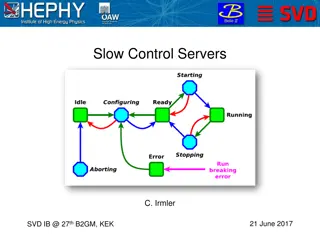
•
Improvement of hit position reconstruction
is important for vertexing
performance and new physics searches.
•
Realistic estimates of hit position uncertainties
and
correction of
reconstruction bias
is equally important.
•
We have shown that the most important reconstruction biases in
small “L”-shaped clusters can be easily
corrected by adding a
constant charge
in the missing pixel.
•
This efficiently
corrects
for center-of-gravity
bias
and
improves
the
distribution of residuals
.
Conclusion & plan
•
General algorithm
for error estimation and bias corrections for “L”
cluster shape independent of Belle II geometry is on process and
would be soon
•
Angle dependent correction and error estimation
is under study and
would be soon
•
Improvement
of error estimation to more realistic values
•
In-pixel
analysis and
validation
plots
Peter
Kody
š,
The 6th Belle II PXD/SVD
, 1-3 October 2014, Pisa
10
Peter
Kody
š,
The 6th Belle II PXD/SVD
, 1-3 October 2014, Pisa
Position of source
Conclusion & plan
11
Conclusion & plan
Peter
Kody
š,
The 6th Belle II PXD/SVD
, 1-3 October 2014, Pisa
Different pixel size vs. angle
50 x
55
x 75
m
v: 20.1 / 36.6 / 55.7 deg
50 x
60
x 75
m
v: 21.8 / 38.7 / 58.0 deg
50 x
70
x 75
m
v: 25.0 / 43.0 / 61.8 deg
50 x
85
x 75
m
v: 29.5 / 48.7 / 66.2 deg
2.96
1.10
0.59
1.63
Space angle [sr]
u
50
m
: 18.4 / 33.7 / 53.1 deg
47.1%
17.5%
9.4%
25.9%
12
Thank you for your attention!
Conclusion & plan
Peter
Kody
š,
The 6th Belle II PXD/SVD
, 1-3 October 2014, Pisa
Angle vs. in-pixel position
50 x 55 x 75
m
Belle II collaborators met in Pisa, Italy for the 6th Belle II PXD/SVD workshop. The discussions focused on the status and improvements of the Belle II SVD and PXD detectors, including cluster-shape based methods to enhance spatial resolution. Presentations by experts from Charles University in Prague highlighted advancements in detector technology for high-precision tracking applications.

Download Presentation

Please find below an Image/Link to download the presentation.
The content on the website is provided AS IS for your information and personal use only. It may not be sold, licensed, or shared on other websites without obtaining consent from the author.If you encounter any issues during the download, it is possible that the publisher has removed the file from their server.
You are allowed to download the files provided on this website for personal or commercial use, subject to the condition that they are used lawfully. All files are the property of their respective owners.
The content on the website is provided AS IS for your information and personal use only. It may not be sold, licensed, or shared on other websites without obtaining consent from the author.
E N D
Presentation Transcript
The 6th Belle II PXD/SVD workshop, status of the Belle II SVD and PXD detectors 1-3 October 2014, Pisa (Italy) F2F Tracking meeting in Pisa, 29.-30.9.2014 Charles University Prague Cluster-shape based improvement of spatial resolution for the Belle II DEPFET pixel detector Peter Kody , Charles University in Prague 1
DEPFET sensors at Belle II Inner Layer 8 75 microns 90 mm 44.8 x 12.5 mm261.44 x 12.5 mm2 55,60 x 50 m2 3.072 x 10⁶ 50 kHz Outer Layer 12 75 microns 123 mm Modules Thickness Length Sensitive Pixel Size Pixels Frame Rate 70,85 x 50 m2 4.608 x 10⁶ 50 kHz 2 Peter Kody , The 6th Belle II PXD/SVD , 1-3 October 2014, Pisa
Using cluster shape to improve of hit position Full Geant4 simulation in the basf2 (software framework for the Belle II) There are five basic types of clusters for four different pitch in v direction: single, double and triple pixel clusters, rest of symmetrical and nonsymmetrical clusters. In Belle II geometry for particles shot of 0.05 3.0 GeV electrons and positrons in uniformly distributed directions from the interaction point and in range theta 17 150 deg In Belle II: 25 % form single-pixel clusters, 15 % form 2-pixel clusters along the R-phi coordinate, and 26 % along the z-coordinate. 12 % form non-symmetric "L"-shaped three-pixel clusters, 16 % form larger non-symmetrical clusters, and rest 6 % form symmetrical clusters (like 2x2 clusters). 1-pixel 2-pixels 3-pixels non-symmetrical symmetrical Categorization of cluster shapes 3 Peter Kody , The 6th Belle II PXD/SVD , 1-3 October 2014, Pisa
Using cluster shape to improve of hit position For single-pixel clusters, the obvious hit position estimate is the center of the pixel. For larger clusters, hit position is estimated separately for the u- and v- coordinates, using center-of-gravity estimates for clusters size 2 and the analog head-tail method for size 3 and more. Generally, the average resolution is best for small clusters of size 2 and 3. For single-pixel clusters, hit position uncertainty is given by the area where a given energy deposition is mostly contained within the single pixel - it therefore depends on pixel charge and clustering threshold. With particles arriving at different (and unknown) directions, the standard eta-correction algorithms are not usable. Therefore, simple bias-correcting methods for center-of-gravity and head-tail estimates are desirable, that would only use measurable quantities to correct for bias. 4 Peter Kody , The 6th Belle II PXD/SVD , 1-3 October 2014, Pisa
Using cluster shape to improve of hit position The 3-pixel L -shaped clusters are the simplest and most common case where such a bias correction would be desirable. For these clusters, the center-of-gravity estimate is biased by about 10% of pixel size, comparable to the typical RMS error of the position estimate. Therefore, correction of the bias highly desirable. We show that adding a fixed (pixel noise dependent) charge to the pixel with zero signal in the 2x2 matrix can significantly improve the center-of-gravity estimate of hit position for such clusters. Adding the fourth pixel with the signal of 1.3 x ENC improved position RMS error from 7.4 microns to 4.7 microns in R-phi, and reduced position from 5 to 2 microns. Cut of incident angle range in r-phi Residual plot of L shape in one orientation before (left) and after (right) correction Residual plot of L shape in all orientation before (left) and after (right) correction 5 Peter Kody , The 6th Belle II PXD/SVD , 1-3 October 2014, Pisa
Using cluster shape to improve of hit position Table for hit position bias reconstructed from L -shaped clusters before and after correction for different clustering cuts RMS of residual plot for "L" clustershape in microns Fraction of Cluster Type for Different Cut of Cluster Cluster cut [ENC] No correction R-phi No correction Z Correction R-phi Correction Z 2 3 4 5 6 100 ] [% 5.8 4.0 1.9 -0.6 5.7 3.4 2.0 -1.3 5.6 3.1 2.0 -1.4 5.6 2.9 1.8 -1.9 5.5 3.0 90 Fraction 80 70 60 50 clustering cuts 3xENC (default) 40 30 RMS of residual plot for "L" cluster shape in microns 20 Cluster cut [ENC] No correction R-phi No correction Z CorrectionR-phi CorrectionZ 2 3 4 5 6 10 7.6 7.3 4.9 6.6 7.4 7.6 4.7 7.4 7.4 8.0 4.7 8.0 7.4 9.2 4.7 9.6 7.5 10.1 0 2.0 3.0 4.0 5.0 6.0 Cluster Cut in S/N 1 2u 2v 3 nonSymRest SymRest Fractions of cluster shape types for different clustering cuts. Fractions of cluster shape types for different clustering cuts. Residuals for hit position reconstructed from L -shaped clusters before and after correction, tables for hit position bias and RMS error for different clustering cuts Table for RMS error reconstructed from L - shaped clusters before and after correction for different clustering cuts 6 Peter Kody , The 6th Belle II PXD/SVD , 1-3 October 2014, Pisa
Using cluster correction in detail 1 ADU = 200 e- r-phi = -10 .. +35 deg, theta 17 150 deg observe big bias 1 ADU = 200 e- Electrons ADU S/N 300 1.5 cluster charge MPV 6400 32 25 seed cut 1000 5 cluster charge cut 1600 8 20 25+13+9 cluster shape cut 600 3 adding charge to L shape 1200 6 +6 15 10 noise 5 cluster shape cut 0 Example of L cluster shape with signals Typical PXD cluster charge plot in ADU in Belle II 7 Peter Kody , The 6th Belle II PXD/SVD , 1-3 October 2014, Pisa
Using cluster correction in detail u (r-phi) direction: -10 .. +35 deg V (theta) change: -10 .. +10 deg Than bias is on both direction and correction works better Cut of incident angle range in r-phi Residual plot of L shape in one orientation before (left) and after (right) correction Residual plot before (left) and after (right) correction Residual plot of L shape in all orientation before (left) and after (right) correction 8 Peter Kody , The 6th Belle II PXD/SVD , 1-3 October 2014, Pisa
Conclusion & plan Improvement of hit position reconstruction is important for vertexing performance and new physics searches. Realistic estimates of hit position uncertainties and correction of reconstruction bias is equally important. We have shown that the most important reconstruction biases in small L -shaped clusters can be easily corrected by adding a constant charge in the missing pixel. This efficiently corrects for center-of-gravity bias and improves the distribution of residuals. General algorithm for error estimation and bias corrections for L cluster shape independent of Belle II geometry is on process and would be soon Angle dependent correction and error estimation is under study and would be soon Improvement of error estimation to more realistic values In-pixel analysis and validation plots 9 Peter Kody , The 6th Belle II PXD/SVD , 1-3 October 2014, Pisa
Conclusion & plan Position of source 10 Peter Kody , The 6th Belle II PXD/SVD , 1-3 October 2014, Pisa
Conclusion & plan 1.100.59 1.63 Different pixel size vs. angle 50 x 55 x 75 m v: 20.1 / 36.6 / 55.7 deg 2.96 Space angle [sr] 50 x 60 x 75 m v: 21.8 / 38.7 / 58.0 deg u 50 m : 18.4 / 33.7 / 53.1 deg 50 x 70 x 75 m v: 25.0 / 43.0 / 61.8 deg 17.5% 9.4% 25.9% 50 x 85 x 75 m v: 29.5 / 48.7 / 66.2 deg 47.1% 11 Peter Kody , The 6th Belle II PXD/SVD , 1-3 October 2014, Pisa
Conclusion & plan Angle vs. in-pixel position 50 x 55 x 75 m Thank you for your attention! 12 Peter Kody , The 6th Belle II PXD/SVD , 1-3 October 2014, Pisa