Ship Drive Train and Power Systems

7
.
2
S
h
i
p
D
r
i
v
e
T
r
a
i
n
a
n
d
P
o
w
e
r

S
h
i
p
D
r
i
v
e
T
r
a
i
n
S
y
s
t
e
m


Engine
Reduction
Gear
Bearing
Seals

Screw
Strut


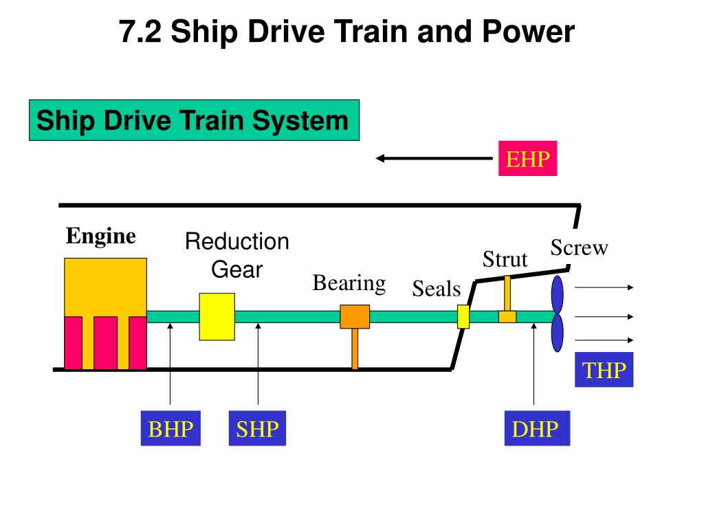
Brake Horsepower (BHP)
- Power output at the shaft coming out of the engine before
the reduction gears


Engine
R
e
d
u
c
t
i
o
n
G
e
a
r
Bearing
Seals

Screw
Strut

SHP

DHP

THP


EHP

S
h
i
p
D
r
i
v
e
T
r
a
i
n
a
n
d
P
o
w
e
r
Shaft Horsepower (SHP)
- Power output at the shaft coming out of the reduction gears
Engine
R
e
d
u
c
t
i
o
n
G
e
a
r
Bearing
Seals
Screw
Strut
BHP
SHP
DHP
THP
EHP
S
h
i
p
D
r
i
v
e
T
r
a
i
n
a
n
d
P
o
w
e
r
Engine
R
e
d
u
c
t
i
o
n
G
e
a
r
Bearing
Seals
Screw
Strut
BHP
SHP
DHP
THP
EHP
Delivered Horsepower (DHP)
- Power delivered to the propeller
- DHP=SHP – losses in shafting, shaft bearings and seals
S
h
i
p
D
r
i
v
e
T
r
a
i
n
a
n
d
P
o
w
e
r
Engine
R
e
d
u
c
t
i
o
n
G
e
a
r
Bearing
Seals
Screw
Strut
BHP
SHP
DHP
THP
EHP
Thrust Horsepower (THP)
- Power created by the screw/propeller
- THP=DHP – Propeller losses
- THP is the end result of all HP losses along the drive train
S
h
i
p
D
r
i
v
e
T
r
a
i
n
a
n
d
P
o
w
e
r
Relative Magnitudes
BHP
>
SHP
>
DHP
>
THP >
EHP
The reverse relationship can NEVER be true because there is
ALWAYS some loss of power due to heat, friction, and sound
S
h
i
p
D
r
i
v
e
T
r
a
i
n
a
n
d
P
o
w
e
r
7.3 Effective Horsepower (EHP)
The power required to move the ship hull at a given speed
in the absence of propeller action
EHP is not related to Power Train System
The required EHP varies depending on the vessel’s speed.
Effective Horsepower (EHP)
EHP Calculation
Effective Horsepower (EHP)
The loss in HP along the drive train can be related in terms of
EFFICIENCY,
or
“
”
-
Highlights the loss of horsepower from the engine to the shaft as a result of
the reduction gears
-
SHP is always less than BHP
7.4 Propulsion Efficiency
Shaft Transmission Efficiency
shaft
= DHP
SHP
-
The loss of horsepower from the reduction gears to the propeller due to the
bearings and seals that support and seal the drive shaft
- The loss of power is converted to heat and sound due to friction
Delivered Horsepower
Shaft Horsepower
Propulsion Efficiency
Hull Efficiency
-
Hull efficiency changes due to hull-propeller interactions.
-
Well-designed ship :
-
Poorly-designed ship :
-
Flow is not smooth.
-
THP is reduced.
- High THP is needed
to get designed speed
.
Propulsion Efficiency
Effective Horsepower
Thrust Horsepower
(The loss of power will be a function of the hull design)
Screw
Propeller Efficiency
SHP
DHP
THP
EHP
Propulsion Efficiency
Propulsive
Efficiency (Coefficient (PC))
P
= EHP
SHP
-
Combines the losses due to the bearings, guides, and the propeller efficiency
-
Compares the output from the reduction gears to the required towing HP
-
Commonly ranges from 55 - 75%
-
Once
p
is found, can try different power plants, gearing, and fuel efficiencies
Effective Horsepower
Shaft Horsepower
Propulsion Efficiency
Example
:
Through modeling of a ship’s design, it is found that the towing
horsepower required to maintain a speed of 20 knots is 23,500 HP. Assuming
a propulsive efficiency of 68%, what is the expected required power output
from the reduction gears (shaft horsepower)?
Solution:
SHP = 34,559 HP
SHP = 23,500 HP / .68
Example Problem
What are the various components, HPs,
s
and common values for
s for the drawing
below?
_
HP
_
HP
_
HP
_
HP
_
HP
gear
=_HP/_HP
(~__-__%)
shaft
=_HP/_HP
(~__-__%)
prop
=_HP/_HP
(~__-__%)
H
=_HP/_HP
P
=PC=_HP/_HP
(~__-__%)
Example Answer
What are the various components, HPs,
s
and common values for
s for the drawing
below?
Prime
Mover
Reduction
Gear
Shafting &
Bearings
Propeller
Hull
BHP
SHP
DHP
THP
EHP
gear
=SHP/BHP
(~98-99%)
shaft
=DHP/SHP
(~97-98%)
prop
=THP/DHP
(~70-75%)
H
=EHP/THP
P
=PC=EHP/SHP
(~55-75%)
7
.
5
T
o
t
a
l
H
u
l
l
R
e
s
i
s
t
a
n
c
e
Total Hull Resistance
(R
T
)
The force that the ship experiences opposite to the motion of
the ship as it moves.
EHP Calculation
Coefficient of Total Hull Resistance
- Non-dimensional value of total resistance
T
o
t
a
l
H
u
l
l
R
e
s
i
s
t
a
n
c
e
Coefficient of Total Hull Resistance
-
Total Resistance of full scale ship
can be determined using
T
o
t
a
l
H
u
l
l
R
e
s
i
s
t
a
n
c
e
Relation of Total Resistance Coefficient and Speed
T
o
t
a
l
H
u
l
l
R
e
s
i
s
t
a
n
c
e
Resistance values, denoted by
R
, are
dimensional
values
R
T
= Total hull resistance is the sum of all resistance
R
T
= R
AA
+ R
W
+ R
V
R
AA
= Resistance caused by calm air on the superstructure
R
W
= Resistance due to waves caused by the ship
- A function of beam to length ratio, displacement, hull shape &
Froude number (ship length & speed)
R
V
= Viscous resistance (frictional resistance of water)
- A function of viscosity of water, speed, and wetted surface
area of ship
7
.
6
T
o
t
a
l
H
u
l
l
R
e
s
i
s
t
a
n
c
e
For pilots, this is subsonic, incompressible drag
Total Resistance and Relative Magnitude of Components
Viscous
Air Resistance
Wave-making
Speed (kts)
Resistance (lb)
-
Low speed :
Viscous R
-
Higher speed :
Wave-making R
-
Hump (Hollow) : location is
function of ship length and speed
.
Hump
Hollow
T
o
t
a
l
H
u
l
l
R
e
s
i
s
t
a
n
c
e
C
o
m
p
o
n
e
n
t
s
o
f
T
o
t
a
l
R
e
s
i
s
t
a
n
c
e
Viscous Resistance
- Resistance due to the
viscous stresses
that the fluid exerts
on the hull.
( due to friction of the water against the surface of the ship)
-
Viscosity, ship’s velocity, wetted surface area
of ship
generally affect the viscous resistance.
Wave-Making Resistance
- Resistance
caused by waves generated by the motion of the ship
- Wave-making resistance is affected by
beam to length ratio,
displacement, shape of hull, Froude number (ship length &
speed)
Air Resistance
- Resistance
caused by the flow of air over the ship with no
wind present
- Air resistance is affected by projected area, shape of the ship
above the water line, wind velocity and direction
- Typically 4 ~ 8 % of the total resistance
Dimensionless Coefficients
C
T
= Coefficient of
total hull resistance
C
T
= C
V
+ C
W
C
V
= Coefficient of
viscous resistance
over the wetted area of
the ship as it moves through the water
- C
F
=
Tangential component
(skin resistance)
- KC
F
=
Normal component
(viscous pressure drag)
C
W
= Coefficient of
wave-making
resistance
C
o
m
p
o
n
e
n
t
s
o
f
T
o
t
a
l
R
e
s
i
s
t
a
n
c
e
C
o
e
f
f
i
c
i
e
n
t
o
f
V
i
s
c
o
u
s
R
e
s
i
s
t
a
n
c
e
(
C
V
)
V
i
s
c
o
u
s
F
l
o
w
a
r
o
u
n
d
a
s
h
i
p
Real ship : Turbulent flow exists near the bow.
Model ship :
Studs or sand strips
are attached at the bow
to create the turbulent flow.
C
o
e
f
f
i
c
i
e
n
t
s
o
f
V
i
s
c
o
u
s
R
e
s
i
s
t
a
n
c
e
- Non-dimensional quantity of viscous resistance
- It consists of tangential and normal components.
CF=tangential (skin friction) component of viscous resistance
KCF=normal (viscous pressure/form drag) component of viscous friction
T
a
n
g
e
n
t
i
a
l
C
o
m
p
o
n
e
n
t
:
C
F
- Tangential stress is parallel to ship’s hull and causes
a net force opposing the motion ;
Skin Friction
- It is assumed can be obtained from the experimental
data of flat plate.
C
o
e
f
f
i
c
i
e
n
t
o
f
V
i
s
c
o
u
s
R
e
s
i
s
t
a
n
c
e
(
C
V
)
Semi-empirical
equation
C
o
e
f
f
i
c
i
e
n
t
o
f
V
i
s
c
o
u
s
R
e
s
i
s
t
a
n
c
e
(
C
V
)
Boundary Layer Separation Resistance
Viscous Pressure/Form Drag
–
Laminar Flow
–
Turbulent Flow
•
Boundary Layer
Bernoulli’s Equation:
p/
+V²/2+gz=constant
High Velocity/
Low Pressure
Low Velocity/
High Pressure
Low Velocity/
High Pressure
Turbulent
Wake
Boundary Layer
Boundary Layer Separation
High Velocity/
Low Pressure
Low Velocity/
High Pressure
C
o
e
f
f
i
c
i
e
n
t
o
f
V
i
s
c
o
u
s
R
e
s
i
s
t
a
n
c
e
(
C
V
)
T
a
n
g
e
n
t
i
a
l
C
o
m
p
o
n
e
n
t
:
C
F
- Relation between viscous flow and Reynolds number
·
Laminar flow
:
In laminar flow, the fluid flows in layers
in an orderly fashion. The layers do not mix transversely
but slide over one another.
· Turbulent flow
:
In turbulent flow, the flow is chaotic and
mixed transversely.
Flow over
flat plate
C
o
e
f
f
i
c
i
e
n
t
o
f
V
i
s
c
o
u
s
R
e
s
i
s
t
a
n
c
e
(
C
V
)
N
o
r
m
a
l
C
o
m
p
o
n
e
n
t
:
K
C
F
- Normal component causes a pressure distribution along the
underwater hull form of ship
- A high pressure is formed in the forward direction opposing
the motion and a lower pressure is formed aft.
-
Normal component generates the eddy behind the hull
.
- It is affected by hull shape.
Fuller shape ship has larger normal component than slender
ship
.
Full ship
Slender ship
large eddy
small eddy
C
o
e
f
f
i
c
i
e
n
t
o
f
V
i
s
c
o
u
s
R
e
s
i
s
t
a
n
c
e
(
C
V
)
N
o
r
m
a
l
C
o
m
p
o
n
e
n
t
:
K
C
F
- It is calculated by the product of
Skin Friction
with
Form Factor.
C
o
e
f
f
i
c
i
e
n
t
o
f
V
i
s
c
o
u
s
R
e
s
i
s
t
a
n
c
e
(
C
V
)
K= Form Factor
C
o
e
f
f
i
c
i
e
n
t
o
f
V
i
s
c
o
u
s
R
e
s
i
s
t
a
n
c
e
(
C
V
)
R
e
d
u
c
i
n
g
t
h
e
V
i
s
c
o
u
s
R
e
s
i
s
t
a
n
c
e
C
o
e
f
f
.
-
Method :
Increase L while keeping the submerged volume constant
1)
Form Factor K
Normal component KC
F
Slender hull is favorable. ( Slender hull form will create
a smaller pressure difference between bow and stern.)
2)
Reynolds No.
Rn
CF
KC
F
C
o
e
f
f
i
c
i
e
n
t
o
f
V
i
s
c
o
u
s
R
e
s
i
s
t
a
n
c
e
(
C
V
)
Froude Number
F
n
The Froude Number (inertia force/gravity force) is another dimensionless value
derived from model testing:
...Velocity is typically expressed in Knots (1 knot = 1.688ft/s)
Typical Wave Patterns are made up of
TRANSVERSE
and
DIVERGENT
waves
Coefficient of Wave Resistance
C
W
Coefficient of Wave Resistance
C
W
T
r
a
n
s
v
e
r
s
e
w
a
v
e
S
y
s
t
e
m
•
It travels at approximately
the same speed as the ship
.
•
At slow speed, several crests exist along the ship length
because the wave lengths are smaller than the ship length.
•
As the ship speeds up, the length of the transverse wave
increases.
•
When the transverse wave length approaches the ship length
,
the wave making resistance increases very rapidly
.
T
h
i
s
i
s
t
h
e
m
a
i
n
r
e
a
s
o
n
f
o
r
t
h
e
d
r
a
m
a
t
i
c
i
n
c
r
e
a
s
e
i
n
T
o
t
a
l
R
e
s
i
s
t
a
n
c
e
a
s
s
p
e
e
d
i
n
c
r
e
a
s
e
s
.
Coefficient of Wave Resistance
C
W
T
r
a
n
s
v
e
r
s
e
w
a
v
e
S
y
s
t
e
m
Vs < Hull Speed
Vs
Hull Speed
Hull Speed
:
speed at which the transverse wave length equals
the ship length.
(Wavemaking resistance drastically increases above hull speed)
Coefficient of Wave Resistance
C
W
D
i
v
e
r
g
e
n
t
W
a
v
e
S
y
s
t
e
m
•
It consists of
Bow and Stern Waves
.
•
Interaction of the bow and stern waves create the
Hollow or
Hump
on the resistance curve.
H
u
m
p
:
W
h
e
n
t
h
e
b
o
w
a
n
d
s
t
e
r
n
w
a
v
e
s
a
r
e
i
n
p
h
a
s
e
,
the crests are added up so that larger divergent wave systems
are generated.
H
o
l
l
o
w
:
W
h
e
n
t
h
e
b
o
w
a
n
d
s
t
e
r
n
w
a
v
e
s
a
r
e
o
u
t
o
f
p
h
a
s
e
,
the crests matches the trough so that smaller divergent wave
systems are generated.
Coefficient of Wave Resistance
C
W
Viscous
Air Resistance
Wave-making
Speed (kts)
Resistance (lb)
-
Low speed :
Viscous R
-
Higher speed :
Wave-making R
-
Hump (Hollow) : location is
function of ship length and speed
.
Hump
Hollow
Coefficient of Wave Resistance
C
W
C
a
l
c
u
l
a
t
i
o
n
o
f
W
a
v
e
-
M
a
k
i
n
g
R
e
s
i
s
t
a
n
c
e
C
o
e
f
f
.
•
Wave-making resistance is affected by
- beam to length ratio
- displacement
- hull shape
- Froude number
•
The calculation of the coefficient is
far difficult and inaccurate
from any theoretical or empirical equation.
(Because mathematical modeling of the flow around ship
is very complex since there exists fluid-air boundary,
wave-body interaction)
•
Therefore
model test in the towing tank and Froude expansion
are needed to calculate the Cw of the real ship.
Coefficient of Wave Resistance
C
W
It takes energy to produce waves, and as speed increases, the energy
required is a square function of velocity!
The limiting speed, or hull speed, can be found as:
V = 1.34
\
/
L
s
Note: Remember at the hull speed, L
wave
and L
s
are approximately equal!
Coefficient of Wave Resistance
C
W
R
e
d
u
c
i
n
g
W
a
v
e
M
a
k
i
n
g
R
e
s
i
s
t
a
n
c
e
1)
Increasing ship length to reduce the transverse wave
- Hull speed will increase.
- Therefore increment of wave-making resistance of longer
ship will be small until the ship reaches to the hull speed.
-
EX :
FFG7 : ship length 408 ft
hull speed 27 KTS
CVN65 : ship length 1040 ft
hull speed 43 KTS
Coefficient of Wave Resistance
C
W
R
e
d
u
c
i
n
g
W
a
v
e
M
a
k
i
n
g
R
e
s
i
s
t
a
n
c
e
2)
Attaching Bulbous Bow to reduce the bow divergent wave
- Bulbous bow generates the second bow waves .
- Then the waves interact with the bow wave resulting in
ideally no waves, practically smaller bow divergent waves.
-
EX :
DDG 51 : 7 % reduction in fuel consumption at cruise speed
3% reduction at max speed.
design &retrofit cost : less than $30 million
life cycle fuel cost saving for all the ship :
$250 mil
.
Tankers & Containers : adopting the Bulbous bow
Coefficient of Wave Resistance
C
W
Bulbous Bow
Coefficient of Wave Resistance
C
W
C
o
e
f
f
i
c
i
e
n
t
o
f
T
o
t
a
l
R
e
s
i
s
t
a
n
c
e
C
o
e
f
f
i
c
i
e
n
t
o
f
t
o
t
a
l
h
u
l
l
r
e
s
i
s
t
a
n
c
e
C
o
r
r
e
l
a
t
i
o
n
A
l
l
o
w
a
n
c
e
•
It accounts for hull resistance due to surface roughness,
paint roughness, corrosion, and fouling of the hull surface.
•
It is only used when a full-scale ship prediction of EHP is made
from model test results.
•
For model,
•
For ship, empirical formulas can be used.
O
t
h
e
r
T
y
p
e
o
f
R
e
s
i
s
t
a
n
c
e
s
A
p
p
e
n
d
a
g
e
R
e
s
i
s
t
a
n
c
e
- Frictional resistance caused by the underwater appendages
such as
rudder, propeller shaft, bilge keels and struts
- 2
24% of the total resistance in naval ship.
S
t
e
e
r
i
n
g
R
e
s
i
s
t
a
n
c
e
-
Resistance caused by the rudder motion
.
- Small in warships but troublesome in sail boats
A
d
d
e
d
R
e
s
i
s
t
a
n
c
e
-
Resistance due to sea waves which will cause the ship
motions
(pitching, rolling, heaving, yawing).
I
n
c
r
e
a
s
e
d
R
e
s
i
s
t
a
n
c
e
i
n
S
h
a
l
l
o
w
W
a
t
e
r
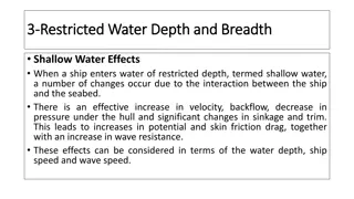
-
Resistance caused by shallow water effect
- Flow velocities under the hull increases in shallow water.
•
Increase of frictional resistance due to the velocities
•
P
ressure drop, suction, increase of wetted surface area
Increases frictional resistance
- The waves created in shallow water take more energy from
the ship than they do in deep water for the same speed.
Increases wave making resistance
O
t
h
e
r
T
y
p
e
o
f
R
e
s
i
s
t
a
n
c
e
s
Operating to Minimize
Resistance
Keep the hull clean
Operate at a prudent speed
–
Keep speed below “hump speed” to optimize
economy
So far we’ve discussed what resistance is and how it can
quantified using
:
-
R
T
by measuring the actual resistance force
-
C
T
dimensionless coefficients that can be used to compare
resistance between dissimilar hull shapes and sizes
We can now measure the resistance in a hull and use the data
to designing a ship’s power plant
-
Using the resistance data, an effective power plant can be designed
- Taking into account the relationship between
- Effective Horsepower,
EHP
- Shaft Horsepower,
SHP
7.7 Tow Tank Modeling
R
t
V
s
EHP
550
ft - lb
sec-HP
Resistance and power are related!
Resistance can be measured in two ways
:
-
Computer modeling
- Can be very difficult to mathematically model viscous flow in
3 dimensions
-
Tow Tank testing
- Producing a geometrically and dynamically similar model to test
- Relate model performance to expected actual ship performance
Tow Tank Modeling
Tow Tank testing is the obvious way to go! But to do so, your
“model” ship must meet some criteria:
…Note that a “minor” error in any length measurement will be
cubed (n
3
)in volume scaling!
Tow Tank Modeling
2.
Dynamic Similarity
-
Motion of the vessel must also be scaled, including:
- Ship’s velocity
- Acceleration
- Viscosity of the water
- Dynamic similarity can only be approximated as water’s viscosity
and the forces of gravity can not be manipulated
Tow Tank Modeling
The Law of Corresponding Speeds says:
Tow Tank Modeling
We’ve already defined
as:
If we wanted to solve for the scale speed for the model,
or
V
M
= V
S
-1/2
...NOTE! 1 kt is equal to 1.688 ft/sec! ALL velocities are done in feet/sec!
Tow Tank Modeling
Example 1
:
The USS Monitor was 197 ft long and 40 ft across the beam and was able to
maintain a maximum speed of 6 kts. You would like to create a model for
testing that is 5 ft long.
How wide should the model be? How fast should the model be towed to
represent the actual ship’s max speed?
= L
S
/L
M
= 197 ft /5 ft
= 39.4
Solving for the width,
= W
S
/W
M
W
M
= 40 ft/39.4
W
M
= 1.015 ft
Solving for the maximum speed,
V
M
= V
S
-1/2
V
M
= 6 kts (1.688 ft/sec-kts)
x
39.4
-1/2
V
M
= 10.128 ft/s
x
.1593
V
M
= 1.6134 ft/s
Example 2
:
The Yard Patrol (YP) is 110 ft long. It has a top speed of 13 kts on a good
day. It displaces 150 LT.
How long must a 1:25 scale model be? How fast must it be towed to
simulate the top speed?
= 25
(the scale is given!)
25 = L
S
/L
M
L
M
= 110ft/25
L
M
4.4 ft (52.8 in)
Solving for the maximum speed,
V
M
= V
S
-1/2
V
M
= 13 kts (1.688 ft/sec-kts)
x
25
-1/2
V
M
= 21.944 ft/s
x
.0.20
V
M
= 4.39 ft/s
Example Problem
You are the chief Naval Architect assigned to design
a new YP for the Naval Academy. You have
already decided on a displacement, hull size and
shape. You now need to use tow tank testing of a
model to determine the engine size and fuel
capacity required.
Ship Data:
–
=300LT Length=100ft Beam=25ft Draft=6ft
Wetted Surface Area=3225ft² Desired Max
Speed=15kts
Example Problem
•
The maximum length of model which the tow tank can
handle is 5ft. If the model is constructed of this length, to
maintain geometric similarity, what would be its beam?
•
Maintaining geometric similarity, what is the wetted
surface area of the model?
•
Maintaining geometric similarity, what is the displacement
of the model in pounds? (Assume tow tank is seawater.)
•
Maintaining dynamic similarity, at what speed in ft/s do
we need to tow the model?
•
At this speed, the model resistance is 6.58lb. Coefficient
of Viscous Resistance (model)(C
v
)=0.0064 What is the
wave making coefficient (C
w
)?
•
At 15kts, C
v
for the ship is 0.0030. What is the resistance
for the full size ship at this speed?
•
What is the EHP at this speed and, if we expect
p
=55%,
how many SHP are required?
Example Answer
•
Scale Factor =
=L
s
/L
m
=100ft/5ft=20;
B
m
=B
s
/
=25ft/20=1.25ft
•
A
m
=A
s
/
²=3225ft²/20²=8.06ft²
•
=F
B
=
gV Thus, it is proportional to submerged volume
which is proportional to
³;
m
=
s
/
³=300LT×(2240lb/LT)/20³=84lbs
•
Law of Corresponding Speeds:
v
m
=v
s
/
½
=15kts×(1.688ft/s-kt)/20
½
=5.7ft/s
•
C
T
=R
T
/(½
SV²)=6.58lb/[½×1.99lb-
s²/ft
4
×8.06ft²×(5.7ft/s)²]=0.0253; C
w
=C
T
-C
v
=0.0253-
0.0064=0.0189
•
C
ws
=C
wm
; C
T
=C
v
+C
w
=0.0189+0.0030=0.0219
•
R
T
=C
T
×½
SV²=0.0219×½×(1.99lb-
s²/ft
4
)×3225ft²×(15kt×1.688ft/s-kt)²=45,100lb
•
EHP=R
T
V/(550ft-lb/s-HP)=45,100lb×15kt×1.688ft/s-
kt/(550ft-lb/s-HP)=2076HP;
SHP=EHP/
p
=2076/0.55=3775HP
HUB
ROOT
BLADE TIP
TIP CIRCLE
ROTATION
LEADING
EDGE
TRAILING
EDGE
PRESSURE
FACE
SUCTION
BACK
7.8 Screw Propellers
PROPELLER
DISC
Definitions
•
Diameter(D)
: distance from tip to tip
•
Hub
: the connection between propeller and shaft
•
Blade Tip
: the furthest point on the blade
•
Blade Root
: the point where the blade meets the hub
•
Pitch(P)
:
Theoretical
distance a propeller would move in
one revolution
•
Pitch Angle
: Angle of the blade with respect to incoming flow.
It usually varies from root to tip.
•
Fixed Pitch
:
- The pitch is constant all the way from the blade root to
the blade tip.
- Blade is fixed to the hub and cannot be altered.
•
Tip Circle
: Circle described by the blade tip rotation
•
Propeller Disc
: The area circumscribed by the propeller’s tip circle
Screw Propellers
Hub
pitch
diameter
The distance that the blade travels in one revolution, P
- measured in feet
Propeller Pitch
Screw Propellers
Propeller Pitch Angle
The
pitch angle
relates the
pitch length
to the
circumference
of the propeller blade:
tan
= P
2
r
… Pitch angle
is the angle that any part of the blade makes perpendicular
with the water flow
Screw Propellers
Types of Propeller Pitch
1. Constant Pitch- The pitch angle does not change, it is the same at the
root as at the tip of the blade, but the pitch will vary or the pitch does
not change, but the pitch angle does change.
2.
Variable Pitch- The pitch angle changes as the distance from the root
changes (
is defined at a blade radius of .7r)
3.
Fixed Pitch- The blade is permanently attached to the hub and cannot
change.
4.
Controllable Pitch- The position of the blade can be altered while the
blade rotates, thereby changing the pitch angle.
Screw Propellers
Definitions
•
Pressure face :
- High pressure side of blade. The astern side when going ahead
•
Suction Back : Low pressure side. Surface opposite the face
•
Leading edge :
Forward edge of the blade, first to encounter the water stream
•
Trailing edge :
Last part of the blade to encounter the water stream
Screw Propellers
Screw Propellers
Propeller Action
Forward
Propeller Rotation
High Pressure Face
Suction Back
Relative Motion of Water Flow
Reaction Force
on Propeller
Propeller Thrust
Resistance to
Propeller Rotation
Pitch
Angle
Screw Propellers
Left hand screw
- Rotates Counter Clock-wise when viewed from astern
- Single screw ships use this type
Right hand screw
- Rotates Clock-wise when viewed from astern
Propeller Rotation
Counter Rotating Propellers
-
Have both a right and left hand screw
-
Eliminates torque created by the rotation
-
Torque will cause the stern to make a turn in
the direction of rotation
Screw Propellers
The Skewed Propeller
Highly Skewed Propeller for a DDG 51
Advantages
:
-
Reduced interaction between propeller
and rudder wake
- Reduced vibration and noise
Disadvantages
:
-
Expensive
-
Less efficient operating in reverse
Screw Propellers
Propeller Theory
•
S
p
e
e
d
o
f
A
d
v
a
n
c
e
•
The ship drags the surrounding water . This
wake
follows the
ship with a
wake speed
(
Vw
).
•
The flow speed at the propeller is,
Speed of Advance
Screw Propellers
Propeller Efficiency
(~70 % for well-designed PP.)
-
For a given T (Thrust),
Ao
(i.e.,
Diameter
) ;
C
T
;
Prop Eff.
The larger the diameter of propeller, the better the propeller efficiency
Maximum
Screw Propellers
Propeller Theory
Propellers generate thrust as soon as they
rotate, even before the ship starts moving
K
T
=T/(
n²D
4
)
–
K
T
=thrust coefficent
–
=water density
–
n=shaft RPM
–
D=propeller diameter
Screw Propellers
Propeller Cavitation
Cavitation occurs on propellers that are heavily loaded, or are experiencing a
high thrust loading coefficient
-
The formation and collapse of vapor bubbles on propeller blades where the
pressure has fallen below the vapor pressure of water
Screw Propellers
C
a
v
i
t
a
t
i
o
n
P
r
o
c
e
s
s
Pressure
(atm)
Vaporization Line
Temperature
(
°C)
LIQUID
VAPOR
20
100
1.0
P
v
A
B
C
Vapor pressure
15
°C 0.25 psi
100°C 14.7psi=1atm
=101 kPa
(‘A’ to ‘B’ – boiling water)
(‘A’ to ‘C’ – cavitation)
Screw Propellers
Screw Propellers
Blade Tip Cavitation
Sheet Cavitation
Navy Model Propeller 5236
Flow velocities at the tip are
fastest so that pressure drop
occurs at the tip first.
Large and stable region of
cavitation covering the suction
face of propeller.
Screw Propellers
Consequences of Cavitation
1) Low propeller efficiency (Thrust reduction)
2) Propeller erosion (Mechanical erosion)
(Severe damage to propeller : up to 180 ton/in
²
)
3) Vibration due to uneven loading
4) Cavitation
noise
due to impulsion by the bubble collapse
Screw Propellers
P
r
e
v
e
n
t
i
n
g
C
a
v
i
t
a
t
i
o
n
-
Remove fouling, nicks and scratch.
-
Increase or decrease the engine RPM smoothly to avoid
an abrupt change in thrust.
rapid change of rpm
high propeller thrust but small
change in V
A
larger C
T
cavitation &
low propeller efficiency
-
Keep appropriate pitch setting for controllable pitch propeller
-
For submarines, diving to deeper depths will delay or prevent
cavitation as hydrostatic pressure increases.
Screw Propellers
V
e
n
t
i
l
a
t
i
o
n
-
If a propeller operates too close to the water surface, surface
air or exhaust gases are drawn into the propeller blade due to
the localized low pressure around propeller.
-
The load on the propeller is reduced by the mixing of air or
exhaust gases into the water causing effects similar to those
for cavitation.
-
Ventilation often occurs in ships in a very light condition(small
draft) and in rough seas.
Screw Propellers
Example Problem:
Name the parts of a propellers:
•
__________________
•
___
•
_________
•
__________
•
__________
•
______________
•
____________
•
_____________
•
_____________
•
____________
Direction
of Rotation
Forward
R
Example Answer:
Name the parts of a propellers:
•
Propeller Radius (R)
•
Hub
•
Blade Tip
•
Blade Root
•
Tip Circle
•
Propeller Disc
•
Leading Edge
•
Trailing Edge
•
Pressure Face
•
Suction Back
Direction
of Rotation
Forward
R
Ship drive train and power systems play a crucial role in the propulsion of ships. Components like engines, reduction gears, screws, bearings, and seals work together to convert engine power into thrust horsepower (THP) that drives the propeller. Various types of horsepowers like effective horsepower (EHP), brake horsepower (BHP), shaft horsepower (SHP), delivered horsepower (DHP), and thrust horsepower (THP) are involved in the system. The relationship between these power magnitudes is important, with BHP being greater than SHP, DHP, THP, and EHP due to inevitable power losses from factors like heat, friction, and sound. Effective horsepower (EHP) is specifically related to the power required to move the ship hull at a given speed. Experimental methods like towing tank tests help determine EHP, which can be extrapolated to full-scale ships using Froude's Law.

Download Presentation

Please find below an Image/Link to download the presentation.
The content on the website is provided AS IS for your information and personal use only. It may not be sold, licensed, or shared on other websites without obtaining consent from the author.If you encounter any issues during the download, it is possible that the publisher has removed the file from their server.
You are allowed to download the files provided on this website for personal or commercial use, subject to the condition that they are used lawfully. All files are the property of their respective owners.
The content on the website is provided AS IS for your information and personal use only. It may not be sold, licensed, or shared on other websites without obtaining consent from the author.
E N D
Presentation Transcript
7.2 Ship Drive Train and Power Ship Drive Train System EHP Engine Reduction Gear Screw Strut Bearing Seals THP BHP SHP DHP
Ship Drive Train and Power EHP Engine Strut Reduction Gear Screw Bearing Seals THP DHP BHP SHP Brake Horsepower (BHP) - Power output at the shaft coming out of the engine before the reduction gears
Ship Drive Train and Power EHP Engine Strut Reduction Gear Screw Bearing Seals THP DHP BHP SHP Shaft Horsepower (SHP) - Power output at the shaft coming out of the reduction gears
Ship Drive Train and Power EHP Engine Strut Reduction Gear Screw Bearing Seals THP BHP DHP SHP Delivered Horsepower (DHP) - Power delivered to the propeller - DHP=SHP losses in shafting, shaft bearings and seals
Ship Drive Train and Power EHP Engine Strut Reduction Gear Screw Bearing Seals THP DHP BHP SHP Thrust Horsepower (THP) - Power created by the screw/propeller - THP=DHP Propeller losses - THP is the end result of all HP losses along the drive train
Ship Drive Train and Power EHP BHP SHP DHP THP Shaft Bearing Hull E/G R/G Prop. Relative Magnitudes BHP> SHP > DHP > THP > EHP The reverse relationship can NEVER be true because there is ALWAYS some loss of power due to heat, friction, and sound
7.3 Effective Horsepower (EHP) The power required to move the ship hull at a given speed in the absence of propeller action EHP is not related to Power Train System EHP can be determined from the towing tank experiments at the various speeds of the model ship EHP of the model ship is converted into EHP of the full scale ship by Froude s Law. Measured EHP V Towing carriage Towing Tank
Effective Horsepower (EHP) POWER CURVE YARD PATROL CRAFT Typical EHP Curve of YP 1000 Effective Horsepower, EHP (HP) 800 600 400 200 0 0 2 4 6 8 10 12 14 16 Ship Speed, Vs (Knots) The required EHP varies depending on the vessel s speed.
Effective Horsepower (EHP) EHP Calculation ft R (lb) V T S s = EHP(H ) = resistance hull total R P T ft lb S= 550 V speed of ship s H P ft lb ft J ( ) lb V = = = Power : R Watts T S s s s / 1 = 1 W 550 H atts P
7.4 Propulsion Efficiency The loss in HP along the drive train can be related in terms of EFFICIENCY, or Gear Efficiency gear = SHP BHP Shaft Horsepower Brake Horsepower -Highlights the loss of horsepower from the engine to the shaft as a result of the reduction gears - SHP is always less than BHP
Propulsion Efficiency Shaft Transmission Efficiency shaft = DHP SHP Delivered Horsepower Shaft Horsepower - The loss of horsepower from the reduction gears to the propeller due to the bearings and seals that support and seal the drive shaft - The loss of power is converted to heat and sound due to friction
Propulsion Efficiency Hull Efficiency (The loss of power will be a function of the hull design) EHP Effective Horsepower Thrust Horsepower H= THP - Hull efficiency changes due to hull-propeller interactions. - Well-designed ship : - Poorly-designed ship : H 1 H 1 Well-designed - Flow is not smooth. - THP is reduced. - High THP is needed to get designed speed. Poorly-designed
Propulsion Efficiency EHP Propeller Efficiency Screw THP propeller= DHP THP SHP DHP
Propulsion Efficiency Propulsive Efficiency (Coefficient (PC)) P = EHP SHP Effective Horsepower Shaft Horsepower - Combines the losses due to the bearings, guides, and the propeller efficiency -Compares the output from the reduction gears to the required towing HP -Commonly ranges from 55 - 75% -Once p is found, can try different power plants, gearing, and fuel efficiencies
Example: Through modeling of a ship s design, it is found that the towing horsepower required to maintain a speed of 20 knots is 23,500 HP. Assuming a propulsive efficiency of 68%, what is the expected required power output from the reduction gears (shaft horsepower)? Solution: P = EHP SHP .68 = 23,500 HP SHP SHP = 23,500 HP / .68 SHP = 34,559 HP
Example Problem What are the various components, HPs, s and common values for s for the drawing below? _HP _HP _HP _HP _HP gear=_HP/_HP (~__-__%) shaft=_HP/_HP (~__-__%) prop=_HP/_HP (~__-__%) H=_HP/_HP P=PC=_HP/_HP (~__-__%)
Example Answer What are the various components, HPs, s and common values for s for the drawing below? BHP SHP DHP EHP THP Prime Mover Reduction Gear Shafting & Bearings Propeller Hull gear=SHP/BHP (~98-99%) shaft=DHP/SHP (~97-98%) prop=THP/DHP (~70-75%) H=EHP/THP P=PC=EHP/SHP (~55-75%)
7.5 Total Hull Resistance Total Hull Resistance (RT) The force that the ship experiences opposite to the motion of the ship as it moves. EHP Calculation ft R (lb) V = total hull resistance R T S s T = EHP(H ) S= V speed of ship P ft lb 550 s H P
Total Hull Resistance Coefficient of Total Hull Resistance - Non-dimensional value of total resistance R lb = C T non - dimension 2 T 2S 5 . 0 V 2 lb s ft 2 ft s 4 ft s = Coefficien t of resistance hull total calm in water C T resistance hull Total = R T = Fluid = density Speed of ship V S = submerged the on area surface wetted hull S
Total Hull Resistance Coefficient of Total Hull Resistance -Total Resistance of full scale ship can be determined using V S C , , and T S 2 = ( ) 5 . 0 R lb SV C T S T determined model the by test : C T available : S from water property table obtained : from Curves of form : Full scale ship speed V S
Total Hull Resistance Relation of Total Resistance Coefficient and Speed TOTAL RESISTANCE CURVE YARD PATROL CRAFT 20000 Total Resistance, Rt (lb) 15000 10000 5000 0 0 2 4 6 8 10 12 14 16 Ship Speed, Vs (knots) 2 2 R C V EHP R V C V V T T S T S T S S n n n n V V S S from = = 2 at low speed from 3 at low speed t high at 5 o speed high at 6 to speed
7.6 Total Hull Resistance Resistance values, denoted by R, are dimensional values RT = Total hull resistance is the sum of all resistance RT = RAA + RW + RV Air Resistance Wave Making Resistance Viscous Resistance RAA = Resistance caused by calm air on the superstructure RW = Resistance due to waves caused by the ship - A function of beam to length ratio, displacement, hull shape & Froude number (ship length & speed) RV = Viscous resistance (frictional resistance of water) - A function of viscosity of water, speed, and wetted surface area of ship For pilots, this is subsonic, incompressible drag
Total Hull Resistance Total Resistance and Relative Magnitude of Components Air Resistance Hollow Wave-making Hump Viscous Speed (kts) - Low speed : Viscous R - Higher speed : Wave-making R - Hump (Hollow) : location is function of ship length and speed.
Components of Total Resistance Viscous Resistance - Resistance due to the viscous stresses that the fluid exerts on the hull. ( due to friction of the water against the surface of the ship) - Viscosity, ship s velocity, wetted surface area of ship generally affect the viscous resistance. Wave-Making Resistance - Resistance caused by waves generated by the motion of the ship - Wave-making resistance is affected by beam to length ratio, displacement, shape of hull, Froude number (ship length & speed) Air Resistance - Resistance caused by the flow of air over the ship with no wind present - Air resistance is affected by projected area, shape of the ship above the water line, wind velocity and direction - Typically 4 ~ 8 % of the total resistance
Components of Total Resistance Dimensionless Coefficients CT = Coefficient of total hull resistance CT = CV + CW CV = Coefficient of viscous resistance over the wetted area of the ship as it moves through the water - CF = Tangential component (skin resistance) - KCF = Normal component (viscous pressure drag) CW = Coefficient of wave-making resistance
Coefficient of Viscous Resistance (CV) Viscous Flow around a ship Real ship : Turbulent flow exists near the bow. Model ship : Studs or sand strips are attached at the bow to create the turbulent flow.
Coefficient of Viscous Resistance (CV) Coefficients of Viscous Resistance - Non-dimensional quantity of viscous resistance - It consists of tangential and normal components. CF=tangential (skin friction) component of viscous resistance KCF=normal (viscous pressure/form drag) component of viscous friction + = tangential V C C C = C + KC normal F F flow ship stern bow Tangential Component : CF - Tangential stress is parallel to ship s hull and causes a net force opposing the motion ; Skin Friction - It is assumed can be obtained from the experimental data of flat plate. C F
Coefficient of Viscous Resistance (CV) = Tangential Component of C C V F . 0 075 = C Semi-empirical equation F 2 (log ) 2 R 10 n LV = R S n = Reynolds Number R n = L = (ft) L pp Speed(ft/s Ship ) V S = 2 Kinematic Viscosity (ft /s) = 5 - 2 1.2260 10 ft /s for fresh water = 5 - 2 1.2791 10 ft /s for salt water
Coefficient of Viscous Resistance (CV) Boundary Layer Separation Resistance Bernoulli s Equation: p/ +V /2+gz=constant Viscous Pressure/Form Drag Laminar Flow High Velocity/ Low Pressure Low Velocity/ High Pressure Low Velocity/ High Pressure Turbulent Flow Boundary Layer High Velocity/ Low Pressure Boundary Layer Separation Boundary Layer Low Velocity/ High Pressure Turbulent Wake
Coefficient of Viscous Resistance (CV) Tangential Component: CF - Relation between viscous flow and Reynolds number Laminar flow : In laminar flow, the fluid flows in layers in an orderly fashion. The layers do not mix transversely but slide over one another. Turbulent flow : In turbulent flow, the flow is chaotic and mixed transversely. Flow over flat plate Laminar Flow Turbulent Flow about Rn 5 5 10 about 5 5 Rn 10
Coefficient of Viscous Resistance (CV) Normal Component: KCF - Normal component causes a pressure distribution along the underwater hull form of ship - A high pressure is formed in the forward direction opposing the motion and a lower pressure is formed aft. - Normal component generates the eddy behind the hull. - It is affected by hull shape. Fuller shape ship has larger normal component than slender ship. large eddy Full ship Slender ship small eddy
Coefficient of Viscous Resistance (CV) Normal Component: KCF - It is calculated by the product of Skin Friction with Form Factor. = Normal Component of C K C v F = Skin Friction Coeff. C F = Form Factor K 2 B 3 (ft ) ( ) B ft 19 = K ( ) ( ) ( ) ( ) L ft ft T ft L ft
Coefficient of Viscous Resistance (CV) = + = C + K C C tangential C . 0 C F F V normal 075 R 2 B 3 (ft ) ( ) B ft = C 19 = K F 2 (log ) 2 ( ) ( ) ( ) ( ) L ft ft T ft L ft 10 n LV = K= Form Factor R S n = Reynolds Number R n = L = (ft) L pp Speed(ft/s Ship ) V S = 2 Kinematic = Viscosity (ft /s) 5 - 2 1.2260 10 ft /s for fresh water = 5 - 2 1.2791 10 ft /s for salt water
Coefficient of Viscous Resistance (CV) Reducing the Viscous Resistance Coeff. - Method : Increase L while keeping the submerged volume constant 1) Form Factor K Normal component KCF Slender hull is favorable. ( Slender hull form will create a smaller pressure difference between bow and stern.) 2) Reynolds No. Rn CF KCF
Froude Number Fn The Froude Number (inertia force/gravity force) is another dimensionless value derived from model testing: Fn = V \/gL Also used, but not dimensionless, is the Speed-to-Length Ratio: Speed-to-Length Ratio = V \/L ...Velocity is typically expressed in Knots (1 knot = 1.688ft/s)
Coefficient of Wave Resistance CW Typical Wave Patterns are made up of TRANSVERSE and DIVERGENT waves Stern divergent wave Bow divergent wave Bow divergent wave L Transverse wave Wave Length
Coefficient of Wave Resistance CW Transverse wave System It travels at approximately the same speed as the ship. At slow speed, several crests exist along the ship length because the wave lengths are smaller than the ship length. As the ship speeds up, the length of the transverse wave increases. When the transverse wave length approaches the ship length, the wave making resistance increases very rapidly. This is the main reason for the dramatic increase in Total Resistance as speed increases.
Coefficient of Wave Resistance CW Transverse wave System Vs < Hull Speed Slow Speed Wave Length Vs Hull Speed High Speed Wave Length Hull Speed : speed at which the transverse wave length equals the ship length. (Wavemaking resistance drastically increases above hull speed)
Coefficient of Wave Resistance CW Divergent Wave System It consists of Bow and Stern Waves. Interaction of the bow and stern waves create the Hollow or Hump on the resistance curve. Hump : When the bow and stern waves are in phase, the crests are added up so that larger divergent wave systems are generated. Hollow : When the bow and stern waves are out of phase, the crests matches the trough so that smaller divergent wave systems are generated.
Coefficient of Wave Resistance CW Air Resistance Hollow Wave-making Hump Viscous Speed (kts) - Low speed : Viscous R - Higher speed : Wave-making R - Hump (Hollow) : location is function of ship length and speed.
Coefficient of Wave Resistance CW Calculation of Wave-Making Resistance Coeff. Wave-making resistance is affected by - beam to length ratio - displacement - hull shape - Froude number The calculation of the coefficient is far difficult and inaccurate from any theoretical or empirical equation. (Because mathematical modeling of the flow around ship is very complex since there exists fluid-air boundary, wave-body interaction) Therefore model test in the towing tank and Froude expansion are needed to calculate the Cw of the real ship.
Coefficient of Wave Resistance CW It takes energy to produce waves, and as speed increases, the energy required is a square function of velocity! Lwave = 2 V2 g The limiting speed, or hull speed, can be found as: V = 1.34\/Ls Note: Remember at the hull speed, Lwave and Ls are approximately equal!
Coefficient of Wave Resistance CW Reducing Wave Making Resistance 1) Increasing ship length to reduce the transverse wave - Hull speed will increase. - Therefore increment of wave-making resistance of longer ship will be small until the ship reaches to the hull speed. - EX : FFG7 : ship length 408 ft hull speed 27 KTS CVN65 : ship length 1040 ft hull speed 43 KTS
Coefficient of Wave Resistance CW Reducing Wave Making Resistance 2) Attaching Bulbous Bow to reduce the bow divergent wave - Bulbous bow generates the second bow waves . - Then the waves interact with the bow wave resulting in ideally no waves, practically smaller bow divergent waves. - EX : DDG 51 : 7 % reduction in fuel consumption at cruise speed 3% reduction at max speed. design &retrofit cost : less than $30 million life cycle fuel cost saving for all the ship : $250 mil. Tankers & Containers : adopting the Bulbous bow
Coefficient of Wave Resistance CW Bulbous Bow
Coefficient of Total Resistance Coefficient of total hull resistance = + + C C = C C + T V W + A + 1 C ( K) C C F W A Correlatio : A Allowance n C Correlation Allowance It accounts for hull resistance due to surface roughness, paint roughness, corrosion, and fouling of the hull surface. It is only used when a full-scale ship prediction of EHP is made from model test results. For model, For ship, empirical formulas can be used. = Since model surface smooth is 0 . C A
Other Type of Resistances Appendage Resistance - Frictional resistance caused by the underwater appendages such as rudder, propeller shaft, bilge keels and struts - 2 24% of the total resistance in naval ship. Steering Resistance - Resistance caused by the rudder motion. - Small in warships but troublesome in sail boats Added Resistance - Resistance due to sea waves which will cause the ship motions (pitching, rolling, heaving, yawing).
Other Type of Resistances Increased Resistance in Shallow Water - Resistance caused by shallow water effect - Flow velocities under the hull increases in shallow water. Increase of frictional resistance due to the velocities Pressure drop, suction, increase of wetted surface area Increases frictional resistance - The waves created in shallow water take more energy from the ship than they do in deep water for the same speed. Increases wave making resistance
Operating to Minimize Resistance Keep the hull clean Operate at a prudent speed Keep speed below hump speed to optimize economy


")
")
")


")
")
")
")
")
")
")
")
")