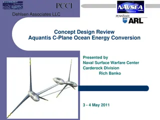
Scaled Blade Design and Rotor Progress Updates
This series of images showcases the stress analysis, extreme loads testing, loft and tooling progress, and hub design updates for a scaled blade design project. The stress analysis includes considerations for torque, thrust, and safety factors, with images detailing the results and adjustments made. Loft and tooling progress images highlight advancements in manufacturing ease and alignment, while the hub design progress focuses on accommodating necessary components. All information is labeled as company confidential and proprietary.

Download Presentation

Please find below an Image/Link to download the presentation.
The content on the website is provided AS IS for your information and personal use only. It may not be sold, licensed, or shared on other websites without obtaining consent from the author.If you encounter any issues during the download, it is possible that the publisher has removed the file from their server.
You are allowed to download the files provided on this website for personal or commercial use, subject to the condition that they are used lawfully. All files are the property of their respective owners.
The content on the website is provided AS IS for your information and personal use only. It may not be sold, licensed, or shared on other websites without obtaining consent from the author.
E N D
Presentation Transcript
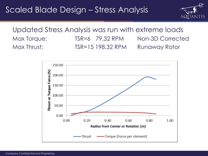
Scaled Blade Design Stress Analysis Updated Stress Analysis was run with extreme loads Max Torque: TSR=6 79.32 RPM Max Thrust: TSR=15 198.32 RPM Non-3D Corrected Runaway Rotor Company Confidential and Proprietary
Scaled Blade Design Stress Analysis Extreme Loads considered are conservative ~ 78% reduction due to test case adjustments Red: Above max torque or below 0 torque Green: Above design TSR Yellow: Max Thrust within constraints Nominal speed and TSR testing (1.6m/s, TSR=8) possible for froude scale up to 1/8.2 (250kW nameplate) High speed testing at nominal TSR (2.2m/s, TSR=8) possible for froude scale up to 1/11 (500kW nameplate) Runaway rotor testing (TSR=15) possible at nominal speed (1.6m/s) for froude scale up to 1/19.2 (1500kW nameplate) Company Confidential and Proprietary
Scaled Blade Design Stress Analysis Updated Stress Analysis was run with extreme loads Spud constrained on four sides Company Confidential and Proprietary
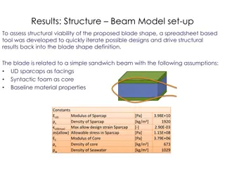
Scaled Blade Design Stress Analysis Carbon Compression Molded Blade Results Stress Factor of Safety 1.15 Max Deflection: 86mm Company Confidential and Proprietary
Scaled Blade Design Loft and Tooling Progress Loft root design was updated to ease manufacturing Scale SLA tooling was successfully trialed at NSWC Root Spud was aligned with innermost section Company Confidential and Proprietary
Scaled Rotor Design Hub Progress The Hub design has been updated to accommodate Spud SLA Inserts Aluminum Hub Company Confidential and Proprietary