RF Circuit Design and Impedance Matching Techniques
Learn about impedance matching, power transfer, resonant circuits, and the application of square waves in RF circuit design. Explore the modeling of coaxial cables and prepare for lab studies on cables and devices under test.

Download Presentation

Please find below an Image/Link to download the presentation.
The content on the website is provided AS IS for your information and personal use only. It may not be sold, licensed, or shared on other websites without obtaining consent from the author. If you encounter any issues during the download, it is possible that the publisher has removed the file from their server.
You are allowed to download the files provided on this website for personal or commercial use, subject to the condition that they are used lawfully. All files are the property of their respective owners.
The content on the website is provided AS IS for your information and personal use only. It may not be sold, licensed, or shared on other websites without obtaining consent from the author.
E N D
Presentation Transcript
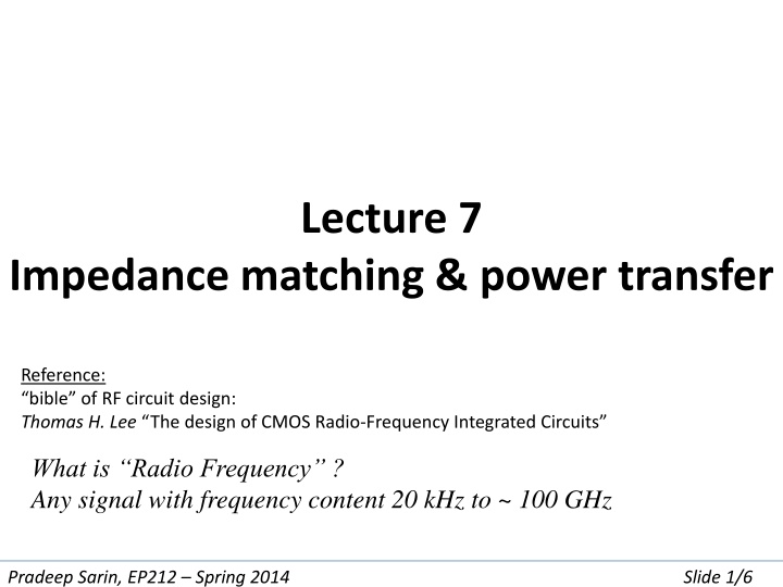
Lecture 7 Impedance matching & power transfer Reference: bible of RF circuit design: Thomas H. Lee The design of CMOS Radio-Frequency Integrated Circuits What is Radio Frequency ? Any signal with frequency content 20 kHz to ~ 100 GHz Pradeep Sarin, EP212 Spring 2014 Slide 1/6
Consider what happens when we introduce L and C into a circuit Series L 1 R = + + V I R jwL V C jwC I Parallel V 1 1 = + + I V jwC I R L C R jwL Pradeep Sarin, EP212 Spring 2014 Slide 2/6
The resonant circuit picks out a frequency Series L Vout 1 R Vin = + + V I R jwL V C jwC I Can show: V L = out ( 1 ) ( ) V 2 2 + 2 2 L R LC in For 0= 1/ LC: Vout/Vin = 1 else < 1 Pradeep Sarin, EP212 Spring 2014 Slide 3/6
A square wave is really a sum of sines (from Fourier analysis) When the square wave is applied as Vin Frequencies near 0 will pass through, others will be attenuated L Vout R Vin C Pradeep Sarin, EP212 Spring 2014 Slide 4/6
A coaxial cable is modelled as a series LC network See http://goo.gl/l3p7s7 for a detailed analysis of a how a cable works Pradeep Sarin, EP212 Spring 2014 Slide 5/6
Preparation for Lab 7 Study Cables Source ZS (VS) Cable Z0 (DUT) Cable Z0 (DUT) Load ZL Device Under Test Pradeep Sarin, EP212 Spring 2014 Slide 6/6