Proper Control of Cavity Voltage for Acceleration
Explore the crucial aspects of controlling cavity accelerating voltage in particle accelerators. Topics include operational limits, gradient performance, feedback control, and more. Understanding these concepts ensures stable and efficient linac operation.

Download Presentation

Please find below an Image/Link to download the presentation.
The content on the website is provided AS IS for your information and personal use only. It may not be sold, licensed, or shared on other websites without obtaining consent from the author. If you encounter any issues during the download, it is possible that the publisher has removed the file from their server.
You are allowed to download the files provided on this website for personal or commercial use, subject to the condition that they are used lawfully. All files are the property of their respective owners.
The content on the website is provided AS IS for your information and personal use only. It may not be sold, licensed, or shared on other websites without obtaining consent from the author.
E N D
Presentation Transcript
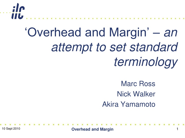
Overhead and Margin an attempt to set standard terminology Marc Ross Nick Walker Akira Yamamoto 1 10 Sept 2010 Overhead and Margin
Highest Gradient Operation Gradient Quench Gradient Feed-back Limit ( LLRF ) Operating Gradient V-Sum Feed-back Margin 1 ~ 2 MV Lorentz Detuning Compensation Error QL = 3x10⁶, f = 50 Hz, = 13 QL = 2.0x10⁶, f = 50 Hz, = 8.7 V = - 5 % V = - 2.3 % Time 10 Sept 2010 Overhead and Margin 2
Cavity Characteristics From its first cold power-on test through to its operation with beam we should track: gradient performance and field emission (also Q_0). Gradient limit(s) and perceived origin of the limit (precision to be discussed and defined) 3 10 Sept 2010
Gradient Performance (Field emission is similar) In vertical dewar low power CW test, a maximum gradient (and an associated Q_0) is observed and recorded: vertical test observed gradient limit , And observed Q_0 at the limit. in subsequent testing: horizontal test observed gradient limit and cryomodule test observed gradient limit (Noguchi: Quench Gradient ) are recorded in general, are each different . 4 10 Sept 2010
Operation in operation, (administratively controlled): operational gradient limit beyond which the cavity should not be routinely operated. (Noguchi: Feedback Limit ) Furthermore: power-limited gradient beyond which the capabilities of the RF power source (and power distribution system) are exceeded. Others: limitations due to cryogenics, controls, coupler, and etc) This defines the maximum capability of the linac - but not how it is stably operated: CONTROLS 5 10 Sept 2010
Controls ( Feedback and Control Margin ) Proper control of the cavity accelerating voltage includes control of: 1) the RF power source, 2) the power distribution system and coupler, 3) the cavity frequency resonance, and 4) beam current. In general, closed loop feedback (or trim) with adequate control actuator range, setting precision and bandwidth is required for each. To know the effectiveness of the voltage control, the performance of each should be examined. 6 10 Sept 2010
Selected terms (1): Observed Gradient limit The observed limit for steady superconducting operation in Vertical Low Power test, Horizontal test, cryomodule test and linac operation Cavity should not be operated beyond this limiting voltage after installation in the linac; the limit may depend on duration/time The difference between the vertical test Observed Gradient limit and the cryomodule test Observed Gradient limit. Beam current and input power match no reflected power Change in cavity voltage between the first bunch and the last bunch- typ P/P Operational Gradient limit Cryomodule assembly Gradient limit change Matched Condition Gradient slope 7 10 Sept 2010
Selected Terms (2): Lorentz Force Detuning Cavity resonant frequency shift due to 1.3 GHz RF energy pressure intentional cavity tuning offset used to achieve partial LFD compensation and minimize LFD compensation mover stroke amplitude Distribution characteristics for a sequence of machine pulses; bunch intensity, average beam current, HLRF modulator pulse, etc RMS vs P/P Pre-detuning Pulse to pulse fluctuation/pulse to pulse stability Within the pulse fluctuation 8 10 Sept 2010
Selected Terms (3): Loaded Q Q_l External Q P_k Pulse to pulse fluctuation/pulse to pulse stability (Loaded Quality factor) (External Quality factor) Input forward power Distribution characteristics for a sequence of machine pulses; bunch intensity, average beam current, HLRF modulator pulse, etc Within the pulse fluctuation 9 10 Sept 2010
Others: Tuning Overhead Energy overhead Microphonics Residual vibration Vector Sum Slow tuner Fast tuner Cavity Grouping Gradient spread Klystron saturation 10 10 Sept 2010
Our task: Develop an optimized cost-conscious ILC linac design We know too little about optimizing high gradient, 9 mA, CM performance To Note: P_k/Q_l (Michizono) RDR DESIGN INCLUDES P_k/Q_l remote control via 3 stub tuner motors (and Q_l control via coupler) 11 10 Sept 2010
Detuning , Ql tolerance 304 302 300 Power [kW] 298 +/-15% 296 0.6% 294 2% additional power 292 290 2.5 2.7 2.9 3.1 3.3 3.5 3.7 3.9 4.1 4.3 4.5 50 Hz Ql [x1e6] 50 Hz detuning requires additional 2% rf power +/-15% Ql difference requires 0.6% additional power. BAW1 (Sep.,2010) 12
Summary Shin Michizono RDR DRFS (PkQl) DRFS(Cavity grouping) Operation gradient Max. 33 MV/m Average 31.5 MV/m Max. 38 MV/m RF source 10 MW 800 kW Waveguide loss 8% power 2% power 2% power Static loss (Ql, Pk) 2% power 2% power 2% power Kly Hv ripple 2.5% power 2.5% power 2.5% power Microphonics 2% power 2% power 2% power Reflection 0% power 14% power 0% power Other LLRF margin 10% power 10% power 5%~10% power Ql tolerance 3% (2) 3% (2) Pk tolerance 0.2dB (2) 0.2dB (2) Detuning tolerance 15Hz rms(3) 20Hz rms (3) Beam current offset 2% rms (3) (1) LLRF overhead ~5% (2) Cavity gradient tilt (repetitive) ~5% (3) Pulse-to-pulse gradient fluctuation ~1%rms We have to examine these numbers experimentally. Tolerance should be discussed with cavity and HLRF group. If the tolerance is smaller, better gradient tilt would be possible. 10-9-9, A. Yamamoto 13 BAW1-2, Technical Address
14 10 Sept 2010
15 10 Sept 2010
LFD Compensation (Noguchi: DLD compensation) Warren Schappert and Yuriy Pischalnikov Piezo control using Least-Square minimization Of Finite Impulse Response Calibration Matrix 16 10 Sept 2010
Schappert Pischalnikov Fermilab TD Detuning Response to Piezo pulse time 17 10 Sept 2010


:")
:")
:")