Processor Hazards and Pipeline Stalls
Explore processor hazards like load-use and data hazards, along with strategies to avoid stalls in the pipeline. Discover how to detect and handle hazards efficiently for optimal performance in computer architecture. Learn about forwarding conditions, datapath design, and the impact of hazards on instruction execution.

Download Presentation

Please find below an Image/Link to download the presentation.
The content on the website is provided AS IS for your information and personal use only. It may not be sold, licensed, or shared on other websites without obtaining consent from the author.If you encounter any issues during the download, it is possible that the publisher has removed the file from their server.
You are allowed to download the files provided on this website for personal or commercial use, subject to the condition that they are used lawfully. All files are the property of their respective owners.
The content on the website is provided AS IS for your information and personal use only. It may not be sold, licensed, or shared on other websites without obtaining consent from the author.
E N D
Presentation Transcript
Chapter 4 The Processor 1
Revised Forwarding Condition MEM hazard if (MEM/WB.RegWrite and (MEM/WB.RegisterRd 31) and not(EX/MEM.RegWrite and (EX/MEM.RegisterRd 31) and (EX/MEM.RegisterRd ID/EX.RegisterRn1)) and (MEM/WB.RegisterRd = ID/EX.RegisterRn1)) ForwardA = 01 if (MEM/WB.RegWrite and (MEM/WB.RegisterRd 31) and not(EX/MEM.RegWrite and (EX/MEM.RegisterRd 31) and (EX/MEM.RegisterRd ID/EX.RegisterRm2)) and (MEM/WB.RegisterRd = ID/EX.RegisterRm2)) ForwardB = 01 2
Datapath with Forwarding The signed-immediate input to the ALU, needed by loads and stores, is missing from the datapath 3
Datapath with Forwarding Multiplexor chooses between the ForwardB multiplexor output and the signed immediate 4
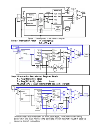
Load-Use Hazard Detection Checking for Load instruction is decoded in ID stage ALU operand register numbers in ID stage are given by IF/ID.RegisterRn1, IF/ID.RegisterRm2 Load-use hazard IF (ID/EX.MemRead and ((ID/EX.RegisterRd = IF/ID.RegisterRn1) or (ID/EX.RegisterRd = IF/ID.RegisterRm1))) stall the pipeline If the instruction in the ID stage is stalled, then the instruction in the IF stage must also be stalled; otherwise, we would lose the fetched instruction. prevent the PC register and the IF/ID pipeline register from changing. 5
How to Stall the Pipeline Deasserting all eight control signals (setting them to 0) in the EX, MEM, and WB stages will create a do nothing or nop instruction. By identifying the hazard in the ID stage, we can insert a bubble into the pipeline by changing the EX, MEM, and WB control fields of the ID/EX pipeline register to 0. Prevent update of PC and IF/ID register Using instruction is decoded again Following instruction is fetched again 1-cycle stall allows MEM to read data for LDUI Can subsequently forward to EX stage 6
Load-Use Data Hazard Stall inserted here 7
Stalls and Performance The BIG Picture The BIG Picture Stalls reduce performance But are required to get correct results Compiler can arrange code to avoid hazards and stalls Requires knowledge of the pipeline structure 9
4.8 Control Hazards Branch Hazards If branch outcome determined in MEM, predict branch not taken Flush these instructions (Set control values to 0) PC 10
Reducing Branch Delay Move the conditional branch execution earlier in the pipeline, then fewer instructions need be flushed. It requires two actions to occur earlier: computing the branch target address and evaluating the branch decision Move hardware from EX stage to determine outcome to ID stage Target address adder Register comparator to see if it is zero This will require additional forwarding and hazard detection hardware we will need to forward results to the zero test logic that operates during ID. To flush instructions in the IF stage, add a control line, called IF.Flush, that zeros the instruction field of the IF/ID pipeline register. Clearing the register transforms the fetched instruction into a nop. 11
Reducing Branch Delay Example: branch taken, assuming the pipeline is optimized for branches that are not taken, and that we moved the branch execution to the ID stage: 36: SUB X10, X4, X8 40: CBZ X1, X3, 8 // PC-relative branch to 40+8*4=72 44: AND X12, X2, X5 48: ORR X13, X2, X6 52: ADD X14, X4, X2 56: SUB X15, X6, X7 ... 72: LDUR X4, [X7,#50] 12
Dynamic Branch Prediction In deeper and superscalar pipelines, branch penalty is more significant Use dynamic prediction Branch prediction buffer (aka branch history table) Indexed by recent branch instruction addresses Stores outcome (taken/not taken) To execute a branch Check table, expect the same outcome Start fetching from fall-through or target If wrong, flush pipeline and flip prediction 15
1-Bit Predictor: Shortcoming Inner loop branches mispredicted twice! outer: inner: CBZ , , inner CBZ , , outer Mispredict as taken on last iteration of inner loop Then mispredict as not taken on first iteration of inner loop next time around 16
2-Bit Predictor Only change prediction on two successive mispredictions 17
Calculating the Branch Target Even with predictor, still need to calculate the target address 1-cycle penalty for a taken branch Branch target buffer Cache of target addresses (destination PC) or destination instruction Indexed by PC when instruction fetched If hit and instruction is branch predicted taken, can fetch target immediately Correlating predictor A branch predictor that combines local behavior of a particular branch and global information about the behavior of some recent number of executed branches. Tournament branch predictor A branch predictor with multiple predictions for each branch and a selection mechanism that chooses which predictor to enable for a given branch. 18
4.9 Exceptions Exceptions and Interrupts Control is the most challenging aspect of processor design: it is both the hardest part to get right and the toughest part to make fast. One of the demanding tasks of control is implementing exceptions and interrupts Unexpected events requiring change in flow of control Different ISAs use the terms differently Exception Arises within the CPU e.g., undefined opcode, overflow, syscall, Interrupt From an external I/O controller Detecting exception conditions and taking the appropriate action is often on the critical timing path of a processor, which determines the clock cycle time and thus performance. Dealing with them without sacrificing performance is hard 19
Handling Exceptions Save PC of offending (or interrupted) instruction In LEGv8: Exception Link Register (ELR) Transfer control to the operating system at some specified address For the operating system to handle the exception, it must know the reason for the exception Communicate the reason for an exception through a register In LEGv8: Exception Syndrome Register (ESR) We ll assume 1-bit 0 for undefined opcode, 1 for overflow 20
An Alternate Mechanism Vectored Interrupts Handler address determined by the cause Exception vector address to be added to a vector table base register: Unknown Reason: Floating-point arithmetic exception: System Error (hardware malfunction): Instructions either Deal with the interrupt, or Jump to real handler 00 0000two 10 1100two 11 1111two 21
Handler Actions Read cause, and transfer to relevant handler Determine action required If restartable Take corrective action use ELR to return to program Otherwise Terminate program Report error using ESR, cause, 22
Exception Handling in LEGv8 Exception not vectored (as in LEGv8) A single interrupt entry point for all exceptions - 0000 0000 1C09 0000 operating system decodes the status register to find the cause Two additional registers to our current LEGv8 implementation: ELR: A 64-bit register used to hold the address of the affected instruction. ESR: A register used to record the cause of the exception. In the LEGv8 architecture, this register is 32 bits, although some bits are currently unused. 23
Exceptions in a Pipeline Exceptions in a pipelined implementation - another form of control hazard Consider hardware malfunction on add in EX stage ADD X1, X2, X1 Flush add and subsequent instructions Prevent X1 from being clobbered as Destination register EX.Flush signal to prevent the instruction in the EX stage from writing its result in the WB stage. Many exceptions require that we complete previous instructions flush the instruction and restart it from the beginning after the exception is handled. Set ESR and ELR register values Transfer control to handler Similar to mispredicted branch Use much of the same hardware 24
Pipeline with Exceptions LEGv8 exception address 0000 0000 1C09 0000 25
Exception Properties Restartable exceptions Pipeline can flush the instruction Handler executes, then returns to the instruction Refetched and executed from scratch PC saved in ELR register Identifies causing instruction Actually PC + 4 is saved Handler must adjust 26
Exception Example Exception on ADD in 40 44 48 4C 50 54 assume the instructions to be invoked on an exception begin like this: 80000180 STUR X26, [X0,#1000] 80000184 STUR X27, [X0,#1008] SUB X11, X2, X4 AND X12, X2, X5 ORR X13, X2, X6 ADD X1, X2, X1 SUB X15, X6, X7 LDUR X16, [X7,#100] 27
Multiple Exceptions Pipelining overlaps multiple instructions Could have multiple exceptions at once Simple approach: deal with exception from earliest instruction Flush subsequent instructions Precise exceptions - always associating the proper exception with the correct instruction Imprecise exceptions - Interrupts or exceptions in pipelined computers that are not associated with the exact instruction that was the cause of the interrupt or exception. In complex pipelines Multiple instructions issued per cycle Out-of-order completion Maintaining precise exceptions is difficult! 30