Pipeline Hazards in Computer Architecture
 undefined


Pipeline
Hazards
There
are
situations,
called
hazards,
that
prevent
the
next
instruction
in
the
instruction
stream
from
executing
during
its
designated
cycle
There
are
three
classes
of
hazards
Structural
hazard
Data
hazard
Branch
hazard
Structural Hazards
.
They arise
from
resource
conflicts when
the
hardware cannot
support
all
possible combinations
of
instructions in simultaneous overlapped
execution.
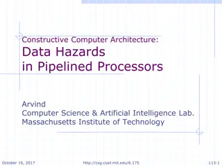
Data Hazards
.
They arise when an
instruction depends
on
the
result
of a
previous
instruction
in
a
way
that is
exposed
by
the
overlapping of
instructions in the
pipeline.
Control Hazards
.
They
arise from
the
pipelining
of
branches
and
other
instructions
that
change
the
PC.
What
Makes
Pipelining
Hard?
P
o
w
e
r
f
a
i
l
i
n
g
,
A
r
i
t
h
m
e
t
i
c
o
v
e
r
f
l
o
w
,
I
/
O
d
e
v
i
c
e
r
e
q
u
e
s
t
,
O
S
c
a
l
l
,
P
a
g
e
f
a
u
l
t
Pipeline
Hazards
S
t
r
u
c
t
u
r
a
l
h
a
z
a
r
d
Resource conflicts
when
the
hardware
cannot
support
all
possible
combination
of
instructions
simultaneously
D
a
t
a
h
a
z
a
r
d
An
instruction
depends
on
the
results
of
a
previous
instruction
B
r
a
n
c
h
h
a
z
a
r
d
Instructions
that
change
the
PC
Structural
hazard
Some
pipeline processors have
shared
a
single-
memory
pipeline
for
data
and
instructions
M
Single
Memory
is
a
Structural
Hazard
Load
Instr
1
Instr
2
Instr
3
Instr
4
A
L
U
M
Reg
M
Reg
A
L
U
M
Reg
M
Reg
A
L
U
M
Reg
M
Reg
A
L
U
Reg
M
Reg
A
L
U
M
Reg
M
Reg
•
r
C
a
n
’
t
r
e
a
d
s
a
m
e
m
e
m
o
r
y
t
w
i
c
e
i
n
s
a
m
e
c
l
o
c
k
c
y
c
l
e
I
n
s
t
r
.
O
r
d
e
Time (clock
cycles)
Structural
hazard
Fetch
I
n
s
t
r
u
c
t
i
on
(FI)
Fetch
Operand
(FO)
Decode
In
s
t
ruct
i
on
(DI)
Write
O
p
e
r
and
(WO)
Execution
Instruction
(EI)
Memory
data
fetch
requires
on
FI
and
FO
S
1
S
2
S
3
S
4
S
5
4
5
1
2
3
4
5
1
2
3
4
5
1
2
3
4
5
1
2
3
4
5
Time
S
1
1
2
3
S
2
S
3
S
4
S
5
Structural
hazard
To
solve
this
hazard,
we
“stall”
the
pipeline
until
the
resource
is
feed
A
stall
is
commonly
called
pipeline
bubble,
since
it
floats
through
the
pipeline
taking
space
but
carry
no
useful
work
Structural Hazards limit performance
Example: if 1.3 memory accesses per
instruction (30% of instructions execute loads
and stores)
and only one memory access per cycle then
Average CPI 1.3
Otherwise datapath resource is more than
100% utilized
S
t
r
u
c
t
u
r
a
l
H
a
z
a
r
d
S
o
l
u
t
i
o
n
:
A
d
d
m
o
r
e
H
a
r
d
w
a
r
e
Structural
hazard
Fetch
I
n
s
t
r
u
c
t
i
on
(FI)
Fetch
Operand
(FO)
Decode
In
s
t
ruct
i
on
(DI)
Write
O
p
e
r
and
(WO)
Execution
Instruction
(EI)
T
i
me
Data
hazard
Example:
ADD
R1
R2+R3
SUB
R4
R1-R5
AND
R6
R1
AND
R7
OR
R8
R1
OR
R9
XOR
R10
R1
XOR
R11
Data
hazard
Fetch
I
n
s
t
r
u
c
t
i
on
(FI)
Fetch
Operand
(FO)
Decode
In
s
t
ruct
i
on
(DI)
Write
O
p
e
r
and
(WO)
Execution
Instruction
(EI)
FO:
fetch
data
value
WO:
store
the
executed
value
S
1
S
2
S
3
S
4
S
5
T
i
me
Data
hazard
Delay
load
approach
inserts
a
no-operation
instruction
to
avoid
the
data
conflict
R
1
R
2
+
R
3
ADD
No
-
o
p
No
-
o
p
SUB
AND
OR
XOR
R4
R1-R5
R6
R1
AND
R7
R8
R1
OR
R9
R10
R1
XOR
R11
Data
hazard
Data
hazard
It
can
be
further
solved
by
a
simple
hardware
technique
called
f
o
r
w
a
r
d
i
n
g
(
a
l
s
o
c
a
l
l
e
d
b
y
p
a
s
s
i
n
g
o
r
s
h
o
r
t
-
c
i
r
c
u
i
t
i
n
g
)
The
insight
in
forwarding
is
that
the
result
is
not
really
needed
by
SUB
until
the
ADD
execute
completely
If
the
forwarding
hardware
detects
that
the
previous
ALU
operation
has
written
the
register
corresponding
to
a
source
for
the
current
ALU
operation, control
logic
selects
the
results
in
ALU
instead
of
from
memory
Data
hazard
Data
Hazard
Classification
Three
types
of
data
hazards
RAW
:
Read
After
Write
WAW
:
Write
After
Write
WAR
:
Write
After
Read
•
RAR
: Read
After
Read
–
Is
this a
hazard?
Read
After
Write
(RAW)
A
read
after write
(RAW)
data
hazard
refers
to
a
situation
where
an
instruction
refers
to
a
result
that
has
not
yet
been
calculated
or
retrieved.
T
h
i
s
c
a
n
o
c
c
u
r
b
e
c
a
u
s
e
e
v
e
n
t
h
o
u
g
h
a
n
i
n
s
t
r
u
c
t
i
o
n
i
s
e
x
e
c
u
t
e
d
a
f
t
e
r
a
p
r
e
v
i
o
u
s
i
n
s
t
r
u
c
t
i
o
n
,
t
h
e
p
r
e
v
i
o
u
s
i
n
s
t
r
u
c
t
i
o
n
h
a
s
n
o
t
b
e
e
n
c
o
m
p
l
e
t
e
l
y
p
r
o
c
e
s
s
e
d
t
h
r
o
u
g
h
t
h
e
p
i
p
e
l
i
n
e
.
Write
After
Read
(WAR)
A
write
after
read
(WAR)
data
hazard
represents
a
problem
with
concurrent
execution.
F
o
r
e
x
a
m
p
l
e
:
i1.
i2.
R4 <- R1
+
R5
R5 <- R1
+
R2
Write
After
Write
(WAW
)
A
write
after
write
(WAW)
data
hazard
may
occur
in
a
concurrent
execution
environment.
e
x
a
m
p
l
e
:
i1.
R2 <- R4
+
R7
i2.
R2 <- R1
+
R3
W
e
m
u
s
t
d
e
l
a
y
t
h
e
W
B
(
W
r
i
t
e
B
a
c
k
)
o
f
i
2
u
n
t
i
l
t
h
e
e
x
e
c
u
t
i
o
n
o
f
i
1
Branch
hazards
Branch
hazards
can
cause
a
greater
performance
loss
for
pipelines
When
a
branch
instruction
is
executed,
it
may
or
may
not
change
the
PC
I
f
a
b
r
a
n
c
h
c
h
a
n
g
e
s
t
h
e
P
C
t
o
i
t
s
t
a
r
g
e
t
a
d
d
r
e
s
s
,
i
t
i
s
a
t
a
k
e
n
b
r
a
n
c
h
O
t
h
e
r
w
i
s
e
,
i
t
i
s
u
n
t
a
k
e
n
Branch
hazards
T
h
e
r
e
a
r
e
F
O
U
R
s
c
h
e
m
e
s
t
o
h
a
n
d
l
e
b
r
a
n
c
h
h
a
z
a
r
d
s
F
r
e
e
z
e
s
c
h
e
m
e
P
r
e
d
i
c
t
-
u
n
t
a
k
e
n
s
c
h
e
m
e
P
r
e
d
i
c
t
-
t
a
k
e
n
s
c
h
e
m
e
D
e
l
a
y
e
d
b
r
a
n
c
h
5-Stage
Pipelining
Fetch
I
n
s
t
r
u
c
t
i
on
(FI)
Fetch
Operand
(FO)
Decode
I
n
s
t
r
u
ct
i
on
(DI)
Write
O
pe
r
and
(WO)
Execution
Instruction
(EI)
4
5
1
2
3
4
5
1
2
3
4
5
1
2
3
4
5
1
2
3
4
5
Time
S
1
1
2
3
S
2
S
3
S
4
S
5
Branch
Untaken
(Freeze
approach)
T
h
e
s
i
m
p
l
e
s
t
m
e
t
h
o
d
o
f
d
e
a
l
i
n
g
w
i
t
h
b
r
a
n
c
h
e
s
i
s
t
o
r
e
d
o
t
h
e
f
e
t
c
h
f
o
l
l
o
w
i
n
g
a
b
r
a
n
c
h
Fetch
I
n
s
t
r
u
c
t
i
on
(FI)
Fetch
Operand
(FO)
Decode
In
s
t
ruc
t
ion
(DI)
Write
O
p
e
r
and
(WO)
Execution
Instruction
(EI)
Branch
Taken
(Freeze
approach)
The
simplest
method
of
dealing
with
branches
is
to
redo
the
fetch
following
a
branch
Fetch
I
n
s
t
r
u
c
t
i
on
(FI)
Fetch
Operand
(FO)
Decode
In
s
t
ruc
t
ion
(DI)
Write
O
p
e
r
and
(WO)
Execution
Instruction
(EI)
Branch
Taken
(Freeze
approach)
T
h
e
s
i
m
p
l
e
s
t
s
c
h
e
m
e
t
o
h
a
n
d
l
e
b
r
a
n
c
h
e
s
i
s
t
o
f
r
e
e
z
e
t
h
e
p
i
p
e
l
i
n
e
h
o
l
d
i
n
g
o
r
d
e
l
e
t
i
n
g
a
n
y
i
n
s
t
r
u
c
t
i
o
n
s
a
f
t
e
r
t
h
e
b
r
a
n
c
h
u
n
t
i
l
t
h
e
b
r
a
n
c
h
d
e
s
t
i
n
a
t
i
o
n
i
s
k
n
o
w
n
The
attractiveness
of
this
solution
lies
primarily
in
its
simplicity
both
for
hardware
and
software
Branch
Hazards
(Predicted-untaken)
A
h
i
g
h
e
r
p
e
r
f
o
r
m
a
n
c
e
,
a
n
d
o
n
l
y
s
l
i
g
h
t
l
y
m
o
r
e
c
o
m
p
l
e
x
,
s
c
h
e
m
e
i
s
t
o
t
r
e
a
t
e
v
e
r
y
b
r
a
n
c
h
a
s
n
o
t
t
a
k
e
n
It
is
implemented
by
continuing
to
fetch
instructions
as
if
the
branch
were
normal
instruction
T
h
e
p
i
p
e
l
i
n
e
l
o
o
k
s
t
h
e
s
a
m
e
i
f
t
h
e
b
r
a
n
c
h
i
s
n
o
t
t
a
k
e
n
I
f
t
h
e
b
r
a
n
c
h
i
s
t
a
k
e
n
,
w
e
n
e
e
d
t
o
r
e
d
o
t
h
e
f
e
t
c
h
i
n
s
t
r
u
c
t
i
o
n
Branch
Untaken
(Predicted-untaken)
Fetch
I
n
s
t
r
u
c
t
i
on
(FI)
Fetch
Operand
(FO)
Decode
I
n
s
t
r
u
ct
i
on
(DI)
Write
O
pe
r
and
(WO)
Execution
Instruction
(EI)
T
i
me
Branch
Taken
(Predicted-untaken)
Fetch
I
n
s
t
r
u
c
t
i
on
(FI)
Fetch
Operand
(FO)
Decode
In
s
t
ruc
t
ion
(DI)
Write
O
p
e
r
and
(WO)
Execution
Instruction
(EI)
Branch
Taken
(Predicted-taken)
A
n
a
l
t
e
r
n
a
t
i
v
e
s
c
h
e
m
e
i
s
t
o
t
r
e
a
t
e
v
e
r
y
b
r
a
n
c
h
a
s
t
a
k
e
n
A
s
s
o
o
n
a
s
t
h
e
b
r
a
n
c
h
i
s
d
e
c
o
d
e
d
a
n
d
t
h
e
t
a
r
g
e
t
a
d
d
r
e
s
s
i
s
c
o
m
p
u
t
e
d
,
w
e
a
s
s
u
m
e
t
h
e
b
r
a
n
c
h
t
o
b
e
t
a
k
e
n
a
n
d
b
e
g
i
n
f
e
t
c
h
i
n
g
a
n
d
e
x
e
c
u
t
i
n
g
t
h
e
t
a
r
g
e
t
Branch
Untaken
(Predicted-taken)
Fetch
I
n
s
t
r
u
c
t
i
on
(FI)
Fetch
Operand
(FO)
Decode
I
n
s
t
r
u
ct
i
on
(DI)
Write
O
pe
r
and
(WO)
Execution
Instruction
(EI)
Branch
taken
(Predicted-taken)
Fetch
I
n
s
t
r
u
c
t
i
on
(FI)
Fetch
Operand
(FO)
Decode
I
n
s
t
r
u
ct
i
on
(DI)
Write
O
pe
r
and
(WO)
Execution
Instruction
(EI)
Delayed
Branch
A
fourth
scheme
in
use
in
some
processors
is
called
delayed
branch
I
t
i
s
d
o
n
e
i
n
c
o
m
p
i
l
e
r
t
i
m
e
.
I
t
m
o
d
i
f
i
e
s
t
h
e
c
o
d
e
The
general
format
is:
branch
instruction
D
e
l
a
y
s
l
o
t
branch
target
if
taken
Delayed
Branch
Optimal
D
e
layed
Branch
If
the
optimal
is
not
available:
(b)
Act
like
p
r
e
d
i
c
t
-
ta
k
en
(in
complier
way)
(c)
Act
like
predict-untaken
(in
complier
way)
Delayed
Branch
Delayed
Branch
is
limited
by
(1)
t
h
e
r
e
s
t
r
i
c
t
i
o
n
s
o
n
t
h
e
i
n
s
t
r
u
c
t
i
o
n
s
t
h
a
t
a
r
e
s
c
h
e
d
u
l
e
d
i
n
t
o
t
h
e
d
e
l
a
y
s
l
o
t
s
(
f
o
r
e
x
a
m
p
l
e
:
a
n
o
t
h
e
r
b
r
a
n
c
h
c
a
n
n
o
t
b
e
s
c
h
e
d
u
l
e
d
)
(2)
o
u
r
a
b
i
l
i
t
y
t
o
p
r
e
d
i
c
t
a
t
c
o
m
p
i
l
e
t
i
m
e
w
h
e
t
h
e
r
a
b
r
a
n
c
h
i
s
l
i
k
e
l
y
t
o
b
e
t
a
k
e
n
o
r
n
o
t
Branch
Prediction
A
pipeline
with
branch
prediction
uses
some
additional
logic
to
guess
the
outcome
of
a
conditional
branch
instruction
before
it
is
executed
Branch
Prediction
Various
techniques
can
be
used
to
predict
whether
a
branch
will
be
taken
or
not:
P
r
e
d
i
c
t
i
o
n
n
e
v
e
r
t
a
k
e
n
P
r
e
d
i
c
t
i
o
n
a
l
w
a
y
s
t
a
k
e
n
P
r
e
d
i
c
t
i
o
n
b
y
o
p
c
o
d
e
B
r
a
n
c
h
h
i
s
t
o
r
y
t
a
b
l
e
The
first
three
approaches
are
static:
they
do
not
depend
on
the
execution
history
up
to
the
time
of
the
conditional
branch
instruction.
The
last
approach
is
dynamic:
they
depend
on
the
execution
history.
5
8
Important
Pipeline
Characteristics
Latency
Time
required
for
an
instruction
to
propagate
through
the
pipeline
Based
on
the
Number
of
Stages
*
Cycle
Time
Dominant
if
there
are
lots
of
exceptions
/
hazards,
i.e.
we
have
to
constantly
be
re-filling
the
pipeline
Throughput
The
rate
at
which
instructions
can
start
and
finish
Dominant
if
there
are
few
exceptions
and
hazards,
i.e.
the
pipeline
stays
mostly
full
Note
we
need an
increased
memory
bandwidth
over
the
non-pipelined
processor
5
9
Exceptions
An
exception
is
when
the
normal
execution
order
of
instructions
is
changed.
This has
many
names:
Interrupt
Fault
E
x
c
e
p
t
i
o
n
Examples:
I/O
device
request
Invoking
OS
service
Page
Fault
Malfunction
Undefined
instruction
Overflow/Arithmetic
Anomaly
Etc!
Eliminating
hazards-
Pipeline
bubbling
Bub
b
ling
the
p
ip
e
line
,
also
known
as
a
p
ip
e
line
b
re
a
k
or
a
p
ip
e
line
s
ta
ll
,
is a
method
for
preventing
data,
structural,
and
branch
hazards
from
occurring.
instructions
are
fetched,
control
logic
determines
whether
a
hazard
could/will
occur.
If
this
is
true,
then
the
control
logic
inserts
NOPs
into
the
pipeline.
Thus,
before
the
next
instruction
(which
would
cause
the
hazard)
is
executed,
the
previous one
will
have had
sufficient
time to
complete
and
prevent
the
hazard.
No:
of
NOPs
=
stages
in
pipeline
If
the
number
of
NOPs
is
equal
to
the
number
of
stages
in
the
pipeline,
the
processor
has been
cleared
of all
instructions
and
can
proceed
free
from
hazards.
All
forms
of
stalling
introduce
a
delay
before
the
processor
can
resume
execution.
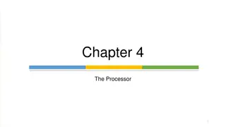
Pipeline hazards in computer architecture are classified into three categories: structural, data, and control hazards. Structural hazards occur due to conflicts in hardware resources, data hazards stem from dependencies between instructions, and control hazards arise from branching instructions. These hazards can impact the performance of pipelined processors, leading to stall cycles and reduced efficiency. Solutions to structural hazards include pipeline stalling and the introduction of pipeline bubbles to ensure proper resource utilization and instruction execution.

Download Presentation

Please find below an Image/Link to download the presentation.
The content on the website is provided AS IS for your information and personal use only. It may not be sold, licensed, or shared on other websites without obtaining consent from the author.If you encounter any issues during the download, it is possible that the publisher has removed the file from their server.
You are allowed to download the files provided on this website for personal or commercial use, subject to the condition that they are used lawfully. All files are the property of their respective owners.
The content on the website is provided AS IS for your information and personal use only. It may not be sold, licensed, or shared on other websites without obtaining consent from the author.
E N D
Presentation Transcript
Pipeline Hazards There are situations, called hazards, thatprevent the next instruction in the instruction stream from executing during its designatedcycle There are three classes of hazards Structural hazard Data hazard Branch hazard Structural Hazards. They arise from resource conflicts when the hardware cannot support all possible combinations of instructions in simultaneous overlapped execution. Data Hazards. They arise when an instruction depends on the result of a previous instruction in a way that is exposed by the overlapping of instructions in the pipeline. Control Hazards.They arise from the pipelining of branches and other instructions that change the PC.
What Makes PipeliningHard? Power failing, Arithmetic overflow, I/O devicerequest, OS call, Page fault
PipelineHazards Structural hazard Resource conflicts when the hardware cannot support all possible combination of instructionssimultaneously Data hazard An instruction depends on the results of a previous instruction Branch hazard Instructions that change thePC
Structuralhazard Some pipeline processors have shared a single- memory pipeline for data andinstructions
Single Memory is a Structural Hazard Time (clock cycles) I n s t r. M M Reg U AL Reg Load Instr 1 M M Reg U AL Reg M M Reg U AL Reg Instr 2 O r d e M M Reg U AL Reg Instr 3 M M Reg U AL Reg Instr 4 rCan t read same memory twice in same clock cycle
Structuralhazard Memory data fetch requires on FI and FO S1 S2 S5 S3 S4 Fetch Instruction (FI) Decode Instruction (DI) Time 1 2 3 Fetch Operand (FO) Execution Instruction (EI) Write Operand (WO) S1 4 5 S2 1 2 3 4 5 S3 1 2 3 4 5 S4 1 2 3 4 5 S5 1 2 3 4 5
Structuralhazard To solve this hazard, we stall the pipeline until the resource is feed A stall is commonly called pipeline bubble, since it floats through the pipeline taking space but carry no useful work
Structural Hazards limit performance Example: if 1.3 memory accesses per instruction (30% of instructions execute loads and stores) and only one memory access per cycle then Average CPI Otherwise datapath resource is more than 100% utilized Structural Hazard Solution: Add more Hardware 1.3
Structural hazard Fetch Instruction (FI) Decode Instruction (DI) Time Fetch Operand (FO) Execution Instruction (EI) Write Operand (WO)
Data hazard Example: ADD SUB AND OR XOR R1R2+R3 R4R1-R5 R6R1 AND R7 R8R1 OR R9 R10R1 XOR R11
Datahazard FO: fetch data value WO: store the executedvalue S1 S2 S3 S4 S5 Fetch Instruction (FI) Decode Instruction (DI) Time Fetch Operand (FO) Execution Instruction (EI) Write Operand (WO)
Datahazard Delay load approach inserts a no-operation instruction to avoid the data conflict ADD No-op No-op SUB AND OR XOR R1 R2+R3 R4R1-R5 R6R1 AND R7 R8R1 OR R9 R10R1 XOR R11
Datahazard It can be further solved by a simple hardware technique called forwarding (also called bypassing or short-circuiting) The insight in forwarding is that the result is not really needed by SUB until the ADD executecompletely If the forwarding hardware detects that the previous ALU operation has written the register corresponding to a source for the current ALU operation, control logic selects the results in ALU instead of from memory
Data HazardClassification Three types of data hazards RAW : WAW : Write AfterWrite WAR : Write After Read Read After Write RAR : Read After Read Is this a hazard?
Read After Write(RAW) A read after write (RAW) data hazard refers to a situation where an instruction refers to a result that has not yet been calculated or retrieved. This can occur because even though an instruction is executed after a previous instruction, the previous instruction has processed through the pipeline. not been completely example: i1. i2. R2 <- R1 + R3 R2 + R3 R4 <-
Write After Read(WAR) Awrite after read (WAR) data hazard represents a problem with concurrent execution. For example: i1. i2. R4 <- R1 + R5 R5 <- R1 + R2
Write After Write(WAW) A write after write (WAW) data hazard may occur in a concurrent executionenvironment. example: i1. i2. R2 <- R4 + R7 R2 <- R1 + R3 We must delay the WB (Write Back) of i2 until the execution ofi1
Branch hazards Branch hazards can cause a greater performance loss for pipelines When a branch instruction is executed, it may or may not change thePC If a branch changes the PC to its target address, it is a taken branch Otherwise, it is untaken
Branchhazards There are FOUR schemes to handle branch hazards Freeze scheme Predict-untaken scheme Predict-taken scheme Delayed branch
5-StagePipelining Fetch Instruction (FI) Decode Instruction (DI) Time 1 2 3 Fetch Operand (FO) Execution Instruction (EI) Write Operand (WO) S1 4 5 S2 1 2 3 4 5 S3 1 2 3 4 5 S4 1 2 3 4 5 S5 1 2 3 4 5
BranchUntaken (Freezeapproach) The simplest method of dealing with branches is to redo the fetch followinga branch Fetch Instruction (FI) Decode Instruction (DI) Fetch Operand (FO) Execution Instruction (EI) Write Operand (WO)
BranchTaken (Freezeapproach) The simplest method of dealing with branches is to redo the fetch following abranch Fetch Instruction (FI) Decode Instruction (DI) Fetch Operand (FO) Execution Instruction (EI) Write Operand (WO)
BranchTaken (Freezeapproach) The simplest scheme to handle branches is to freeze the pipeline holding or deleting any instructions after the branch until the branch destination isknown The attractiveness of this solution liesprimarily in its simplicity both for hardware and software
BranchHazards (Predicted-untaken) A higher performance, and only slightly more complex, scheme is to treat every branch asnot taken It is implemented by continuing to fetch instructions as if the branch were normalinstruction The pipeline looks the same if the branch is not taken If the branch is taken, we need to redo the fetch instruction
BranchUntaken (Predicted-untaken) Fetch Instruction (FI) Decode Instruction (DI) Time Fetch Operand (FO) Execution Instruction (EI) Write Operand (WO)
BranchTaken (Predicted-untaken) Fetch Instruction (FI) Decode Instruction (DI) Fetch Operand (FO) Execution Instruction (EI) Write Operand (WO)
BranchTaken (Predicted-taken) An alternative scheme is to treat every branch as taken As soon as the branch is decoded and the target address is computed, we assume the branch to be taken and begin fetching and executing the target
BranchUntaken (Predicted-taken) Fetch Instruction (FI) Decode Instruction (DI) Fetch Operand (FO) Execution Instruction (EI) Write Operand (WO)
Branchtaken (Predicted-taken) Fetch Instruction (FI) Decode Instruction (DI) Fetch Operand (FO) Execution Instruction (EI) Write Operand (WO)
DelayedBranch Afourth scheme in use in some processors is called delayed branch It is done in compiler time. It modifies the code The general format is: branch instruction Delay slot branch target iftaken
DelayedBranch Optimal
Delayed Branch If the optimal isnot available: (b)Act like predict-taken (in complier way) (c)Act like predict-untaken (in complier way)
DelayedBranch Delayed Branch is limited by (1)the restrictions on the instructions that are scheduled into the delay slots (for example: another branch cannot bescheduled) (2)our ability to predict at compile time whether a branch is likely to be taken or not
Branch Prediction A pipeline with branch prediction uses some additional logic to guess the outcome of a conditional branch instruction before it isexecuted
BranchPrediction Various techniques can be used to predict whether a branch will be taken ornot: Prediction nevertaken Prediction alwaystaken Prediction byopcode Branch historytable The first three approaches are static: they do not depend on the execution history up to the time of the conditional branch instruction. The last approach is dynamic: they depend on the execution history.
Important Pipeline Characteristics Latency Time required for an instruction to propagate through thepipeline Based on the Number of Stages * Cycle Time Dominant if there are lots of exceptions / hazards, i.e. we have to constantly be re-filling thepipeline Throughput The rate at which instructions can start and finish Dominant if there are few exceptions and hazards, i.e. the pipeline stays mostlyfull Note we need an increased memory bandwidth over the non-pipelinedprocessor 58
Exceptions 59 An exception is when the normal execution order of instructions ischanged. names: Interrupt Fault Exception Examples: I/O device request Invoking OS service Page Fault Malfunction Undefinedinstruction Overflow/Arithmetic Anomaly Etc! This has many
Eliminating hazards- Pipeline bubbling Bubbling the p ip e line , also knownas a p ipe line b re a k or a p ipe line s ta ll, is amethod for preventing data, structural, and branch hazards fromoccurring. instructions are fetched, control logic determines whether a hazard could/will occur . If this is true, then the control logic inserts NOPs into the pipeline. Thus, before the next instruction (which would cause the hazard) is executed, the previous one will have had sufficient time to complete and prevent the hazard.
No: of NOPs = stages inpipeline If the number of NOPs is equal to the number of stages in the pipeline, the processor has been cleared of all instructions and can proceed free from hazards. All forms of stalling introduce a delay before the processor can resume execution.


")
")
")