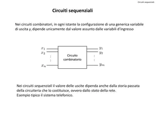
Operational Amplifier (Op-Amp) Comparator Circuits
Comparator Circuits
www.pfnicholls.com
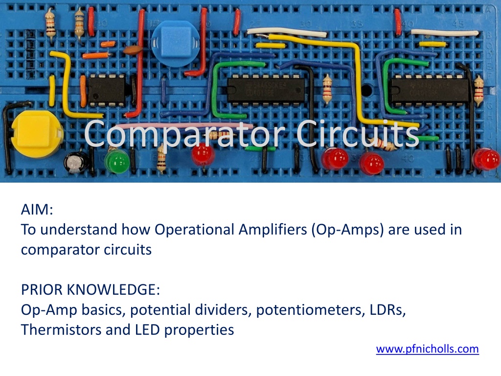
AIM:
To understand how Operational Amplifiers (Op-Amps) are used in
comparator circuits
PRIOR KNOWLEDGE:
Op-Amp basics, potential dividers, potentiometers, LDRs,
Thermistors and LED properties
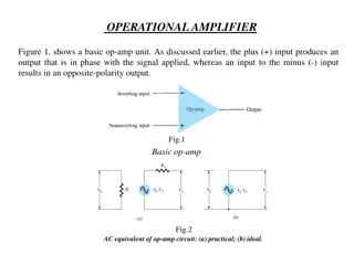
Op-Amp Basics
•
An Op-Amp used as a
comparator has two inputs
called:
o
the Non-Inverting input (+)
o
the Inverting input (-)
•
In reality, the output of a
comparator is either
ON
or
OFF
.
•
The comparator circuit takes analogue inputs and produces a
digital output. It is a 1-Bit Digital to Analogue Convertor (DAC)
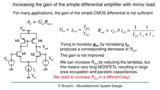
Tech point:
The difference between the inputs is multiplied by the open loop gain which is usually around 10
6
. Therefore, unless
the inputs are within a few microvolts of each other, the output saturates close to either the positive or negative supply rail.
Learn
These
Names
Comparator Basics
The basic functionality is:
Non-Inverting
input is a HIGHER voltage than the
Inverting input
O
utput will be ON
(or at least as close to the positive supply as possible)
Non-Inverting
input is a LOWER voltage than the Inverting input
Output will be OFF
(or at least as close to the negative supply as possible)
You just have to know this …
it is what they do
A note about real comparators
Op-Amps such as the 741 or the 081 are ideal as
comparators but it is important to remember the
following points:
•
The maximum output voltage is about 2 volts
less than the positive power supply.
•
The minimum output voltage is about 2 volts
above the negative power supply.
•
Using a ±15
V supply gives outputs of ±13
V.
Using a 0
V and 9
V supply gives outputs of 2
V
and 7
V.
•
The Op-Amps can source and sink only about
10
mA which is enough to drive an LED but not
a motor or a relay.
Example Circuit 1
•
The Non-Inverting input is a higher voltage than the Inverting
input and therefore the Output will be ON
•
The positive power supply is +9
V, the Output will be +7
V
To make the Output go
OFF, the Non-Inverting
input must be reduced
so that it is less than 2V
ON
OR … increasing the
Inverting input so that it
is greater than 4V will
also turn the Output OFF
Example Circuit 2
•
The Non-Inverting input (because it is negative) is less than
the Inverting input and so the Output is “OFF”.
•
In this case the negative power supply is -12
V therefore the
Output is -10
V and OFF is not a very accurate description …
•
The Output changes
from ON to OFF or vice
versa when the two
inputs are
equal.
•
If the Non-Inverting
input is slowly increased,
the Output comes ON
when the Non-Inverting
input reaches 3
V
OFF
Using an LDR
•
The 4.5
V at the Inverting input from the fixed potential divider
does not change with light level and is the REFERENCE voltage.
•
The voltage at the Non-Inverting input changes as the light
level changes. When it gets brighter, V
+
increases.
In the DARK the resistance for
the LDR is high and the voltage
at the Non-Inverting input will
be very low. The Output is OFF.
AS the light level increases the
resistance of the LDR
decreases, the Non-Inverting
input voltage increases. The
Output comes ON.
A Thermistor could be
used instead of the LDR
to make a temperature
sensitive circuit
Using a potentiometer
•
The Reference Voltage is provided by a potentiometer
•
The temperature at which the Output switches from ON to
OFF can be adjusted by changing the Reference Voltage
When it is COLD the resistance of
the thermistor is HIGH and the
Non-Inverting input voltage is
HIGH meaning the Output is ON
When it is HOT the resistance of
the thermistor is LOW, therefore
the Non-Inverting input voltage
is LOW, the Output is OFF
Increasing the Reference Voltage means the
Output changes at a lower temperature
Example Circuit Design
The challenge:
Design
a circuit so that the
LED comes ON when
the light level drops
below 200Lux.
•
Chose
to make resistor R2 an LDR. When light level drops,
resistance of the LDR increases and so V
+
increases and LED turns
on as required.
•
At 200 Lux, Resistance of LDR (R2) = 1k5
Ω
so chose a
similar value
for R1 … choose 2k2 as it is convenient.
•
R1:R2 = 2k2:1k5 therefore, R3:R4 must be in
same ratio
. It is better
to use large values (less current flows from battery)
•
Choose R3 = 220
k
Ω
and R4 = 150
k
Ω
.
•
At 200 Lux, V
+
= V
-
at the point where the LED switches ON or OFF
Range Detector
•
When V
in
< 3
V Output
1 and 2 are both HIGH
and the LED is OFF as
there is no potential
difference.
•
When 3
V < V
in
< 6
V
Output 1 is ON and
Output 2 is OFF and
the LED is ON due to
the potential
difference
•
When V
in
> 6
V both
Outputs are OFF and
the LED is OFF
The LED is only ON
when V
in
is in the
range 3V to 6V
V
in
could be the output from a
potential divider with an LDR or a
Thermistor for example
Sink and Source
When it is COLD the Non-
Inverting input is HIGH
and the Output is +13
V.
The Op-Amp
sources
current through the Red
LED to 0
V
When it is HOT the Non-
Inverting input is LOW and
the Output is -13
V.
Current flows from 0
V,
through the Green LED
and down to the -15
V
supply rail. The Op-Amp
sinks
current
Note that the Output
will be ±13
V but the
LEDs are both
connected to 0
V
Cold = RED
Hot = GREEN
Tech point: The output can provide current (source) or allow current to flow into
the output (sink). The term output appears to be incorrect if current flows into the
output. The output is the output not because current flows out but because it
controls the output transducers (the LED) by either sinking or sourcing current.
Summary
•
The inputs of a comparator are the Non-Inverting input (+)
and the Inverting input (
)
•
The output is either close to the positive supply (ON) or close
to the negative supply (OFF)
•
If the Non-Inverting input is greater than the Inverting input
then the output is ON / HIGH / fully positive
•
If the Non-Inverting input is less than the Inverting input then
the output is OFF / LOW / fully negative / close to zero
•
The output can SINK or SOURCE about 10mA of current
•
Technically V
out
= A
0
(V
+
V
) where A
0
10
6
Questions
1.
For a comparator run off a ±15
V power supply, what are the
two possible output voltages?
2.
For the comparator in question 1, what is the output voltage
when V
+
= 6
V and V
= 4
V?
3.
For the comparator in question 1, what is the output voltage
when V
+
= 6
V and V
= 8
V?
4.
For the comparator in question 1, what is the output voltage
when V
+
=
-
6
V and V
= - 4
V?
5.
For a comparator run off a 5
V and 0
V power supply, what are
the two possible output voltages?
6.
What are the possible problems when using the comparator
in Qn5?
Answers
1.
+13
V and
-13
V
2.
+13
V: the Non-Inverting input is bigger than the Inverting
input
3.
-13
V: the Non-Inverting input is smaller that the Inverting
input
4.
-13
V: the Non-Inverting input is smaller that the Inverting
input even though they are both negative because -6
V is less
than -4
V
5.
3
V and 2
V
6.
The two output voltages are very similar, a logic circuit would
struggle to reliably distinguish between these two states and
may well read both 2
V and 3
V as logic 1
Operational Amplifiers (Op-Amps) are commonly used in comparator circuits to convert analog inputs to digital outputs. In comparator circuits, the Non-Inverting input being higher or lower than the Inverting input determines whether the output is ON or OFF. Real comparators like the 741 or 081 have specific operational characteristics to consider. This guide explores Op-Amp basics, comparator functionality, example circuits, and important considerations when using Op-Amps in comparator applications.

Download Presentation

Please find below an Image/Link to download the presentation.
The content on the website is provided AS IS for your information and personal use only. It may not be sold, licensed, or shared on other websites without obtaining consent from the author.If you encounter any issues during the download, it is possible that the publisher has removed the file from their server.
You are allowed to download the files provided on this website for personal or commercial use, subject to the condition that they are used lawfully. All files are the property of their respective owners.
The content on the website is provided AS IS for your information and personal use only. It may not be sold, licensed, or shared on other websites without obtaining consent from the author.
E N D
Presentation Transcript
Comparator Circuits AIM: To understand how Operational Amplifiers (Op-Amps) are used in comparator circuits PRIOR KNOWLEDGE: Op-Amp basics, potential dividers, potentiometers, LDRs, Thermistors and LED properties www.pfnicholls.com
Op-Amp Basics An Op-Amp used as a comparator has two inputs called: o the Non-Inverting input (+) o the Inverting input (-) In reality, the output of a comparator is either ON or OFF. Learn These Names The comparator circuit takes analogue inputs and produces a digital output. It is a 1-Bit Digital to Analogue Convertor (DAC) Tech point: The difference between the inputs is multiplied by the open loop gain which is usually around 106. Therefore, unless the inputs are within a few microvolts of each other, the output saturates close to either the positive or negative supply rail.
Comparator Basics The basic functionality is: Non-Inverting input is a HIGHER voltage than the Inverting input Output will be ON (or at least as close to the positive supply as possible) Non-Inverting input is a LOWER voltage than the Inverting input Output will be OFF (or at least as close to the negative supply as possible) You just have to know this it is what they do
A note about real comparators Op-Amps such as the 741 or the 081 are ideal as comparators but it is important to remember the following points: The maximum output voltage is about 2 volts less than the positive power supply. The minimum output voltage is about 2 volts above the negative power supply. Using a 15V supply gives outputs of 13V. Using a 0V and 9V supply gives outputs of 2V and 7V. The Op-Amps can source and sink only about 10mA which is enough to drive an LED but not a motor or a relay.
Example Circuit 1 To make the Output go OFF, the Non-Inverting input must be reduced so that it is less than 2V OR increasing the Inverting input so that it is greater than 4V will also turn the Output OFF ON The Non-Inverting input is a higher voltage than the Inverting input and therefore the Output will be ON The positive power supply is +9V, the Output will be +7V
Example Circuit 2 The Output changes from ON to OFF or vice versa when the two inputs are equal. If the Non-Inverting input is slowly increased, the Output comes ON when the Non-Inverting input reaches 3V OFF The Non-Inverting input (because it is negative) is less than the Inverting input and so the Output is OFF . In this case the negative power supply is -12V therefore the Output is -10V and OFF is not a very accurate description
A Thermistor could be used instead of the LDR to make a temperature sensitive circuit Using an LDR In the DARK the resistance for the LDR is high and the voltage at the Non-Inverting input will be very low. The Output is OFF. AS the light level increases the resistance of the LDR decreases, the Non-Inverting input voltage increases. The Output comes ON. The 4.5V at the Inverting input from the fixed potential divider does not change with light level and is the REFERENCE voltage. The voltage at the Non-Inverting input changes as the light level changes. When it gets brighter, V+ increases.
Using a potentiometer When it is COLD the resistance of the thermistor is HIGH and the Non-Inverting input voltage is HIGH meaning the Output is ON When it is HOT the resistance of the thermistor is LOW, therefore the Non-Inverting input voltage is LOW, the Output is OFF Increasing the Reference Voltage means the Output changes at a lower temperature The Reference Voltage is provided by a potentiometer The temperature at which the Output switches from ON to OFF can be adjusted by changing the Reference Voltage
Example Circuit Design The challenge: Design a circuit so that the LED comes ON when the light level drops below 200Lux. Chose to make resistor R2 an LDR. When light level drops, resistance of the LDR increases and so V+ increases and LED turns on as required. At 200 Lux, Resistance of LDR (R2) = 1k5 so chose a similar value for R1 choose 2k2 as it is convenient. R1:R2 = 2k2:1k5 therefore, R3:R4 must be in same ratio. It is better to use large values (less current flows from battery) Choose R3 = 220k and R4 = 150k . At 200 Lux, V+ = V- at the point where the LED switches ON or OFF
Range Detector When Vin < 3V Output 1 and 2 are both HIGH and the LED is OFF as there is no potential difference. When 3V < Vin < 6V Output 1 is ON and Output 2 is OFF and the LED is ON due to the potential difference When Vin > 6V both Outputs are OFF and the LED is OFF The LED is only ON when Vin is in the range 3V to 6V Vin could be the output from a potential divider with an LDR or a Thermistor for example
Sink and Source When it is COLD the Non- Inverting input is HIGH and the Output is +13V. The Op-Amp sources current through the Red LED to 0V When it is HOT the Non- Inverting input is LOW and the Output is -13V. Note that the Output will be 13V but the LEDs are both connected to 0V Current flows from 0V, through the Green LED and down to the -15V supply rail. The Op-Amp sinks current Cold = RED Hot = GREEN Tech point: The output can provide current (source) or allow current to flow into the output (sink). The term output appears to be incorrect if current flows into the output. The output is the output not because current flows out but because it controls the output transducers (the LED) by either sinking or sourcing current.
Summary The inputs of a comparator are the Non-Inverting input (+) and the Inverting input ( ) The output is either close to the positive supply (ON) or close to the negative supply (OFF) If the Non-Inverting input is greater than the Inverting input then the output is ON / HIGH / fully positive If the Non-Inverting input is less than the Inverting input then the output is OFF / LOW / fully negative / close to zero The output can SINK or SOURCE about 10mA of current Technically Vout = A0 (V+ V ) where A0 106
Questions 1. For a comparator run off a 15V power supply, what are the two possible output voltages? 2. For the comparator in question 1, what is the output voltage when V+ = 6V and V = 4V? 3. For the comparator in question 1, what is the output voltage when V+ = 6V and V = 8V? 4. For the comparator in question 1, what is the output voltage when V+ = - 6V and V = - 4V? 5. For a comparator run off a 5V and 0V power supply, what are the two possible output voltages? 6. What are the possible problems when using the comparator in Qn5?
Answers 1. +13V and -13V 2. +13V: the Non-Inverting input is bigger than the Inverting input 3. -13V: the Non-Inverting input is smaller that the Inverting input 4. -13V: the Non-Inverting input is smaller that the Inverting input even though they are both negative because -6V is less than -4V 5. 3V and 2V 6. The two output voltages are very similar, a logic circuit would struggle to reliably distinguish between these two states and may well read both 2V and 3V as logic 1