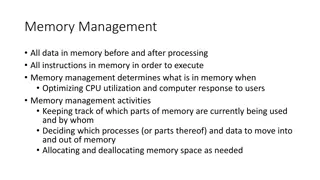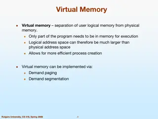
Optimizing Memory Management in Mobile Environments
Explore how Memory Management in Mobile Environments (MMM) technology addresses challenges like narrow bandwidth, unstable connectivity, and battery limitations. Learn about MMM architecture, concepts, and benefits such as faster applications, efficient communication, and local data availability.

Download Presentation

Please find below an Image/Link to download the presentation.
The content on the website is provided AS IS for your information and personal use only. It may not be sold, licensed, or shared on other websites without obtaining consent from the author. If you encounter any issues during the download, it is possible that the publisher has removed the file from their server.
You are allowed to download the files provided on this website for personal or commercial use, subject to the condition that they are used lawfully. All files are the property of their respective owners.
The content on the website is provided AS IS for your information and personal use only. It may not be sold, licensed, or shared on other websites without obtaining consent from the author.
E N D
Presentation Transcript
Kanika Chawla Parth Shah Sowmith Boyanpalli MEMORY MANAGEMENT IN MOBILE ENVIRONMENT
CITATION Shigemori Yokoyama, Takahiro Okuda, Tadanori Mizuno and Takashi Watanabe, A Memory Management Architecture for a Mobile Computing Environment . 2
MOTIVATION Today we can communicate using our mobile phones even in remote areas. But certain challenges still remain Narrow bandwidth of wireless communication Unstable connectivity Limitations of battery at mobile terminals 3
THE MMM TECHNOLOGY Above problems solved by controlling a part of mobile terminal s memory and a part of server s memory which are common to each other. Achieves the following: Synchronization of common data between mobile terminal and server Increase in processing speed Reduction in communication cost Easy programming of applications Power reduction 4
MMM ARCHITECTURE Common memory used Can be accessed by both mobile terminal and server 5
MMM ARCHITECTURE Three main concepts used in the new MMM architecture are: Cache memory: data is fetched from remote location and stored in local memory for easy access Distributed shared memory: common address spaces are at physically distinct locations but have the same address. Virtual memory: a part of common memory space of the server is used as virtual memory for the mobile terminal. 6
WHAT CAN BE ACHIEVED USING MMM Applications can run faster Do not need to program the network aspects to read/write from the server All data available locally Communication is more efficient Only necessary data being communicated at necessary time This technique can be implemented using additional hardware of convectional circuits 7
MEMORY MANAGEMNET SYSTEMS The memory is managed using the following 5 key points: Memory lines and control status field Memory control status field and line status Memory access and line transfer control Resolution of line access conflict Control of communication failure 8
MEMORY LINES AND CONTROL STATUS FIELD Memory is divided into fixed areas called lines Line sizes are between 16 Bytes 4096 Bytes Line unit handles the memory mapping between mobile terminal and server Lines are further divided into blocks, where memory write back is handled Block sizes are between 16 Bytes 1024 Bytes Further, The Control Status Fields control the memory line status. Ensures memory consistency i.e. lines on mobile terminal and server with same line number should have same data 9
MEMORY CONTROL STATUS FIELD AND LINE STATUS Control status field is divided into three bits: Valid bit: shows if the line is valid(1) or invalid Copy bit: whether the line has been copied back to server/mobile terminal(1) or not Dirty bits: whether write operation has been performed on the blocks. 10
MEMORY ACCESS AN DLINE TRANSFER CONTROL In case of memory access, The kind of memory operation is determined by the kind of memory access The next memory line status is determined by current memory line status The line transfer control and related line status control are performed in memory exception interrupt(MEI) MEI is invoked by memory access 11
MEMORY EXCEPTION INTERRUPT Communications between a mobile terminal and server to transfer the lines are executed in a memory exception interrupt Taking some sample cases for memory access and line transfer control 12
SAMPLE MEMORY ACCESSES If status is VC(m)= 100 Content is valid as V = 1, i.e. read/write has been successfully performed on mobile terminal It has not been copied to the server yet as C = 0 If line status is invalid i.e. V(m) = 0 or old VC(m) = 11 The MEI occurs to achieve memory consistency Exception routines on mobile terminal and server communicate to transfer designated line When line is requested from mobile terminal , a remote interrupt occurs on the server 13
For V(m)=0 , content is transferred to the mobile terminal For VC(m)=11, then D(s) bits are further inspected if D(s) bit of a block is 1 then corresponding data is transferred If all D(s) are 0 then no transfer because no alterations have been done VC(s) is then set to 11 and interrupt routine is terminated 14
In mobile terminals interrupt routine , during the transfer of data from server, the line status becomes VCD(m) = 100 which corresponds to the newest line Again if the write operation is performed D(m) bits are set 15
RESOLUTION OF LINE ACCESS CONFLICT A deadlock situation occurs if the mobile terminal and server request the same line at the same time. To prevent this the remote interrupt is turned off between the memory exception and completion of the first instructions execution after the end of interruption By this method when the same line is used the memory line is accessed alternatively between the mobile terminal and the server 16
CONTROL OF COMMUNICATION FAILURE In the case of exception communication should be established. If the communication fails the control program reports the status of memory to the application 17
EXPERIMENTAL SETUP MMM system can be realized by using a processor with a standard architecture 18
COMPARISON OF MMM AND A CONVENTIONAL MEMORY SYSTEM ON A MOBILE TERMINAL 20
COMPARISON OF MMM AND A CONVENTIONAL MEMORY SYSTEM ON A SERVER 21
Limitations Data in the paper is redundant with lot of information repeated It doesn t discuss any fault tolerant 22
CONCLUSION MMM is the most preferable memory architecture for mobile terminals and servers . Introducing MMM achieves synchronisation of common data on the moobile terminal and server. The applcation executes faster and efficiency of communication system increases by decreasing the communication cost and saving power. Prefetching multiple lines increases the efficiency. 23
A Distributed Cache Management Architecture for Mobile Computing Environments Presented at 2009 IEEE International Advance Computing Conference (IACC 2009) By: G. Anandharaj, Dr. R. Anitha 24
Introduction Presents an effective technique to improve performance in a mobile environment Caches frequently accessed data items on client side Reduces data access latency as data access request can satisfied from the local cache or active node cache 25
Introduction Cache management in mobile environment includes following issues to be addresses: Cache discovery algorithm :- Efficiently discover, select and deliver requested data from neighboring nodes Cache admission control: - Decides what data to cache Cache consistency algorithm: - Ensures no stale data are present Cache replacement algorithm: - Decides which data to replace 26
Distributed Cache Management Architecture (CCCM) Goal: to reduce the caching overhead and provide optimal consistency and replacement. To improve the network utilization, reduce the search latency, bandwidth and energy consumption. 27
Network Model Mobile Computing Network Geographic area divided into cells Cells consists of Base Station (BS) and Mobile Terminals (MT) Intra-cell and Inter-cell communication managed by BSs. MTs communicate with BS by wireless network Mobile network with n cells C1, C2, , Cn For each cell Ci, DSi is database server that keep pieces of information, that is accessed by other systems S1, S2, Sm are the clients in each cell. 28
Tree Based Database Architecture The different DSs may be considered as mobile networks owned by different service providers. Communication between DSs takes place only through their root databases Each cell is controlled by a DS2. Each DS2 is co located with a BS, which performs query processing on a query arrival. A number of DS2s are clustered into one DS1and several DSIs are connected to a single DSO. The DSO maintains a location profile for each mobile client currently residing in its service area. It consists of a record for each client in the entire mobile system. 30
Organization of Databases Index file & Data File Index file points to the location profile of mobile clients in data file Client location profile contains pointer to DS of one level down the hierarchy of the client Index File Data File DS 31
Location Update Procedure 1. Client C1 moves from one DS2 to another DS2 Sends request message to associated DS2 which routes it to DS1 2. If DS1 remains same then old DS2 is updated with new DS2, old DS2 gets cancellation message If DS1 changes, DS0 updates the old DS1 with new DS1, old DS1 gets cancellation message, New entry in DS2 3. Old DS2 removes the entry and sends the location profile to new DS2 4. New DS2 adds new record and stores the location profile 32
Distributed Cache Management Architecture (DCMA) Cache Placement Neighboring active slides form a cooperative cache system In case of data miss in the local cache, client searches in its zone. Active node decided based on weight Wi = (BWi + SPi + CRi ) / ALi Vector W = {Si, Wi} All the nodes above a cutoff are Active nodes Sk, W > Beta Database server caches data into active nodes
Cache Discovery Algorithm Determines where the requested data is located The list Sk is broadcasted to all clients, once it is created For a miss, node sends request packet to active nodes Active node having data sends ack packet to sender node Ack contain Timestamp and Weight Based on this information, sender node requests data from best active client with a confirm packet Best client sends requested data
Cache Consistency Algorithm Update message is sent to the nearest client in list Sk Ack sent and forwards update to next client in list Procedure repeats for all nodes until ack received The sender propagates the data with new timestamp to all clients sending ack
Cache Replacement Algorithm Least Relevant Value replacement policy Based on: Access probability Distance: Caches data for farther node; saves bandwidth and reduces latency Size: Larger cache block makes room for more data
average query latency as a function of Tquery. 39
Average End-to-end Delay For Different Traffic Rates 40
Average Throughput Received For Different Cache Sizes 41
Pitfalls 1. No fault tolerant mechanism 2. May degrade performance
Conclusion DCMA (Distributed cache management architecture ) includes cache placement, discovery , consistency and replacement techniques It provided efficient technique for location update in the case of moving clients. It achieves lower latency , reduced packet loss, reduced network bandwidth consumption, reduced data server workload. 43


=0 , content is transferred to the mobile")