Optical Fiber Link Systems for Data Transmission Design Guide
Explore the principles of optical power budget and rise time budget in light wave systems for designing efficient point-to-point links. Understand system considerations, architecture, and major components like transmitters, regenerators, and receivers. Learn to apply subject knowledge in designing reliable long haul systems.

Download Presentation

Please find below an Image/Link to download the presentation.
The content on the website is provided AS IS for your information and personal use only. It may not be sold, licensed, or shared on other websites without obtaining consent from the author. Download presentation by click this link. If you encounter any issues during the download, it is possible that the publisher has removed the file from their server.
E N D
Presentation Transcript
UNIT II: light wave systems (6 L) System architectures, Point-to-Point links: system considerations, Design guide lines: optical power budget, rise time budget, Long haul systems Objective To apply subject understanding in Link Design. Course Outcome Perform Link power budget and Rise Time Budget by proper selection of components and check its viability.
(Remember) Arrange, Define, Duplicate, Label, List, Memorize, Name, Order, Recognize, Relate, Recall, Repeat, Reproduce and State. (Explain) Classify, Describe, Discuss, Explain, Express, Identify, Indicate, Locate, Recognize, Report, Restate, Review, Select, Translate. (Apply) Apply, Choose, Demonstrate, Dramatize, Employ, Illustrate, Interpret, Operate, Practice, Schedule, Sketch, Solve, Use, Write. (Analysis) Analyze, Appraise, Calculate, Categorize, Compare, Contrast, Criticize, Differentiate, Discriminate, Distinguish, Examine, Experiment, Question, Test. (Synthesis) Arrange, Assemble, Collect, Compose, Construct, Create, Design, Develop, Formulate, Manage, Organize, Plan, Prepare, Propose, Set up, Write. (Evaluation) Appraise, Argue, Assess, Attach, Choose Compare, Defend Estimate, Judge, Predict, Rate, Core, Select, Support, Value, Evaluate.
The system should be able to adopt new technology as we should be able to accommodate higher data rates with least possible changes
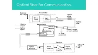
Major elements of an optical fiber link Transmitter Regenerator Receiver
System Block Diagram Transmitter Optical splice Drive circuit Optical source Source Connector Optical coupler Optical Rx Optical-to- electronics Optical Tx Regenerator Fibre Optical detector Optical amplifier Sink Receiver Their main role is to transport information, in the form of digital bit stream, from one place to another with high accuracy. The length of the link can vary from less than a kilometer to thousands of kilometers, depending on the application required.
Source Source coding Modulation Multiplexing Modulation Frequency Time Analogue Digital External Internal Pulse shaping Channel coding Encryption etc.
Regenerator Regenerator is a device to overcome attenuation problems. Electronic regeneratorregenerates signals by first converting optical signals to electrical signals. The electrical signal is regenerated, converted back to optical, and further injected into the fiber. On WDM systems, each wavelength requires its own opto-electric amplifier, an expensive proposition if there are many wavelengths.
As light travels down a fiber, it loses power, and the sharp transitions (representing binary data - or 1's and 0's) of the digital signal become smoothed out and loses power. This is rectified by placing amplifiers and regenerators into series with the fiber cable. An optic amplifier/repeater merely increases the power of the signal ( makes the light brighter). A regeneration station ("regen") reshape the digital signal into sharp, well-defined 1's and 0's. In general, with metro fiber routes, there are about 4 / 5 amps for every regen .
Amplifier, Regenerator and example of a metro fiber routes After a certain distance(25-100 km) it becomes necessary to compensate for fiber loss. This can be done using regenerators that restore the SNR and pulse shape but not the BER.
Amplification and Regeneration of Optical pulses The periodic regeneration is usually required to regenerate the original synchronization of signals. Complete regeneration regenerating operations with a signal viz. waveform and includes three 1. Regeneration of amplitude (amplification), 2. Regeneration of signal waveform, and, 3. Regeneration of synchronization.
Three Rs of complete Regeneration of Signals (of amplitude, signal waveform, and synchronization)
Receiver Sampler & detector Pre-detection filtering 1st-stage amplifier 2nd-stage amplifier Demultiplexer Equalizer Demodulator Decoder Decryption Output signal
Digital Links Digital Transmission Systems The simplest transmission link shown below is point-to-point link. Simple Block Diagram of Point-To-Point Link Infor- -mation source Optical trans- -mitter Optical Receiver user Optical fiber
Point-to-Point Links Key system requirements needed to analyze optical fiber links: 1. The desired (or possible) transmission distance 2. The data rate or channel bandwidth 3. The desired bit-error rate (BER) LED or laser MMF or SMF pin or APD (a) Emission wavelength (b) Spectral line width (c) Output power (d) Effective radiating area (e) Emission pattern (a) Core size (b) Core index profile (c) BW or dispersion (d) Attenuation (e) NA or MFD (a) Responsivity (b) Operating (c) Speed (d) Sensitivity
Selecting the Fiber Bit rate and distance are the major factors Other factors to consider: attenuation (depends on?) and distance-bandwidth product (depends on?) cost of the connectors, splicing etc. Then decide Multimode or single mode Step or graded index fiber
Based on above information, selection of optical fiber (single/multi mode) is done and following details about the fiber is required. 1.Core size 2. core refractive index profile 3. Band width or dispersion 4. Attenuation 5. NA or Mode field diameter
Selecting the Optical Source Emission wavelength depends on acceptable attenuation and dispersion Spectral line width depends on acceptable dispersion (LED wide, LASER narrow) Output power in to the fiber (LED low, LASER high) Stability, reliability and cost Driving circuit considerations
Then, (LASER/LED) and following information about the source is required. 1.Emission wavelength 2. Spectral line width 3. Output power 4. Effective radiating area 5. Emission pattern 6. Number of emitting modes. appropriate source is selected
Typical bit rates at different wavelengths LED Systems LASER Systems. Wavelength 800-900 nm (Typically Multimode Fiber) 1300 nm (Lowest dispersion) 150 Mb/s.km 2500 Mb/s.km 1500 Mb/s.km 25 Gb/s.km (InGaAsP Laser) 1550 nm (Lowest Attenuation) 1200 Mb/s.km Up to 500 Gb/s.km (Best demo)
Selecting the detector Type of detector APD: High sensitivity but complex, high bias voltage (40V or more) and expensive PIN: Simpler, thermally stable, low bias voltage (5V or less) and less expensive Responsivity (that depends on the avalanche gain & quantum efficiency) Operating wavelength and spectral selectivity Speed (capacitance) and photosensitive area Sensitivity (depends on noise and gain)
Design Considerations Link Power Budget There is enough power margin in the system to meet the given BER Rise Time Budget Each element of the link is fast enough to meet the given bit rate These two budgets give necessary conditions for satisfactory operation
Link power budget and Rise time budget are the methods to analyze working of desired system & it s performance.
System Considerations Selection of Wave Length to transmit the data decides the components which operates in this wavelength region. For example, if transmission distance is small, operating wavelength may be 800-900 nm and if it is large; the wavelength would be 1300/ 1550 nm (where low attenuation & dispersion occurs).
While selecting a photo detector, we determine, how much minimum optical power must to fall on the photo-detector to satisfy BER requirement at the specified data rate. Selection of source requires the parameters to be seen as signal dispersion, data rate, transmission distance and cost. Selection of optical fiber depends on type of source and amount of dispersion that can be tolerated.
In the Link power budget; for a specific BER, power margin between optical transmitter output and minimum receiver sensitivity is determined and then margin is allocated to connectors, splices, fiber losses etc. In Rise time budget, it is checked that the desired overall system performance is achieved or not? It determines the dispersion limitations of an optical fiber link.
So while talking about RTB, The system speed is observed limited by the factors as Transmitter rise time ttx Group velocity dispersion rise time tGVD Modal dispersion rise time tmod Receiver rise time trx 2 2 mod [ sys tx t t t = + + = + + 1. 2. 3. 4. + 2 GVD 2 1/2 ] rx + t t 2 tx 2 2 2 2 1/2 ) ] [ 44 0 / ( 350 / t t Lq B D L B 0 s ys r x Here, is the half power spectral width of the source, D is dispersion, L is length, q is a constant (ranging from 0.5- 1.0), B0 is band width of 1km length of cable.
Rise-Time Budget (1) A rise-time budget analysis determines the dispersion limitation of an optical fiber link. The total rise time tsysis the root sum square of the rise times from each contributor tito the pulse rise-time degradation: The transmitter rise time ttx The group-velocity dispersion (GVD) rise time tGVD of the fiber The modal dispersion rise time tmod of the fiber The receiver rise time trx Here Be and B0 are given in MHz, so all times are in ns.
Optical power-loss model = = + + + ystem Margin P P P ml nl L S T s R c sp f : Total loss; connectors; splices : Source power; : Rx sensitivity P P m P n T s R Try Ex: 8.1
In a fiber optic system, optical fiber loss occurs due to : o Source to fiber coupling losses o Connector loss o Splices loss o Fiber attenuation o System margin loss due to component ageing & temp. fluctuations
The link power budget provides calculation details for probable losses and additional power margin for component ageing & temp. fluctuations. The power budget equation Pd = Ps Pr Where Ps is power of the source and Pr is receiver sensitivity.
Since, power launched to fiber Pf = Pr + losses and also, Pf = .Ps ( is quantum efficiency) thus, Pf Pr = losses Or, Or, .Ps - Pr = losses Pr = .Ps losses Here Losses = m.Lc + n.Ls + .D + s
Losses = m.Lc + n.Ls + .D + s where, Lc- connector loss in dB. Ls- splice loss in dB m-No. of connectors n-No. of splices -Fiber attenuation in dB/ Km D-transmission distance in Km. s-system margin(6-8 dB)
The final power budget equation is Pd = Ps Pr = Ps ( .Ps losses) = Ps .Ps + losses = Ps (1 - ) + losses = Ps (1 - ) + m.Lc + n.Ls + .D + s So the power budget equation is Pd = Ps (1 - ) + m. Lc + n. Ls + .D + s
Power Budget Example Specify a 20-Mb/s data rate and a BER = 10 9. With a Si pin photodiode at 850 nm, the required receiver input signal is 42 dBm. Select a GaAlAs LED that couples 50 mW into a 50- m core diameter fiber flylead. Assume a 1-dB loss occurs at each cable interface and a 6-dB system margin. The possible transmission distance L = 6 km can be found from PT = PS PR = 29 dB = 2lc + L + system margin = 2(1 dB) + L + 6 dB The link power budget can be represented graphically (see the right-hand figure).
Long-haul systems In telecommunication, the term long-haul communications has meanings: 1. In public switched networks, pertaining to circuits that span large distances, such as the circuits in inter-LATA, international communications. 2. In the military communications among users on a national or worldwide basis. the following interstate, and community,
Long-haul systems Basically; Long-haul optics refers to the transmission of visible light signals over optical fiber cable for great distances, especially without or with minimal use of repeaters. Normally, repeaters are necessary at intervals in a length of fiber optic cable to keep the signal quality from deteriorating to the point of non- usability. In long-haul optical systems, the goal is to minimize the number of repeaters per unit distance, and ideally, unnecessary. to render repeaters
Long-haul systems The long-haul communications are characterized by (a)Higher levels of users, such as the National Command Authority, (b)More stringent performance requirements, such as higher quality circuits, (c)Longer distances between users, including world wide distances, (d)Higher traffic volumes and densities, (e)Larger switches and trunk cross sections, and (f)Fixed and recoverable assets. The"Long-haul communications" usually pertains to the defense services e.g U.S. Defense Communications System.
technology communications systems reach distances that were once unheard of. Today's fiber optic transmission links transmit multiple channels of video and audio signals over a worldwide distances, and can reach high traffic volumes. This distance is made possible by a number of devices that amplify optical signals and combine larger & larger numbers of signals for transmission over a single optical fiber. Actually, Advances have in fiber optic made long-haul
A basic long-haul CATV transmission system designed to carry 77 channels of CATV VSB/AM signals for 100km in a basic point-to-point configuration.
A bidirectional application that multiplexes both L-Band and CATV VSB/AM signals. This configuration also incorporates a WDM channel at 1310nm as well as six channels in the C-Band region.
")
 Arrange, Define, Duplicate, Label, List,")


")
")