NGV PHY Simulation Overview: Channel Models and Implementations


Simulation of NGV PHY
Date:
2019-03-11
March 2019
Ioannis Sarris, u-blox
Slide 1

Authors:
Abstract
This contribution presents some aspects of NGV PHY simulation. Best
practices and reference implementations are presented for:
•
Channel models
•
Oversampling
•
Power Amplifier (PA) model
•
Phase noise
•
Carrier Frequency Offset (CFO)
•
Open source 802.11p model [1] available at
https://github.com/u-blox/ubx-v2x
Slide 2
Ioannis Sarris, u-blox
March 2019
Channel Models
Topic 1
March 2019
Ioannis Sarris, u-blox
Slide 3
Channel models
•
The Car-2-Car channel models [2] are a
good basis for the evaluation of PHY
performance under time and frequency-
selective propagation conditions
•
These are tap-delay models defined by a
sets of delay, power and Doppler spectra
•
In [2], the Doppler spectra after the 1
st
tap
are defined as “Half-Bathtub”
•
A more mathematically accurate
description would be “Asymmetric Jakes”
with limits [0,
f
d
]
March 2019
Ioannis Sarris, u-blox
Slide 4
Channel models
•
MATLAB’s
comm.RicianChannel
allows for such spectrum
definitions per channel tap
•
A reference definition is available in the ubx-v2x model
March 2019
Ioannis Sarris, u-blox
Slide 5
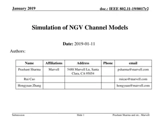
Table 1: Rural LOS Parameters
Tap1
Tap2
Tap3
Fig. Example of Doppler spectrum per channel tap for Rural LoS
Enhanced channel models
•
A set of even more challenging channel
models have been proposed in [3]
•
A reference implementation is also
available in the ubx-v2x model
March 2019
Ioannis Sarris, u-blox
Slide 6
Table 1: Rural LOS Parameters
Table 2: Urban Approaching LOS Parameters
Table 3: Crossing NLOS Parameters
Table 4: Highway LOS Parameters
Table 5: Highway NLOS Parameters
Oversampling
Topic 2
March 2019
Ioannis Sarris, u-blox
Slide 7
Oversampling
•
Contribution 19/0017r4 proposed
the use of oversampling (8x) when
simulating NGV
•
Oversampling is useful for
investigations on
•
Spectrum mask compliance
•
PA non-linearity
•
Multi Channel Operation
•
Adjacent channel rejection
March 2019
Ioannis Sarris, u-blox
Slide 8
Oversampling
•
Investigation of baseband
performance is not affected by
oversampling on its own
•
Baseband equivalence holds
•
Example: PER vs SNR
•
10 MHz vs 40 MHz
•
No significant difference in performance
observed
March 2019
Ioannis Sarris, u-blox
Slide 9
Rural LoS – 300 bytes
Power Amplifier model
Topic 3
March 2019
Ioannis Sarris, u-blox
Slide 10
Power Amplifier model
•
Model introduced in 11-00/294
•
RAPP model
•
Indicative parameters
•
p = 3
•
Output back-off (OBO) = 8 dB
March 2019
Ioannis Sarris, u-blox
Slide 11
Fig. Power amplifier model, taken from [4]
Phase noise
Topic 4
March 2019
Ioannis Sarris, u-blox
Slide 12
Phase noise
•
Usually modelled with a pole-zero
model (11-03/814r31)
•
PSD(0) = -100 dBc/Hz
•
pole frequency
f
p
= 250 kHz
•
zero frequency
f
z
= 7905.7 kHz
•
PSD(0) = -100 dBc/Hz produces a
negligible effect in PER performance
•
Higher values are more realistic
March 2019
Ioannis Sarris, u-blox
Slide 13
Carrier Frequency Offset
Topic 5
March 2019
Ioannis Sarris, u-blox
Slide 14
Carrier Frequency Offset
•
CFO is often modelled as a uniformly
distributed R.V. between -40 and 40 ppm
•
This is a very pessimistic scenario with
extreme values derived from the maximum
allowed frequency error at both ends
•
The state-of-the-art 802.11p chipsets have
frequency errors of 5ppm or less (some
even on the ppb region)
•
Also, the distribution of total CFO error is
not uniform due to the additive effect
between the error in Tx and Rx
March 2019
Ioannis Sarris, u-blox
Slide 15
Conclusions
•
Some recommendations for 11p/NGV PHY simulation were given from a
V2X silicon provider’s perspective
•
Our goal is to help aligning our simulation methodologies to be able to take
the best possible decisions for 11bd
•
Ideally we should match the real-world performance as closely as possible
while maintaining a low simulation complexity
•
All information presented here is available for evaluation as open source
software
•
Comments or proposals for improvement of this work are always welcome
Slide 16
Ioannis Sarris, u-blox
March 2019
References
[1] I. Sarris, “V2X Simulation Model,”
IEEE 802.11-18/1480r0.
[2] M. Kahn, "IEEE 802.11 Regulatory SC DSRC Coexistence Tiger Team V2V Radio
Channel Models," IEEE 802.11-14/0259r0.
[3] P. Alexander et. al, "Cohda-GM V2X Fading Channels".
[4] E. Perahia et. al, “Next Generation Wireless LANs”.
Slide 17
Ioannis Sarris, u-blox
March 2019
doc.: IEEE 802.11-yy/xxxxr0
Month Year
John Doe, Some Company
Page
This document delves into the simulation of NGV PHY, focusing on channel models, oversampling, power amplifier modeling, and more. It presents best practices, reference implementations, and detailed analysis of Doppler spectra and channel tap definitions for PHY performance evaluation.

Download Presentation

Please find below an Image/Link to download the presentation.
The content on the website is provided AS IS for your information and personal use only. It may not be sold, licensed, or shared on other websites without obtaining consent from the author.If you encounter any issues during the download, it is possible that the publisher has removed the file from their server.
You are allowed to download the files provided on this website for personal or commercial use, subject to the condition that they are used lawfully. All files are the property of their respective owners.
The content on the website is provided AS IS for your information and personal use only. It may not be sold, licensed, or shared on other websites without obtaining consent from the author.
E N D
Presentation Transcript
March 2019 doc.: IEEE 802.11-19/0311r0 Simulation of NGV PHY Date: 2019-03-11 Authors: Name Ioannis Sarris Affiliations u-blox Address Athens, Greece Phone +30 6976080735 email ioannis.sarris@u-blox.com Submission Slide 1 Ioannis Sarris, u-blox
March 2019 doc.: IEEE 802.11-19/0311r0 Abstract This contribution presents some aspects of NGV PHY simulation. Best practices and reference implementations are presented for: Channel models Oversampling Power Amplifier (PA) model Phase noise Carrier Frequency Offset (CFO) Open source 802.11p model [1] available at https://github.com/u-blox/ubx-v2x Submission Slide 2 Ioannis Sarris, u-blox
March 2019 doc.: IEEE 802.11-19/0311r0 Topic 1 Channel Models Submission Slide 3 Ioannis Sarris, u-blox
March 2019 doc.: IEEE 802.11-19/0311r0 Channel models The Car-2-Car channel models [2] are a good basis for the evaluation of PHY performance under time and frequency- selective propagation conditions These are tap-delay models defined by a sets of delay, power and Doppler spectra In [2], the Doppler spectra after the 1st tap are defined as Half-Bathtub A more mathematically accurate description would be Asymmetric Jakes with limits [0, fd] Submission Slide 4 Ioannis Sarris, u-blox
March 2019 doc.: IEEE 802.11-19/0311r0 Channel models Tap1 Tap2 Tap3 Units dB ns Hz MATLAB s comm.RicianChannel allows for such spectrum definitions per channel tap A reference definition is available in the ubx-v2x model Power Delay Doppler Profile Table 1: Rural LOS Parameters 0 0 0 -14 83 492 -17 183 -295 Static HalfBT HalfBT Tap1 Tap2 Tap3 Fig. Example of Doppler spectrum per channel tap for Rural LoS Submission Slide 5 Ioannis Sarris, u-blox
March 2019 doc.: IEEE 802.11-19/0311r0 Enhanced channel models A set of even more challenging channel models have been proposed in [3] A reference implementation is also available in the ubx-v2x model Name Power Delay Doppler Profile Tap1 0 0 0 Static Tap2 -3 220 -142 Half BT Tap3 -4 266 -542 Half BT Tap4 -7 475 -155 Half BT Tap5 -15 630 320 Half BT Units dB ns Hz Table 3: Crossing NLOS Parameters Name Power Delay Doppler Profile Tap1 0 0 0 Static Tap2 -11 167 1941 Half BT Tap3 -13 433 -1176 Half BT Tap4 -17 600 -391 Half BT Units dB ns Hz Name Power Delay Doppler Profile Tap1 0 0 0 Static Tap2 -12 84 94 Half BT Tap3 -15 183 -1176 Half BT Units dB ns Hz Table 4: Highway LOS Parameters Table 1: Rural LOS Parameters Name Power Delay Doppler Profile Tap1 0 0 0 Static Tap2 -2 100 50 Half BT Tap3 -5 500 1157 Half BT Tap4 -7 867 -2352 Half BT Tap5 -15 1152 1573 Half BT Units dB Ns Hz Name Power Delay Doppler Profile Tap1 0 0 0 Static Tap2 -11 222 224 Half BT Tap3 -13 334 1173 Half BT Tap4 -15 533 588 Half BT Units dB ns Hz Table 2: Urban Approaching LOS Parameters Table 5: Highway NLOS Parameters Submission Slide 6 Ioannis Sarris, u-blox
March 2019 doc.: IEEE 802.11-19/0311r0 Topic 2 Oversampling Submission Slide 7 Ioannis Sarris, u-blox
March 2019 doc.: IEEE 802.11-19/0311r0 Oversampling Contribution 19/0017r4 proposed the use of oversampling (8x) when simulating NGV Oversampling is useful for investigations on Spectrum mask compliance PA non-linearity Multi Channel Operation Adjacent channel rejection Submission Slide 8 Ioannis Sarris, u-blox
March 2019 doc.: IEEE 802.11-19/0311r0 Oversampling Rural LoS 300 bytes Investigation of baseband performance is not affected by oversampling on its own Baseband equivalence holds Example: PER vs SNR 10 MHz vs 40 MHz No significant difference in performance observed 10 MHz (no oversampling) 40 MHz (oversampling x4) Submission Slide 9 Ioannis Sarris, u-blox
March 2019 doc.: IEEE 802.11-19/0311r0 Topic 3 Power Amplifier model Submission Slide 10 Ioannis Sarris, u-blox
March 2019 doc.: IEEE 802.11-19/0311r0 Power Amplifier model Model introduced in 11-00/294 RAPP model A A A + = in out 1 ( ) 2 p 1 2 p in Indicative parameters p = 3 Output back-off (OBO) = 8 dB Fig. Power amplifier model, taken from [4] Submission Slide 11 Ioannis Sarris, u-blox
March 2019 doc.: IEEE 802.11-19/0311r0 Topic 4 Phase noise Submission Slide 12 Ioannis Sarris, u-blox
March 2019 doc.: IEEE 802.11-19/0311r0 Phase noise Usually modelled with a pole-zero model (11-03/814r31) PSD(0) = -100 dBc/Hz pole frequency fp = 250 kHz zero frequency fz = 7905.7 kHz + 2 1 [ ( / ) ] f f = ( ) ) 0 ( z PSD f PSD + 2 1 [ ( / ) ] f f p PSD(0) = -100 dBc/Hz produces a negligible effect in PER performance Higher values are more realistic Submission Slide 13 Ioannis Sarris, u-blox
March 2019 doc.: IEEE 802.11-19/0311r0 Topic 5 Carrier Frequency Offset Submission Slide 14 Ioannis Sarris, u-blox
March 2019 doc.: IEEE 802.11-19/0311r0 Carrier Frequency Offset CFO is often modelled as a uniformly distributed R.V. between -40 and 40 ppm This is a very pessimistic scenario with extreme values derived from the maximum allowed frequency error at both ends The state-of-the-art 802.11p chipsets have frequency errors of 5ppm or less (some even on the ppb region) Also, the distribution of total CFO error is not uniform due to the additive effect between the error in Tx and Rx P( ) -40 -10 10 40 Tx+Rx: U(-40, 40) ppm Tx: U(-5, 5) ppm + Rx: U(-5, 5) ppm Submission Slide 15 Ioannis Sarris, u-blox
March 2019 doc.: IEEE 802.11-19/0311r0 Conclusions Some recommendations for 11p/NGV PHY simulation were given from a V2X silicon provider s perspective Our goal is to help aligning our simulation methodologies to be able to take the best possible decisions for 11bd Ideally we should match the real-world performance as closely as possible while maintaining a low simulation complexity All information presented here is available for evaluation as open source software Comments or proposals for improvement of this work are always welcome Submission Slide 16 Ioannis Sarris, u-blox
March 2019 doc.: IEEE 802.11-19/0311r0 References [1] I. Sarris, V2X Simulation Model, IEEE 802.11-18/1480r0. [2] M. Kahn, "IEEE 802.11 Regulatory SC DSRC Coexistence Tiger Team V2V Radio Channel Models," IEEE 802.11-14/0259r0. [3] P. Alexander et. al, "Cohda-GM V2X Fading Channels". [4] E. Perahia et. al, Next Generation Wireless LANs . Submission Slide 17 Ioannis Sarris, u-blox