Channel Estimation Field for EDMG OFDM PHY in 11ay
This presentation discusses the design of the Channel Estimation Field (CEF) for EDMG OFDM PHY for PPDU transmission over a 2.16 GHz channel in 11ay. It covers the legacy DMG-CEF for OFDM PHY, the definition of EDMG-CEF for NCB = 1, and approaches for NCB > 1, providing insights into pilot sequences and modular design based on NCB factors. The content also includes author affiliations, addresses, and contact details.

Download Presentation

Please find below an Image/Link to download the presentation.
The content on the website is provided AS IS for your information and personal use only. It may not be sold, licensed, or shared on other websites without obtaining consent from the author.If you encounter any issues during the download, it is possible that the publisher has removed the file from their server.
You are allowed to download the files provided on this website for personal or commercial use, subject to the condition that they are used lawfully. All files are the property of their respective owners.
The content on the website is provided AS IS for your information and personal use only. It may not be sold, licensed, or shared on other websites without obtaining consent from the author.
E N D
Presentation Transcript
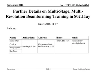
April 2017 doc.: IEEE 802.11-17/0595r0 Channel Estimation Field for EDMG OFDM PHY in 11ay Date: 2017-04-14 Authors: Name Affiliations Address Phone email +7 (831) 2969444 Turgeneva 30, Nizhny Novgorod, 603024, Russia artyom.lomayev@intel.com Artyom Lomayev Intel alexander.maltsev@intel.com Alexander Maltsev Intel miki.genossar@intel.com Miki Genossar Intel claudio.da.silva@intel.com Claudio da Silva Intel carlos.cordeiro@intel.com Carlos Cordeiro Intel Submission Slide 1 Intel Corporation
April 2017 doc.: IEEE 802.11-17/0595r0 Introduction This presentation proposes a design of the Channel Estimation Field (CEF) for EDMG OFDM PHY for PPDU transmission over a 2.16 GHz channel in 11ay. Submission Slide 2 Intel Corporation
April 2017 doc.: IEEE 802.11-17/0595r0 Legacy DMG-CEF for OFDM PHY Legacy 11ad DMG-CEF, [1]: The legacy DMG-CEF field for OFDM PHY is defined in time domain and is based on the Golay sequences similar to the SC PHY; The pulse shaping filter impulse response is defined in the standard, it has almost flat frequency response for in-band subcarriers corresponding to the data and pilots; The maximum frequency response amplitude deviation for the data subcarriers is equal to ~0.8 dB; Figures below show pulse shaping filter time and frequency responses; Submission Slide 3 Intel Corporation
April 2017 doc.: IEEE 802.11-17/0595r0 EDMG-CEF Definition, NCB = 1 In accordance with [2], the EDMG-CEF for 2.16 GHz (NCB = 1) PPDU transmission is defined in frequency domain as follows: EDMG-CEFiSTS-177, 177 = [SeqiSTSleft, 176, 0, 0, 0, SeqiSTSright, 176], iSTS =1, 2, 3, 4, 5, 6, 7, 8 Pilot sequences: SeqiSTSleft,176 and SeqiSTSright,176 are well designed pilot sequences providing low PAPR in time domain after application of IDFT; Each space-time stream iSTS has its own sequence {SeqiSTSleft,176, SeqiSTSright,176}, composing a sequence set; Submission Slide 4 Intel Corporation
April 2017 doc.: IEEE 802.11-17/0595r0 EDMG-CEF Definition, NCB > 1 There are two main approaches to design EDMG-CEF for NCB > 1: Independent sequence design for each NCB factor: 4.32 GHz, NCB = 2: EDMG-CEFiSTS-386, 386 = [SeqiSTSleft, 385, 0, 0, 0, SeqiSTSright, 385] 6.48 GHz, NCB = 3: EDMG-CEFiSTS-596, 596 = [SeqiSTSleft, 595, 0, 0, 0, SeqiSTSright, 595] 8.64 GHz, NCB = 4: EDMG-CEFiSTS-805, 805 = [SeqiSTSleft, 804, 0, 0, 0, SeqiSTSright, 804] iSTS =1, 2, 3, 4, 5, 6, 7, 8 Modular design based on the EDMG-CEF for NCB = 1, [1]: EDMG-CEFiSTS-386, 386 = [SeqiSTSleft, 3P, SeqiSTSright, 30P, 0, 0, 0, 30P, SeqiSTSleft, 3P, SeqiSTSright]; EDMG-CEFiSTS-596, 596 = [SeqiSTSleft, 3P, SeqiSTSright, 64P, SeqiSTSleft, 0, 0, 0, SeqiSTSright, 64P, SeqiSTSleft, 3P, SeqiSTSright]; EDMG-CEFiSTS-805, 805 = [SeqiSTSleft, 3P, SeqiSTSright, 64P, SeqiSTSleft, 3P, SeqiSTSright, 30P, 0, 0, 0, SeqiSTSleft, 3P, SeqiSTSright, 64P, SeqiSTSleft, 3P, SeqiSTSright, ]; 3P, 30P, and 64P notation defines 3, 30, and 64 pilots accordingly; Submission Slide 5 Intel Corporation
April 2017 doc.: IEEE 802.11-17/0595r0 Sequence Set Design for NCB =1 Design rules: A frequency domain pilot sequence {SeqiSTSleft,176, SeqiSTSright,176}, for the iSTS-th space-time stream, iSTS = 1:NSTS, is defined using { 1, j} alphabet; Comment: this allows simple channel estimation avoiding implementation of division operation; The Peak to Average Power Ratio (PAPR) for each sequence {SeqiSTSleft,176, SeqiSTSright,176} in the set should be less or equal to 3.0 dB; Comment: low PAPR value allows channel estimation in the linear power amplifier regime, this minimizes the non-linear distortion of the resulting channel estimation; All frequency domain pilot sequences {SeqiSTSleft,176, SeqiSTSright,176}, iSTS = 1:NSTS, should be different; Comment: this allows to avoid unintentional beamforming; Submission Slide 6 Intel Corporation
April 2017 doc.: IEEE 802.11-17/0595r0 Sequence Set Construction The sequence set {SeqiSTSleft,176, SeqiSTSright,176}, iSTS = 1:NSTS for MIMO is constructed applying iterative procedure described below. { 1, j} alphabet: AiSTS0 = {+1, +j, +j, -1, -j, +j, -1, +1, -1, +j, +1}, iSTS = 1, 2, , 8; BiSTS0 = {-1, +1, -1, +j, +1, +1, -j, -j, -j, +1, +1} , iSTS = 1, 2, , 8; The iterative procedure for the i-th sequence is defined as follows: AiSTSk = {WiSTSk *AiSTSk-1, BiSTSk-1}; BiSTSk = {WiSTSk *AiSTSk-1, -BiSTSk-1}; where k defines iteration index; To achieve the sequence length for A and B of 176 symbols, one needs to make 4 iterations, i.e. k = 1, 2, , 4, this gives 176 = 16 * 11; The sequences SeqiSTSleft,176, SeqiSTSright,176 are defined as follows: SeqiSTSleft,176 = BiSTS4, SeqiSTSright,176 = AiSTS4; The iteration process starts from the basic sequences AiSTS0 and BiSTS0 defined using Submission Slide 7 Intel Corporation
April 2017 doc.: IEEE 802.11-17/0595r0 Weight Vector Definition Table 1: Weight vector definition. WiSTSk vector Space-time stream # 1 2 3 4 5 6 7 8 [+1,-1,+j,-j] [-j,+1,-j,-j] [+1,-j,+1,-j] [-1,+1,-1,-j] [+1,+j,-1,-j] [-1,+j,+1,-j] [+j,-j,-j,-j] [+1,+1,+j,-j] Submission Slide 8 Intel Corporation
April 2017 doc.: IEEE 802.11-17/0595r0 Sequence Set PAPR Properties Table 2 below provides a summary of PTPR properties of the designed sequence set. Table 2: Peak to average power ratio in [dB] for EDMG-CEF signal in time domain. Space-time stream # 1 2 3 4 5 6 7 8 W vector PAPR, [dB], NCB = 1 2.9775 [+1,-1,+j,-j] 2.9788 [-j,+1,-j,-j] 2.9800 [+1,-j,+1,-j] 2.9800 [-1,+1,-1,-j] 2.9838 [+1,+j,-1,-j] 2.9845 [-1,+j,+1,-j] 2.9886 [+j,-j,-j,-j] 2.9923 [+1,+1,+j,-j] Submission Slide 9 Intel Corporation
April 2017 doc.: IEEE 802.11-17/0595r0 PAPR Properties of DMG-CEF for OFDM DMG-CEF PAPR properties: The DMG-CEF field is defined using Gv512 and Gu512 sequences in time domain: Gv512= {-Gb128, +Ga128, -Gb128, -Ga128}; Gu512= {-Gb128, -Ga128, +Gb128, -Ga128}; Cef = {-Ga128, +Gv512, +Gu512, -Gb128}; The original CEF filed is defined at the SC chip rate 1.76 GHz, then it is resampled to the OFDM sample rate 1.5 x 1.76 = 2.64 GHz applying x3 times up sampling, filtering, and x2 times down sampling procedure; Filter characteristics are defined in the 11ad std. and shown at the previous slide; Estimated PAPR: The estimated PAPR for DMG-CEF: 3.1292 dB; Conclusion: The proposed EDMG-CEF sequence set has acceptable PAPR properties; Submission Slide 10 Intel Corporation
April 2017 doc.: IEEE 802.11-17/0595r0 PAPR Properties of VHT-CEF for OFDM The IEEE 802.11ac standard defines sequence for VHT-LTF field used for channel estimation with PAPR properties summarized in Table 3, [1]. Table 3: Peak to average power ratio in [dB] for VHT-CEF signal in time domain. Space-time stream # NCB = 1 NCB = 2 NCB = 3 NCB = 4 1 - 8 3.5766 3.4066 N/A 4.7514 Conclusion: Proposed sequences have slightly better PAPR properties than defined in 11ac standard. Submission Slide 11 Intel Corporation
April 2017 doc.: IEEE 802.11-17/0595r0 Transmit Waveform Definition The EDMG-CEF field transmit waveform in time domain is defined as follows: ( ) ( ) 1 , = n TX i EDMG r qT w qT CEF s s Tone EDMG N N STS CEF Q N N ( ( ) ) 1 , SR STS i N EDMG exp 2 EDMG P EDMG CEF j k qT T n N STS STS k CEF k F s GI long CEF , , TX i i i n STS STS = = 1 k N i SR STS PEDMG-CEF is the EDMG-CEF mapping matrix; Qk is spatial mapping matrix per k-th subcarrier; is the total number of active subcarrier; is the number of OFDM symbols in EDMG CEF for given total number of space-time streams NSTS; = Tone EDMG N EDMG N N N CEF ST DC N STS CEF Submission Slide 12 Intel Corporation
April 2017 doc.: IEEE 802.11-17/0595r0 EDMG-CEF Mapping Matrix EDMG-CEF mapping matrix: = + , 1 = N EDMG 1 2 EDMG P N STS CEF CEF + 1 1 + + + 1 1 1 1 = = N EDMG , 2 EDMG P N STS CEF CEF + + 1 1 + + + 1 1 1 1 = = = N EDMG , 4 EDMG P P N STS 4 4 CEF x CEF + + + 1 1 1 1 + + w 1 1 w 1 + + + 1 1 1 1 ( ) = + = = N EDMG 1 3 2 3 1 , exp 2 / 3 , 3 EDMG P w j N STS 3 CEF CEF + 2 3 4 3 1 w w + + w + w + w 1 1 1 1 1 1 + 1 6 2 6 3 6 4 6 5 6 1 w w P P + 2 6 4 6 6 6 8 6 10 6 1 w w w w w = = N EDMG ( ) 4 4 4 P 4 x x , 8 EDMG P N STS = = = N EDMG , exp 2 / 6 , 6 EDMG P w j N STS CEF CEF P 6 CEF CEF + 3 6 6 6 9 6 12 6 15 6 1 w w w w w 4 4 4 4 x x + 4 6 8 6 12 6 16 6 20 6 1 w w w w w + 5 6 10 6 15 6 20 6 25 6 1 w w w w w Submission Slide 13 Intel Corporation
April 2017 doc.: IEEE 802.11-17/0595r0 Simulation Results Channel estimation in frequency domain: Estimation time interval 2 OFDM symbols; Solid line perfect channel knowledge, dashed line channel estimation; LOS channel, flat NLOS channel, Rayleigh, RMS = 3 ns LOS channel: min SNR degradation ~0.2 dB, max SNR degradation ~0.4 dB NLOS channel: min SNR degradation ~0.5 dB, max SNR degradation ~0.9 dB Submission Slide 14 Intel Corporation
April 2017 doc.: IEEE 802.11-17/0595r0 Notes on EDMG-CEF Design, NCB > 1 Intel completed analysis and design of EDMG-CEF for NCB > 1 applying independent sequence design for each NCB. The summary of achieved PAPR sequence characteristics are defined in the Table 4 below. Table 4: Peak to average power ratio in [dB] for EDMG-CEF signal in time domain. Space-time stream # NCB = 1 NCB = 2 NCB = 3 NCB = 4 1 2 3 4 5 6 7 8 2.9775 2.9788 2.9800 2.9800 2.9838 2.9845 2.9886 2.9923 3.2192 3.2259 3.2261 3.2270 3.2292 3.2299 3.2477 3.2499 3.5595 3.5654 3.5895 3.6065 3.6201 3.6208 3.6314 3.6395 3.2681 3.2696 3.2928 3.3038 3.3066 3.3114 3.3188 3.3190 Submission Slide 15 Intel Corporation
April 2017 doc.: IEEE 802.11-17/0595r0 Conclusions This presentation proposes design of EDMG-CEF field for PPDU transmission over a 2.16 GHz channel. The sequence design is based on the regular iterative procedure. The proposed sequence set has low PAPR (less than 3.0 dB) with almost constant PAPR value over the set. Submission Slide 16 Intel Corporation
April 2017 doc.: IEEE 802.11-17/0595r0 SP/M Do you agree: to include the text from (11-17-0596-00-00ay 30 6 3 OFDM EDMG-CEF Definition) defining EDMG-CEF field for PPDU transmission over the 2.16 GHz channel to the spec draft? Submission Slide 17 Intel Corporation
April 2017 doc.: IEEE 802.11-17/0595r0 References 1. IEEE802.11-2016 2. 11-17-0594-00-00ay Definition in 11ay 3. Draft P802.11ay_D0.3 OFDM Signal Parameters Submission Slide 18 Intel Corporation