Network Slicing in 5GC
Network slicing in 5G Core (5GC) enables the creation of multiple virtual networks on a single physical infrastructure to cater to diverse requirements. The Non-Roaming 5G System Architecture outlines the reference points and functions involved in a 5G system. Service-Based Architecture (SBA) and Network Slice Selection Function play key roles in ensuring efficient network operations. Network Slice Selection Assistance Information (NSSAI) defines sets of S-NSSAIs and configurations related to network slice selection. PLMN Introduction provides insights into Public Land Mobile Networks and their components like MCC and MNC. The concept of Single Network Slice Selection Assistance Information (S-NSSAI) further delves into identifying and using network slices based on specific criteria.

Download Presentation

Please find below an Image/Link to download the presentation.
The content on the website is provided AS IS for your information and personal use only. It may not be sold, licensed, or shared on other websites without obtaining consent from the author.If you encounter any issues during the download, it is possible that the publisher has removed the file from their server.
You are allowed to download the files provided on this website for personal or commercial use, subject to the condition that they are used lawfully. All files are the property of their respective owners.
The content on the website is provided AS IS for your information and personal use only. It may not be sold, licensed, or shared on other websites without obtaining consent from the author.
E N D
Presentation Transcript
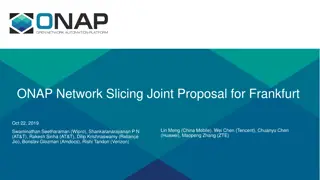
Non-Roaming 5G System Architecture Reference Point Representation N13 NSSF AUSF UDM N12 N8 N10 N22 N5 N11 N7 AMF SMF PCF AF N1 N15 N14 N2 N4 UE (R)AN UPF DN N3 N6 N9 Authentication Server Function (AUSF) Access and Mobility Management Function (AMF) Data Network (DN) Network Slice Selection Function (NSSF) Policy Control Function (PCF) Session Management Function (SMF) Unified Data Management (UDM) Unified Data Repository (UDR) User Plane Function (UPF) Application Function (AF) User Equipment (UE) (Radio) Access Network ((R)AN)
Service-Based Architecture (SBA) Network Slice Selection Function
Network Slice Selection Assistance Information (NSSAI) A set of one or more S-NSSAIs is called the NSSAI Default Configured NSSAI Default NSSAI setting by HPLMN 7 6 5 4 3 2 1 0 Configured NSSAI Configure by current PLMN With PLMN identity Stored in the UE is a set composed of at most 16 S-NSSAIs 0 NSSAI IEI 1 Length of NSSAI contents 2~n List of S-NSSAI 1 Requested NSSAI NSSAI provided by the UE to the Serving PLMN during registration Allowed NSSAI NSSAI provided by the Serving PLMN during registration A Registration procedure, indicating the S-NSSAIs values the UE could use in the Serving PLMN for the current registration area Stored in the UE is a set composed of at most 8 S-NSSAIs Rejected NSSAI NSSAI rejected by the Serving PLMN during registration With PLMN identity
PLMN Introduction IMSI stored in UE SIM card Include MCC and MNC PLMN MCC + MNC HPLMN PLMN same as UE MCC and MNC VPLMN UE visited PLMN with difference MCC and MNC from UE MCC : Mobile Country Code MNC : Mobile Network Code PLMN : Public Land Mobile Network HPLMN : Home PLMN VPLMN : Visited PLMN UE IMSI MCC = 466 MNC = 11 VPLMN HPLMN PLMN = 46000 PLMN = 46611
Single Network Slice Selection Assistance Information (S-NSSAI) 7 6 5 4 3 2 1 0 0 S-NSSAI IEI Identifies a Network Slice 1 Length of S-NSSAIcontents Subscribed S-NSSAIs S-NSSAI based on subscriber information, which a UE is subscribed to use in a PLMN 2 SST 3 SD 5 Mapped S-NSSAI In roaming scenarios, a mapping S-NSSAI values between HPLMN and Serving PLMN 6 Mapped configured SST 7 Mapped configured SD A Slice/Service type (SST) The expected Network Slice behavior in terms of features and services 9 A Slice Differentiator (SD) Optional information that complements the Slice/Service type(s) to differentiate amongst multiple Network Slices of the same Slice/Service type Network may at any one time serve the UE with only one Network Slice instance associated with this S-NSSAI
S-NSSAI values Slice/Service type SST value Characteristics. eMBB 1 Slice suitable for the handling of 5G enhanced Mobile Broadband. Slice suitable for the handling of ultra- reliable low latency communications. URLLC 2 MIoT 3 Slice suitable for the handling of massive IoT. Standard SST Value Structure of S-NSSAI
(DN)(User Plane) 1 Registration Management(RM) AMF 2 PDU Session Service-Based Architecture (SBA)
Network Slice Registration UE gNB AMF AUSF UDM NSSF 1. Registration Request 2. AMF Selection 3. Registration Request 4a. Subscriber Data Request 4b. Subscriber Data Response 5a. Network Slice Selection Request 5b. Network Slice Selection Response 6. AMF Re-allocation 7. Authentication / Security 8. Registration Accept
Network Slice Registration (Step 1) UE gNB AMF AUSF UDM NSSF 1. Registration Request RRCSetupComplete Registration Request Requested NSSAI 2. AMF Selection 3. Registration Request Requested NSSAI If UE has Configured NSSAI and/or Allowed NSSAI for the current PLMN Select S-NSSAI from Configured NSSAI and Allowed NSSAI If UE has neither Allowed NSSAI nor Configured NSSAI for the current PLMN and has Default Configured NSSAI Select S-NSSAI from Default Configured NSSAI and Allowed NSSAI Otherwise No S-NSSAI 4a. Subscriber Data Request 4b. Subscriber Data Response 5a. Network Slice Selection Request 5b. Network Slice Selection Response 6. AMF Re-allocation Roaming scenarios UE shall also provide the Mapped S-NSSAI(s) for the requested NSSAI, if available 7. Authentication / Security 8. Registration Accept
Network Slice Registration (Step 2) UE gNB AMF AUSF UDM NSSF 1. Registration Request 2. AMF Selection 3. Registration Request gNB select AMF base on Requested NSSAI If RAN cannot make a choice or no Requested NSSAI Send to default AMF 4a. Subscriber Data Request 4b. Subscriber Data Response 5a. Network Slice Selection Request 5b. Network Slice Selection Response 6. AMF Re-allocation 7. Authentication / Security 8. Registration Accept
Network Slice Registration (Step 3) UE gNB AMF AUSF UDM NSSF 1. Registration Request 2. AMF Selection 3. Registration Request 4a. Subscriber Data Request Initial UE Message Registration Request 4b. Subscriber Data Response Initial UE Message include Registration Request same as Step 1 gNB sends the Initial UE Message to the AMF selected in step 2 5a. Network Slice Selection Request 5b. Network Slice Selection Response 6. AMF Re-allocation 7. Authentication / Security 8. Registration Accept
Network Slice Registration (Step 4) UE gNB AMF AUSF UDM NSSF 1. Registration Request 2. AMF Selection 3. Registration Request UDM Services Nudm_SDM_Get Inputs AMF ID, Slice Selection Subscription data , SUPI Outputs Subscribed S-NSSAI(s) 4a. Subscriber Data Request Type Key 4b. Subscriber Data Response 5a. Network Slice Selection Request 5b. Network Slice Selection Response Conditions The initial AMF needs UE's subscription information to decide whether to reroute the Registration Request UE's slice selection subscription information was not provided by old AMF 6. AMF Re-allocation 7. Authentication / Security Actions Get the Network Slices that the UE subscribes to 8. Registration Accept In roaming case, it indicates the subscribed network slices applicable to the serving PLMN
Network Slice Registration (Step 5) UE gNB AMF AUSF UDM NSSF 1. Registration Request 2. AMF Selection NSSF Services Nnssf_NSSelection_Get Inputs Requested NSSAI Roaming : [Mapping Of Requested NSSAI] Subscribed S-NSSAI(s) With default S-NSSAI indication TAI (tracking area identity ) of UE Allowed NSSAI for the other access type (if any) Roaming : [Mapping of Allowed NSSAI] PLMN ID of the SUPI 3. Registration Request 4a. Subscriber Data Request 4b. Subscriber Data Response 5a. Network Slice Selection Request 5b. Network Slice Selection Response Outputs AMF Set or list of AMF addresses, Allowed NSSAI per access type (may be more than one allowed NSSAI) Roaming : [Mapping Of Allowed NSSAI] [NSI ID(s)], [NRF(s)], [List of rejected (S-NSSAI(s), cause value(s))], [Configured NSSAI for the Serving PLMN] Conditions AMF cannot serve all the S-NSSAI(s) from the Requested NSSAI permitted by the subscription information Actions NSSF provide the relevant Network Slice information to AMF 6. AMF Re-allocation 7. Authentication / Security 8. Registration Accept Roaming : [ Mapping Of Configured NSSAI]
Network Slice Registration (Step 6) UE gNB AMF AUSF UDM NSSF 1. Registration Request 2. AMF Selection 3. Registration Request 4a. Subscriber Data Request 4b. Subscriber Data Response 5a. Network Slice Selection Request 5b. Network Slice Selection Response 6. AMF Re-allocation 7. Authentication / Security AMF select a target AMF and executes the re-allocation process 8. Registration Accept
Network Slice Registration (Step 7) UE gNB AMF AUSF UDM NSSF 1. Registration Request 2. AMF Selection 3. Registration Request 4a. Subscriber Data Request 4b. Subscriber Data Response 5a. Network Slice Selection Request AMF send authentication request to AUSF AUSF selects a UDM and gets the authentication data from UDM If NAS security context does not exist, the NAS security initiation is performed gNB stores the security context and acknowledges to the AMF gNB uses the security context to protect the messages exchanged with the UE 5b. Network Slice Selection Response 6. AMF Re-allocation 7. Authentication / Security 8. Registration Accept
Network Slice Registration (Step 8) UE gNB AMF AUSF UDM NSSF 1. Registration Request 2. AMF Selection 3. Registration Request 4a. Subscriber Data Request AMF -> gNB Initial Context Setup Request Registration Accept Old AMF (If gNB does not participate in AMF Re-allocation ) 4b. Subscriber Data Response 5a. Network Slice Selection Request gNB -> UE RRCReconfigurationComplete Registration Accept 5b. Network Slice Selection Response 6. AMF Re-allocation Registration Accept PDU Session status Allowed NSSAI Roaming : [Mapping Of Allowed NSSAI] [Configured NSSAI for the Serving PLMN] Roaming : [Mapping Of Configured NSSAI] [rejected S-NSSAIs] 7. Authentication / Security 8. Registration Accept
Network Slice Registration UE gNB AMF AUSF UDM NSSF 1. Registration Request 2. AMF Selection 3. Registration Request 4a. Subscriber Data Request 4b. Subscriber Data Response 5a. Network Slice Selection Request 5b. Network Slice Selection Response 6. AMF Re-allocation 7. Authentication / Security 8. Registration Accept
AMF Re-allocation UE have 3 Network Slice (S-NSSAI) Find a AMF to service Network Slice 1,2,and 3 Network Slice 1 Network Slice 2 AMF A AMF B Network Slice 3 Initial AMF AMF C Select AMF C as Target AMF to service all Network Slice Re-allocate initial AMF to AMF C
AMF Re-allocation - Step 6 at Registration Initial AMF Target AMF gNB NRF 6a. AMF Discovery Request 6b. AMF Discovery Response 6c. Registration Request (A) 6d.Reroute NAS message (B) 6e. Registration Request
AMF Re-allocation - Step 6 at Registration (Step a,b) Initial AMF Target AMF gNB NRF 6a. AMF Discovery Request 6b. AMF Discovery Response NRF Services Nnrf_NFDiscovery Inputs NF type=AMF AMF Set Outputs list of ( ) 6c. Registration Request (A) 6d.Reroute NAS message (B) 6e. Registration Request AMF pointer, AMF address plus additional selection rules and NF capabilities Conditions If initial AMF does not locally store the target AMF address that use at AMF Re-allocation Actions Get the AMF information
AMF Re-allocation - Step 6 at Registration (Step c) Initial AMF Target AMF gNB NRF 6a. AMF Discovery Request 6b. AMF Discovery Response 6c. Registration Request (A) 6d.Reroute NAS message If the initial AMF, based on local policy and subscription information, decides to forward the NAS message to the target AMF directly (B) 6e. Registration Request AMF Services Namf_Communication_N1MessageNotify Inputs Initial AMF ID SUPI N2 terminating point Registration Request information from the NSSF
AMF Re-allocation - Step 6 at Registration (Step d,e) Initial AMF Target AMF gNB NRF 6a. AMF Discovery Request 6b. AMF Discovery Response 6c. Registration Request (A) If the initial AMF, based on local policy and subscription information, decides to forward the NAS message to the target AMF via (R)AN 6d.Reroute NAS message (B) 6e. Registration Request 6d. Reroute NAS message Information about the target AMF Information about the Registration Request message Information from the NSSF 6e. Initial UE Message Registration Request
Network Slice Registration (Step 8) UE gNB AMF AUSF UDM NSSF 1. Registration Request 2. AMF Selection 3. Registration Request 4a. Subscriber Data Request AMF -> gNB Initial Context Setup Request Registration Accept Old AMF (If gNB does not participate in AMF Re-allocation ) 4b. Subscriber Data Response 5a. Network Slice Selection Request gNB -> UE RRCReconfigurationComplete Registration Accept 5b. Network Slice Selection Response 6. AMF Re-allocation Registration Accept PDU Session status Allowed NSSAI Roaming : [Mapping Of Allowed NSSAI] [Configured NSSAI for the Serving PLMN] Roaming : [Mapping Of Configured NSSAI] [rejected S-NSSAIs] 7. Authentication / Security 8. Registration Accept
(DN)(User Plane) 1 Registration Management(RM) AMF 2 PDU Session Service-Based Architecture (SBA)
PDU session (1) UE has 3 Allows S-NSSAI Network Slice 1 (S-NSSAI = 1) Network Slice 2 (S-NSSAI = 2) Network Slice 3 (S-NSSAI = 3) UE can only setup PDU session for Allows S-NSSAI DN UPF S-NSSAI = 1 PDU session ID : 10 S-NSSAI = 1 PDU session ID : 11 S-NSSAI = 3 PDU session ID : 12 S-NSSAI = 2 PDU session ID : 13 PDU session ID : 14 S-NSSAI = 1 S-NSSAI = 2 PDU session ID : 15 PDU session ID must be unique
PDU session (2) N3 N6 DN UPF (PSA) N3 N9 N6 DN I-UPF UPF (PSA) N3 N6 UPF UP CL DN UPF (PSA) 1 N3 N9 N4 N3 N4 N4 I-UPF SMF Uplink data classify by UP CL UPF and forward to difference DN N4 PSA : PDU session anchor I-UPF : Intermediate PDU UP CL : Uplink Classifier N9 N6 DN UPF (PSA) 2
PDU session establishment UPF UE gNB AMF SMF 1. PDU Session Establishment Request 2. SMF Selection 3. PDU Session Creation 4. UPF Selection 5. Session Establishment 6. PDU Session Message Transfer 7. PDU Session Request 8. Resource Setup 9. PDU Session Response 10. PDU Session Update Request 11. Session Update 12. PDU Session Update Response
PDU session establishment (Step 1) UPF UE gNB AMF SMF 1. PDU Session Establishment Request NAS Message S-NSSAI(s) DNN PDU Session ID Request type PDU Session Establishment PDU session ID Requested PDU Session Type IPv4 2. SMF Selection 3. PDU Session Creation Allowed NSSAI of the current access type Optionally 4. UPF Selection IPv6 IPv4v6 Ethernet Optionally 5. Session Establishment Unstructured Requested SSC mode Initial Request Existing PDU Session 6. PDU Session Message Transfer 7. PDU Session Request PDU Session Handover N1 SM container (PDU Session Establishment) 8. Resource Setup 9. PDU Session Response 10. PDU Session Update Request 11. Session Update 12. PDU Session Update Response
PDU session establishment(Step 2-1) UPF UE gNB AMF SMF 1. PDU Session Establishment Request 2. SMF Selection 3. PDU Session Creation Determines S-NSSAI If the NAS message does not contain an S-NSSAI Default S-NSSAI for the requested PDU Session either according to the UE subscription 4. UPF Selection 5. Session Establishment Determines DN If the NAS Message contains an S-NSSAI but it does not contain a DNN 6. PDU Session Message Transfer 7. PDU Session Request 8. Resource Setup Default DNN for this S-NSSAI if the default DNN is present in the UE's Subscription Information otherwise the serving AMF selects a locally configured DNN for this S-NSSAI 9. PDU Session Response 10. PDU Session Update Request 11. Session Update Determines SMF If the AMF cannot select an SMF Reject PDU Session Establishment Request 12. PDU Session Update Response
PDU session establishment(Step 2-2) UPF UE gNB AMF SMF 1. PDU Session Establishment Request 2. SMF Selection 3. PDU Session Creation NSSF Services Nnssf_NSSelection_Get Inputs S-NSSAI from the Allowed NSSAI requested by the UE PLMN ID of the SUPI TAI of the UE the indication that the request is within a procedure of PDU Session establishment Output NRF AMF NSSF NRF 4. UPF Selection 2a. Network Slice Selection Request 5. Session Establishment 2b. Network Slice Selection Response 6. PDU Session Message Transfer 7. PDU Session Request 2c. SMF Discovery Request 8. Resource Setup optionally may return a NSI ID 2d. SMF Discovery Response 9. PDU Session Response 10. PDU Session Update Request Conditions When the serving AMF is not aware of the appropriate NRF to be used to select NFs/services within the corresponding Network Slice instance Actions NSSF provide the NRF information to AMF 11. Session Update 12. PDU Session Update Response
PDU session establishment(Step 2-2) UPF UE gNB AMF SMF 1. PDU Session Establishment Request 2. SMF Selection 3. PDU Session Creation NRF Services Nnrf_NFDiscovery Inputs NF type=SMF S-NSSAI from the Allowed NSSAI PLMN ID of the SUPI DNN possibly NSI ID 4. UPF Selection AMF NSSF NRF 5. Session Establishment 2a. Network Slice Selection Request 6. PDU Session Message Transfer 2b. Network Slice Selection Response 7. PDU Session Request 8. Resource Setup Outputs FQDN or IP address of SMF Set of the discovered SMF instance(s) or Endpoint Address(es) of SMF service instance(s) Possibly an NSI ID 2c. SMF Discovery Request 9. PDU Session Response 2d. SMF Discovery Response 10. PDU Session Update Request 11. Session Update 12. PDU Session Update Response
PDU session establishment(Step 3) UPF UE gNB AMF SMF 1. PDU Session Establishment Request 2. SMF Selection 3. PDU Session Creation SMF Services Nsmf_PDUSession_CreateSMContext Request Type : initial request Nsmf_PDUSession_UpdateSMContext Request Type : existing PDU Session 4. UPF Selection 5. Session Establishment Nsmf_PDUSession_CreateSMContext 6. PDU Session Message Transfer Inputs SUPI, DNN, PDU Session ID, AMF ID, Request Type S-NSSAI(s) Allowed NSSAI N1 SM container (PDU Session Establishment Request) Outputs SM Context ID or N1 SM container (PDU Session Reject (Cause)) Nsmf_PDUSession_UpdateSMContext Inputs SUPI, DNN, PDU Session ID, AMF ID, Request Type S-NSSAI(s) 7. PDU Session Request 8. Resource Setup Allowed NSSAI N1 SM container (PDU Session Establishment Request) Outputs SM Context ID or N1 SM container (PDU Session Reject (Cause)) 9. PDU Session Response 10. PDU Session Update Request 11. Session Update 12. PDU Session Update Response
PDU session establishment(Step 4) UPF UE gNB AMF SMF 1. PDU Session Establishment Request PDU Session address Allocation IPv4 IPv6 build its link-local address IPv4v6 build its link-local address IPv6 prefix Unstructured PDU Session Type N6 point-to-point tunnelling based on UDP/IPv6 MAC 2. SMF Selection 3. PDU Session Creation 4. UPF Selection 5. Session Establishment 6. PDU Session Message Transfer 7. PDU Session Request Ethernet PDU Session SMF NSSF NRF 8. Resource Setup NRF Services 4a. Network Slice Selection Request 9. PDU Session Response Nnrf_NFDiscovery_Request Inputs NF type=UPF DNN S-NSSAI SMF Area Identity Outputs FQDN or IP address of UPF 10. PDU Session Update Request 4b. Network Slice Selection Response 11. Session Update 4c. UPF Discovery Request 12. PDU Session Update Response 4d. UPF Discovery Response
PDU session establishment(Step 5) UPF UE gNB AMF SMF 1. PDU Session Establishment Request 2. SMF Selection 3. PDU Session Creation 4. UPF Selection 5. Session Establishment 6. PDU Session Message Transfer N4 Session Establishment Request Type : initial request N4 Session Modification Otherwise N4 Session Establishment/Modification Request Packet detection Enforcement 7. PDU Session Request 8. Resource Setup reporting rules CN Tunnel CN Tunnel Info is allocated by the SMF Inactivity Timer If the selective User Plane deactivation is required Conditions If the Request Type indicates "Existing PDU Session", and the SMF creates CN Tunnel Info, then this step is skipped Actions SMF initiate N4 Session Establishment/Modification procedure with each UPF of the PDU Session 9. PDU Session Response 10. PDU Session Update Request 11. Session Update N4 Session Establishment/Modification Response CN Tunnel CN Tunnel Info is allocated by the UPF 12. PDU Session Update Response
PDU session establishment(Step 6) UPF UE gNB AMF SMF 1. PDU Session Establishment Request 2. SMF Selection 3. PDU Session Creation 4. UPF Selection 5. Session Establishment 6. PDU Session Message Transfer AMF Services Namf_Communication_N1N2MessageTransfer 7. PDU Session Request 8. Resource Setup Inputs PDU Session ID N1 SM container (PDU Session Establishment Accept (QoS Rule(s), S-NSSAI(s), DNN, IP Address, , Session-AMBR) N2 SM information (PDU Session ID, QFI(s), QoS Profile(s), CN Tunnel Info, Session-AMBR, PDU Session Type) 9. PDU Session Response 10. PDU Session Update Request 11. Session Update 12. PDU Session Update Response
PDU session establishment(Step 7) UPF UE gNB AMF SMF 1. PDU Session Establishment Request 2. SMF Selection 3. PDU Session Creation 4. UPF Selection 5. Session Establishment 6. PDU Session Message Transfer 7. PDU Session Request 8. Resource Setup N2 PDU Session Request N2 SM information NAS message PDU Session ID, N1 SM container (PDU Session Establishment Accept) 9. PDU Session Response 10. PDU Session Update Request 11. Session Update 12. PDU Session Update Response
PDU session establishment(Step 8) UPF UE gNB AMF SMF 1. PDU Session Establishment Request 2. SMF Selection 3. PDU Session Creation 4. UPF Selection 5. Session Establishment 6. PDU Session Message Transfer 7. PDU Session Request 8. Resource Setup 9. PDU Session Response Setup gNB for PDU session gNB allocates (R)AN N3 Tunnel Info for the PDU Session QFI setting gNB Send RRC Connection Reconfiguration to UE RAN Forwards the NAS message to UE PDU Session ID N1 SM container (PDU Session Establishment Accept) 10. PDU Session Update Request 11. Session Update 12. PDU Session Update Response
PDU session establishment(Step 9) UPF UE gNB AMF SMF 1. PDU Session Establishment Request 2. SMF Selection 3. PDU Session Creation 4. UPF Selection 5. Session Establishment 6. PDU Session Message Transfer 7. PDU Session Request 8. Resource Setup After this step, uplink channel is sucess. UE can be start to sent Uplink Data 9. PDU Session Response 10. PDU Session Update Request 11. Session Update N2 PDU Session Response PDU Session ID Cause N2 SM information (PDU Session ID, AN Tunnel Info, List of accepted/rejected QFI(s), User Plane Enforcement Policy Notification) 12. PDU Session Update Response
PDU session establishment(Step 10) UPF UE gNB AMF SMF 1. PDU Session Establishment Request 2. SMF Selection 3. PDU Session Creation 4. UPF Selection 5. Session Establishment 6. PDU Session Message Transfer 7. PDU Session Request 8. Resource Setup 9. PDU Session Response 10. PDU Session Update Request SMF Services Nsmf_PDUSession_UpdateSMContext Request Inputs N2 SM information Request Type 11. Session Update If the list of rejected QFI(s) is included in N2 SM information, 12. PDU Session Update Response the SMF shall release the rejected QFI(s)
PDU session establishment(Step 11) UPF UE gNB AMF SMF 1. PDU Session Establishment Request 2. SMF Selection 3. PDU Session Creation 4. UPF Selection 5. Session Establishment 6. PDU Session Message Transfer 7. PDU Session Request 8. Resource Setup 9. PDU Session Response 10. PDU Session Update Request N4 Session Modification Request AN Tunnel Info N4 Session Modification Response 11. Session Update 12. PDU Session Update Response After this step, the UPF delivers any down-link packets to the UE that may have been buffered for this PDU Session.
PDU session establishment(Step 12) UPF UE gNB AMF SMF 1. PDU Session Establishment Request 2. SMF Selection 3. PDU Session Creation 4. UPF Selection 5. Session Establishment 6. PDU Session Message Transfer 7. PDU Session Request 8. Resource Setup 9. PDU Session Response 10. PDU Session Update Request SMF Services Nsmf_PDUSession_UpdateSMContext Response 11. Session Update Outputs Cause 12. PDU Session Update Response
UE select the slice of the requirement 3GPP SA2 #121
Reference - Network Slicing -3GPP Network Slicing Standard TS 23.501 System architecture for the 5G System (5GS) TS 23.502 Procedures for the 5G System (5GS) TS 29.244 Interface between the Control Plane and the User Plane nodes TS 38.300 NR; Overall description; Stage-2 3GPP SA2_121


")
")


")
的用戶面(User")

")
")
")
")
")
")
")
")


")
")
")
")
的用戶面(User")
")
")

")
")
")
")
")
")
")
")
")
")
")
")
")
")