Module Flex Status & Tooling Discussion
The discussion revolves around the different types of flex modules, current powering constraints, surfaces, materials, and processes involved. There are plans for CAD drawings, tooling development, and meetings with various companies. The timeline for production is outlined, with a focus on stave flex production and component mounting.

Download Presentation

Please find below an Image/Link to download the presentation.
The content on the website is provided AS IS for your information and personal use only. It may not be sold, licensed, or shared on other websites without obtaining consent from the author.If you encounter any issues during the download, it is possible that the publisher has removed the file from their server.
You are allowed to download the files provided on this website for personal or commercial use, subject to the condition that they are used lawfully. All files are the property of their respective owners.
The content on the website is provided AS IS for your information and personal use only. It may not be sold, licensed, or shared on other websites without obtaining consent from the author.
E N D
Presentation Transcript
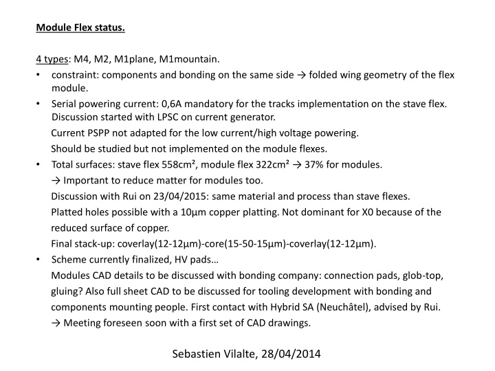
Module Flex status. 4 types: M4, M2, M1plane, M1mountain. constraint: components and bonding on the same side folded wing geometry of the flex module. Serial powering current: 0,6A mandatory for the tracks implementation on the stave flex. Discussion started with LPSC on current generator. Current PSPP not adapted for the low current/high voltage powering. Should be studied but not implemented on the module flexes. Total surfaces: stave flex 558cm , module flex 322cm 37% for modules. Important to reduce matter for modules too. Discussion with Rui on 23/04/2015: same material and process than stave flexes. Platted holes possible with a 10 m copper platting. Not dominant for X0 because of the reduced surface of copper. Final stack-up: coverlay(12-12 m)-core(15-50-15 m)-coverlay(12-12 m). Scheme currently finalized, HV pads Modules CAD details to be discussed with bonding company: connection pads, glob-top, gluing? Also full sheet CAD to be discussed for tooling development with bonding and components mounting people. First contact with Hybrid SA (Neuch tel), advised by Rui. Meeting foreseen soon with a first set of CAD drawings. Sebastien Vilalte, 28/04/2014
Tooling(s): to be discussed with Hybrid SA and LAPP for specific features: bending/folding Also with components mounting company. What are we going to do in LAPP? Compromise between time and money (gluing). Steps: Finish 1st version of CAD & meet Hybrid SA: end of May. Discuss with component mounting people (CERN, Addax?, not so trivial ). Rework of the CAD, tuning with Rui, launch prod: beginning of June. Can expect naked flexes for September. Components mounting: September. Gluing, bonding: sept,oct... Production: for one stave, total of 7 M4, 2 M1 and 13 M2. For electrical and mechanical tests, need at least 20 M4, 10 M1 and 40M2. Represents about 900cm , the equivalent surface of the stave flex prod. about 8000CHF. mounting, gluing, bonding: ??? connectors: 500 Linked developments: translation boards for module testing with USB-pix: 200 . TOTAL: 15-20k . Sebastien Vilalte, 28/04/2014