Microprocessor Output Devices and Memory Interfacing
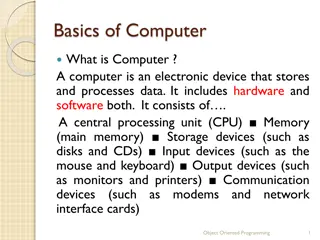
Selecting an output device helps in getting information from the processor, like using the OUT instruction where the processor places the data on the data bus. Interfacing a microprocessor involves connecting it to various components like main memory, graphic subsystem, and I/O devices. Memory interfacing aids the microprocessor in reading and writing data to memory, whereas I/O interfacing involves connecting devices like keyboards and displays. Accessing memory involves selecting the right memory chip, identifying locations, and accessing data. Memory in a microprocessor system holds data and instructions, categorized into main memory (RAM and ROM) and storage memory (disks, CD-ROMs, etc.).

Download Presentation

Please find below an Image/Link to download the presentation.
The content on the website is provided AS IS for your information and personal use only. It may not be sold, licensed, or shared on other websites without obtaining consent from the author.If you encounter any issues during the download, it is possible that the publisher has removed the file from their server.
You are allowed to download the files provided on this website for personal or commercial use, subject to the condition that they are used lawfully. All files are the property of their respective owners.
The content on the website is provided AS IS for your information and personal use only. It may not be sold, licensed, or shared on other websites without obtaining consent from the author.
E N D
Presentation Transcript
Device Selection and Data Transfer The objective of selecting an output device is to get information or a result out of the processor and store it or display it. The OUT instruction serves that purpose. During the execution of this instruction, the processor places that information (accumulator contents) on the data bus.
Interfacing of microprocessor A microprocessor would not be of much use by itself. To perform useful work it needs to be connected to other electronic components. For example, for a computer to work, a microprocessor must be interfaced to main memory, a graphic subsystem, disk memory, the keyboard and USB ports, etc. There are two types of interfacing: 1.Memory interfacing. 2. I/O interfacing.
Interfacing of microprocessor Memory interfacing: While executing an instruction, there is a necessity for the microprocessor to access memory frequently for reading various instruction codes and data stored in the memory. The primary function of a memory interfacing circuit is to aid the microprocessor in reading and writing a data to the given register of a memory chip.
Interfacing of microprocessor I/O Interfacing: We know that keyboard and Displays are used as communication channel with outside world. So it is necessary that we interface keyboard and displays with the microprocessor. This is called I/O interfacing.
Memory interfacing There needs to be a lot of interaction between the microprocessor and the memory for the exchange of information during program execution. 1. Memory has its requirements on control signals and their timing. 2. The microprocessor has its requirements as well. The interfacing operation is simply the matching of these requirements.
Memory interfacing Accessing memory can be summarized into the following three steps: 1. Select the right memory chip (using part of the address bus). 2. Identify the memory location (using the rest of the address bus). 3. Access the data (using the data bus).
The Design and Operation of Memory Memory in a microprocessor system is where information (data and instructions) is kept. It can be classified into two main types: Main memory (RAM and ROM) Storage memory (Disks , CD ROMs, etc.) The simple view of RAM is that it is made up of registers that are made up of flip-flops (or memory elements). The number of flip-flops in a memory register determines the size of the memory word. ROM on the other hand uses diodes instead of the flip- flops to permanently hold the information. 7
Memory structure & its requirements Data Lines ROM RAM WR Input Buffer Lines Address Lines CS Output Buffer RD RD Output Buffer Date Lines Data Lines The microprocessor is the same. However, the ROM does not have a WR signal. way of interfacing the above two chips to the
Putting all of the concepts together: Back to the Overall Picture Chip Selection Circuit A15-A10 8085 CS A15-A8 ALE A9-A0 1K Byte Memory Chip Latch AD7-AD0 A -A 7 0 D7- D0 WR RD IO/M WR RD
Tri-State Buffers An important circuit element that is used widely in memory. This buffer is a logic circuit that has three states: Logic 0, logic1, and high impedance. When this circuit is in high impedance mode it looks as if it is disconnected from the output completely. The Output is Low The Output is High High Impedance 10
The Tri-State Buffer This circuit has two inputs and one output. The first input behaves like the normal input for the circuit. The second input is an enable . If it is set high, the output follows the proper circuit behavior. If it is set low, the output looks like a wire connected to nothing. OR Input Input Output Output Enable Enable 11
The Basic Memory Element The basic memory element is similar to a D latch. This latch has an input where the data comes in. It has an enable input and an output on which data comes out. D Q Data O Data Input utput Enable EN 12
The Basic Memory Element However, this is not safe. Data is always present on the input and the output is always set to the contents of the latch. To avoid this, tri-state buffers are added at the input and output of the latch. Data Input Data Output D Q WR RD Enable EN 13
The Basic Memory Element The WR signal controls the input buffer. The bar over WR means that this is an active low signal. So, if WR is 0 the input data reaches the latch input. If WR is 1 the input of the latch looks like a wire connected to nothing. The RD signal controls the output in a similar manner. 14
A Memory Register If we take four of these latches and connect them together, we would have a 4-bit memory register. I0 I1 I2 I3 WR D D D D Q Q Q Q EN EN EN EN EN RD O0 O1 O2 O3 15
A group of memory registers D0 D1 D2 D3 o o o o WR D Q D Q D Q D Q EN EN EN EN Expanding on this scheme to add more memory registers we get the diagram to the right. D Q D Q D Q D Q EN EN EN EN D Q D Q D Q D Q EN EN EN EN D Q D Q D Q D Q EN EN EN EN o o o o RD D0 D1 D2 D3 16
A group of Memory Registers If we represent each memory location (Register) as a block we get the following I0 I1 I2 I3 Input Buffers WR EN0 Memory Reg. 0 EN1 Memory Reg. 1 EN2 Memory Reg. 2 EN3 Memory Reg. 3 RD Output Buffers O0 O1 O2 O3 17
The Design of a Memory Chip Using the RD and WR controls we can determine the direction of flow either into or out of memory. Then using the appropriate Enable input we enable an individual memory register. What we have just designed is a memory with 4 locations and each location has 4 elements (bits). This memory would be called 4 X location X number of bits per location]. 4 [Number of 18
The Enable Inputs How do we produce these enable line? Since we can never have more than one of these enables active at the same time, we can have them encoded to reduce the number of lines coming into the chip. These encoded lines are the address lines for memory. 19
The Design of a Memory Chip So, the previous diagram would now look like the following: I0 I1 I2 I3 WR Input Buffers A d d r e s s D e c o d e r Memory Reg. 0 A1 Memory Reg. 1 Memory Reg. 2 A0 Memory Reg. 3 Output Buffers RD O0 O1 O2 O3 20
The Design of a Memory Chip Since we have tri-state buffers on both the inputs and outputs of the flip flops, we can actually use one set of pins only. The chip would now look like this: WR Input Buffers A d d r e s s D0 D D e c o d e r Memory Reg. 0 A1 A1 D1 Memory Reg. 1 0 Memory Reg. 2 D2 D A0 A0 Memory Reg. 3 D3 1 D Output Buffers RD RD WR 2 D 21 3
Dimensions of Memory Memory is usually measured by two numbers: its length and its width (Length X Width). The length is the total number of locations. The width is the number of bits in each location. The length (total number of locations) is a function of the number of address lines. # of memory locations = 2( # of address lines) So, a memory chip with 10 address lines would have 210 = 1024 locations (1K) Looking at it from the other side, a memory chip with 4K locations would need Log24096=12 address lines 22
The 8085 and Memory The 8085 has 16 address lines. That means it can address 216= 64K memory locations. Then it will need 1 memory chip with 64 k locations, or 2 chips with 32 K in each, or 4 with 16 K each or 16 of the 4 K chips, etc. How would we use these address lines to control the multiple chips? 23
Chip Select Usually, each memory chip has a CS (Chip Select) input. The chip will only work if an active signal is applied on that input. To allow the use of multiple chips in the make up of memory, we need to use a number of the address lines for the purpose of chip selection . These address lines are decoded to generate the 2nnecessary CS inputs for the memory chips to be used. 24
Chip Selection Example Assume that we need to build a memory system made up of 4 of the 4 X 4 memory chips we designed earlier. We will need to use 2 inputs and a decoder to identify which chip will be used at what time. The resulting design would now look like the one on the following slide. 25
Chip Selection Example RD WR D0 D1 RD WR RD WR RD WR RD WR A0 A0 A0 A0 A A1 A1 A1 1 CS CS CS CS A0 A1 2 X4 Decoder A2 A3 26
Memory Map and Addresses The memory map is a picture representation of the address range and shows where the different memory chips range. 0000 0000 EPROM are located within the address Address Range of EPROM Chip 3FFF 4400 RAM 1 Address Range of 1stRAM Chip 5FFF 6000 Address Range RAM 2 Address Range of 2nd RAM Chip 8FFF 9000 RAM 3 Address Range of 3rd RAM Chip A3FF A400 RAM 4 Address Range of 4th RAM Chip F7FF FFFF 27
The 8085 and Address Ranges The8085 has 16 address lines. So, it can address a total of 64K memory locations. If we use memory chips with 1K locations each, then we will need 64 such chips. The 1K memory chip needs 10 address lines to individually identify the 1K locations. 10) That leaves 6 address lines which is the exact number needed for selecting between the 64 different chips (log264 = 6). (log21024 = 28
The 8085 and Address Ranges Now, we can break up the 16-bit address of the 8085 into two pieces: A15 A14 A13A12 A11A10 A9A8 A7A6A5 A4A3A2 A1A0 Chip Selection Location Selection within the Chip Depending on the combination on the address lines A15- A10, the address range of the specified chip is determined. 29
Chip Select Example A chip that uses the combination A15 001000 would have addresses that range from 2000H to 23FFH. Keep in mind that the 10 address lines on the chip gives a range of 00 0000 0000 to 11 1111 1111 or 000H to 3FFH for each of the chips. - A10 = The memory chip in this example would require the following circuit on its chip select input: A10 A11 A12 CS A13 A14 A15 30
Chip Select Example If we change the above combination to the following: A10 A11 CS A12 A13 A14 A15 Now the chip would have addresses ranging from: 2400 to 27FF. Changing the combination of the address bits connected to the chip select changes the address range for the memory chip. 31
Chip Select Example To illustrate this with a picture: In the first case, the memory chip occupies the piece of the memory map identified as before. In the second case, it occupies the piece identified as after. Before 0000 After 0000 2000 23FF 2400 27FF FFFF FFFF 32
High-Order vs. Low-Order Address Lines The address lines from a microprocessor can be classified into two types: High-Order Used for memory chip selection Low-Order Used for location selection within a memory chip. This classification is highly dependent on the memory system design. 33
Data Lines All of the above discussion has been regarding memory length. Lets look at memory width. We said that the width is the number of bits in each memory word. We have been assuming so far that our memory chips have the right width. What if they don t? It is very common to find memory chips that have only 4 bits per location. How would you design a byte wide memory system using these chips? We use two chips for the same address range. One chip will supply 4 of the data bits per address and the other chip supply the other 4 data bits for the same address. 34
Data Lines CS A0 A9 CS CS D0 D3 D4 D7 35