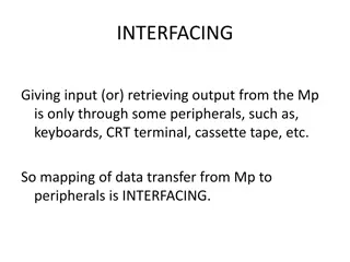
Memory-Mapped Input/Output in Computing Platforms
Memory-mapped input/output allows devices to be mapped to memory addresses, enabling data transfer between the CPU and external devices. This mechanism involves registers in memory cells, such as for a keyboard, where key presses are stored and processed. Implementing memory-mapped I/O requires consideration of reserved memory bits and stack management. Techniques like busy waiting are used for inputting data, but they have drawbacks like limiting multitasking and consuming power inefficiently compared to modern CPUs.

Download Presentation

Please find below an Image/Link to download the presentation.
The content on the website is provided AS IS for your information and personal use only. It may not be sold, licensed, or shared on other websites without obtaining consent from the author.If you encounter any issues during the download, it is possible that the publisher has removed the file from their server.
You are allowed to download the files provided on this website for personal or commercial use, subject to the condition that they are used lawfully. All files are the property of their respective owners.
The content on the website is provided AS IS for your information and personal use only. It may not be sold, licensed, or shared on other websites without obtaining consent from the author.
E N D
Presentation Transcript
Lecture 12 Input/Output (programmer view) Computing platforms Novosibirsk State University University of Hertfordshire D. Irtegov, A.Shafarenko 2018
Memory-mapped input/output Device can be mapped to memory address In next semester we will see what mapping actually means For now, let s imagine that memory cell 0xf3 is not a memory cell But a register of external device When you read or write this register, device can perform some action Or vice versa, when a device performs some action, data are written to the register (and you can read it later)
Simple device a keyboard Actually, not so simple (schematics is present in CdM-8 book) When you press the key, 7-bit ASCII code is written to latch register And 8-th bit of the register is set to 1 (strobe bit). When you (CPU) read the register (cell at 0xf3), strobe bit is cleared This way you can know if the new key was pressed Or the same key was pressed several times
Things to consider For memory-mapped I/O, CdM-8 reserves upper 16 bits of memory This allows for 16 devices, or, more specifically, 16 I/O registers Single device can have several I/O registers Or two devices can share one address for their registers (e.q. one device maps register for write operations and another for reading) We must move stack below i/o page before doing any push and pop Use addsp, not 16 push commands!
How to actually input the data? ldi r0, 0xf3 while ld r1, r0 tst r1 stays gt wend This is called busy wait
Why busy wait is good? It works even for simplest hardware (better ways require special hardware support) It is simple to program and debug It is fast
Why busy wait is bad? You cannot do anything else when busy waiting for a single event You must adapt your code when you wait for several events You cannot stop CPU while busy waiting For CdM-8, this is not a problem For real CPU, it leads to high power consumption and heating If all CPU cores of typical modern smartphone will busy wait, they will eat all the battery in < than a hour
Interrupt Interrupt is a hardware mechanism implemented in CdM-8 and most real modern CPU Interrupts allow hardware devices to call software routines Typically, interrupt signals that device has some data for you For example, keyboard has a new key pressed Or network interface has a new data packet received This is different from pure software call, but also very similar Details are different between CPUs and systems Let s discuss CdM-8 interrupts
Interrupts from software point of view Every interrupt-capable device has unique number on range 0 to 7 Every possible value of device numbers selects a byte pair, called interrupt vector By default, interrupt vectors are mapped to upper 16 bytes of memory In Manchester architecture, these are same bytes as used for memory mapped I/O, so you cannot use all 7 interrupts and all 16 register addresses In Harvard architecture, I/O is mapped to data memory, and vectors to program memory
But what happens when interrupt occurs? Device sets IRQ request on CPU input line When CPU finishes every instruction, it polls IRQ request line If interrupts are enabled (we will discuss this later), it retrieves device number Then, instead of next instruction at mem[PC], ioi instruction is executed In some sence, ioi is normal instruction: it has an opcode, it can be inserted in a machine code and executed like any other command This is called software interrupt But during interrupt, no ioi instruction is present at mem[PC] But CPU behaves like it fetched this instruction
Ioi instruction Phase 1 decrement SP for stack push Phase 2 store PC on stack; decrement SP for stack push Phase 3 store PS on stack Phase 4 fetch new PC value from vector s first cell (0xf0 + 2R) Phase 5 fetch new PS value from vector s second cell (0xf1 + 2R) It is similar to jsr, but two registers are saved (PC and PS) You need to use rti instruction to return from ioi routine And call target depends on hardware (device number R) So you can write separate handler routine for every device
What you can do in interrupt handler? Typically, interrupt signals that device has some data for you So you must retrieve the data Some devices require further instructions, what to do next For example, when you read data from the disk, you must tell the disk what sector to read or write next (or not tell anything and disk will be idle) Then you must set some flags so main program will know the data are ready Then you must return to main program (execute an rti instruction) Or you can do something else (we will discuss it in Operating Systems course)
Why interrupts are bad? They are asynchronous They can occur in any moment of program execution It is very easy to write a handler that can break a main program (damage its data) And it is very hard to catch this condition by testing So, there is a mechanism to disable interrupts (a flag in PS register) Interrupt handling is a simplest (and historically first) form of parallel programming, and parallel programming has many pitfalls And most of these pitfalls are hard to avoid There will be courses on concurrency and parallel programming further in our curriculum
Why interrupts are good? You can handle several event sources at same time You do not need to rewrite your program to add another event source You can do something useful when waiting for an event Operating systems use interrupts to implement multithreading and multitasking
Ring buffer A simple technique which helps to avoid many pitfalls of parallel (asynchronous) programming We will hear about ring buffers and queues in Operating Systems course Ring buffer is very easy to implement in assembler In C course you ve seen queue and stack on linked lists In our course, we ve seen stack implementation on array Ring buffer is queue implemented on the array
Ring buffer (continued) (a)? (c)? 0? 1? 2? 3? 0? 1? 2? 3? 0? 1? 2? 3? 0? 1? 2? 3? (b)? (d)? head? pointer? end? pointer? pointer? advancement:? 0 1 2 3 0 ? Figure 13.3: A cyclic buffer of 4 queue elements, of which any 3 can be used at any time. (a) The queue has two items on it, array elements 3 and 0, element 1 is currently free. (b) The queue has two items on it, array elements 1 and 2, element 3 is currently free. (c) The buffer is full: elements 3,0, and 1 have data to be read. (d) The queue is empty. In order to read an item off the queue for processing, first the program checks that the buffer is not empty. If it is not, then the head item is read off using the head-pointer, and the head-pointer is advanced. The reader may question the point of such a complex data structure in a simple matter of transferring keystroke codes byte-by-byte to the processing program. What is the intention of the queue between the data source (i.e. the interrupt service routine we will show below) and the data processing program? Theneed for aqueueliesin thetimingof theevents. Theinterruptsarenot under theprogram scontrol, they may be requested at any time, which depends solely on the external agent, in this case the human pressing keys on thekeyboard. The keyboard in our example has no buffering capacity: it holds only a single ASCII code of the latest keystroke. If the human presses a key again before the code has been processed, it will be overwritten with a new one, and the current key stroke will be lost. This makes it necessary for the platform to respond quickly to keystroke events, which limits the time that the processor may spend doing the work needed to process the key. Obviously if processing a keystroke takes much more time than it does on average, data may well be lost. What we do to safeguard agains data losses is simplify the interrupt service routine to reduce it to mere data acquisition. Once the key code has been read off the keyboard by the ISR, all the routine does is put it on a queue for processing. It is of course important that the ISR is not itself interrupted when it is doing its relatively small job, because if that were to happen, theISR could not be fast enough to complete, besides the fact that the second character may overtake the first one on the way to the queue, invalidating the character sequence. That is why the ISR in our case must make sure that the interrupts are disabled until it has rti ed. It isimportant to understand that queuesdo not improvetheprocessing capacity. In a hypothetical scenario of an extremely slow platform (our simulated oneisonesuch) and a fast human typist, thelatter will sooner or later fill up any space allocated for incoming characters, whether we use interrupts or flag testing in the program. Whereinterruptsand queueshavea positiveadvantageisin a situation when theincoming stream of events is intermittent. At certain times several events may occur in an interval of some duration, and at other times the same interval may see no events happening at all, while on average the rate at which interruptsoccur may below enough for theprocessing to keep pacewith it. In other words, queues, and our cyclic buffer is an implementation of a queue, have the ability to smooth over sudden peaks and troughs of incoming data without affecting the average and consequently the minimum performance requirements for the platform. In this example we use a queue to demonstrate asynchronous behaviour: the human presses keys in her own time, while the program utilises the clock cycles left from the ISR for getting the data processed. 271
How it works? When interrupt handler retrieves the data, it advances end pointer and stores the data. When array ends, it wraps over (this is why it s called a ring buffer) When main program processed the data, it advances head pointer (probably wrapping over) and retrieves the data When head pointer meets end pointer, queue is considered empty (main program must wait using busy wait or wait instruction) Instead of busy wait, main program can tell OS not to schedule it (but again this is topic of another course. We have no OS in our course) When end pointer meets head pointer, queue is considered full (interrupt handler cannot store data and must drop new data)
Ring buffers and queues are everywhere Many smart peripherial devices have internal buffers or queues, so they can send interrupts not so often, and CPU can process their data in batches Many things you will see in networks and operating systems (disc caches, pipes, sockets, network switches and routers) are ring buffers or queues or something built around a ring buffer or queue


")