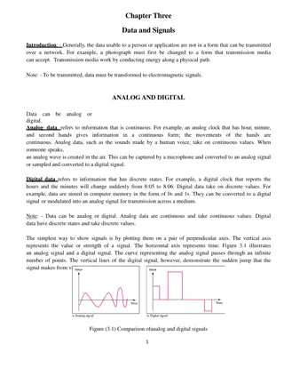
Mathematics for Signals and Systems: Discrete Fourier Transform Matrix
The content delves into the Discrete Fourier Transform (DFT) matrix in the context of signals and systems. It discusses the Fourier matrix, its construction, properties, and the connection to the Fast Fourier Transform (FFT). Exploring applications in engineering and signal processing, the lectures cover topics such as linear system theory, graphs, networks, and more.
Download Presentation

Please find below an Image/Link to download the presentation.
The content on the website is provided AS IS for your information and personal use only. It may not be sold, licensed, or shared on other websites without obtaining consent from the author.If you encounter any issues during the download, it is possible that the publisher has removed the file from their server.
You are allowed to download the files provided on this website for personal or commercial use, subject to the condition that they are used lawfully. All files are the property of their respective owners.
The content on the website is provided AS IS for your information and personal use only. It may not be sold, licensed, or shared on other websites without obtaining consent from the author.
E N D
Presentation Transcript
Maths for Signals and Systems Maths for Signals and Systems Linear Algebra in Engineering Linear Algebra in Engineering Lectures 16 Lectures 16- -17, Tuesday 15 17, Tuesday 15th thNovember 2016 November 2016 DR TANIA STATHAKI READER (ASSOCIATE PROFFESOR) IN SIGNAL PROCESSING IMPERIAL COLLEGE LONDON
Mathematics for Signals and Systems In this set of lectures we will talk about two applications: Discrete Fourier Transforms An application of linear system theory: graphs and networks
The Discrete Fourier Transform (DFT) matrix The ? ? Fourier matrix is defined as: In this matrix we will number the first row and column with 0. We define ? = ? ?2? ???,? = ???. We must stress out that it is better to use the notation ??instead of ?. I have, in general, avoided this notation to make things look simpler but occasionally I used it. ?. For ? is preferable to use polar representation.
The Discrete Fourier Transform (DFT) matrix cont. The parameter ? = ? ?2? below refers to ? = 8 where the points ??= ? ?2?? row (row 1) of the Fourier matrix are shown. ? lies on the unit circle shown below. The case depicted 8 ,? = 0, ,7 of the second We must stress out that the Fourier matrix is totally constructed out of numbers of the form ???.
The Discrete Fourier Transform (DFT) matrix for n=4 The parameter ?4= ? ?2? The quantities inside Fourier matrix are 1,?,,?2,?3,?4,?6,?9. ,?2 4 = ? ?? 2= cos ? + ?sin ? = ?. 2 2 1 1 ( ?)3 ( ?)6 ( ?)9 1 1 ( ?)3 ( ?)2 ( ?)1 1 1 1 1 1 ? 1 1 1 1 1 ? 1 1 1 1 1 ? 1 ? 1 1 1 1 1 ( ?)2 ( ?)4 ( ?)6 ( ?)2 ( ?)0 ( ?)2 ? ?4= = = ( ?)2 ( ?)3 ( ?)2 ( ?)3 1 ? The columns of this matrix are orthogonal. Remember that the inner product of 2 complex vectors is ? ?? = ???.
The Discrete Fourier Transform (DFT) matrix for n=4 cont. I can show that the columns are orthogonal but they are not orthonormal. I can fix this by dividing the Fourier matrix with the length of the rows (columns). In the case of ? = 4 it is 2. Therefore, I can write: 1 1 1 1 1 ? 1 ? 1 1 1 1 1 ?4=1 ? 1 ? 2 We can easily show that ?4??4= ?.
The Fast Fourier Transform (FFT) It can be proven that there is a connection between ?2?and ??. This is expected from the fact that ?2?2= ? ?4? diagonal matrix ?? 2?= ? ?2? ? = ??. It can be shown that: 0 0 0 1 0 0 0 0 0 0 0 1 0 0 0 1 0 0 0 1 0 0 0 permutation matrix ?2? ?? ?? ?? ?? ?? ?? ?? ?? ?2? = 0 1 When ?2? is multiplied by a column vector in order to obtain the Fourier Transform of the signal, we require (2?)2multiplications. When ?2? is decomposed as above, ?2?does not contribute to multiplications, ?? ?? ?? ?? ? multiplications. In total 2 (?)2+? < (2?)2. requires 2 (?)2multiplications and ?? ?? ?? requires ??
The Fast Fourier Transform (FFT) cont. In the previous analysis the matrix ??is defined as: We start requiring (2?)2multiplications and manage to reduce them to 2 (?)2+? multiplications.
The Fast Fourier Transform (FFT) cont. The next step is to break the ??down. We use the above idea recursively. ?? ?? ?? ?? ??/2 ??/2 ?? ?? ??/2 ??/2 ?? ?? ?2? = ?2?= ??/2 ??/2 ??/2 ??/2 ?? ?? ?? ?? ?? ?? ?? ?? ?? ?? = ?2? ??/2 ??/2 ??/2 ??/2 ??/2 ??/2 ??/2 ??/2 ?? ?? We started with (2?)2multiplications and manage to reduce them to 2 (?)2+? multiplication. Now the ?2multiplications are reduced to 2 (?/2)2+?/2 multiplications.
The Fast Fourier Transform (FFT) cont. We can carry on this recursive procedure until we reach 1 1 Fourier matrices. We will have a large number of matrices piling up. It can be proven that if we start with a matrix of size ? ? the total number of multiplications is reduced to 1 2?log2(?) Consider ? = 1024 = 210. In that case ?2> 1,000,000. 1 21024log21024 = 5 1024. We reduced the multiplications from 1024 1024 to 5 1024, i.e., by a factor of 200. The Fast Fourier Transform is one of the most important algorithms in modern scientific computing.
Directed graphs and networks: The incidence matrix A graph is a mathematical model which consists of a set of nodes and edges denoted as: Graph={nodes, edges} 2 1 4 4 1 1 3 5 2 3 Graphs are used in various applications. A graph can be represented by a matrix called incidence matrix. 1 0 1 1 0 1 0 1 1 0 1 0 0 0 1 1 1 0 0 0 ? = Each row corresponds to an edge. Row numbers are edge numbers. Each column corresponds to a node. Column numbers are node numbers. The element ???= 1 if an arrow points towards node ? accross edge ?. The element ???= 1 if an arrow leaves node ? accross edge ?.
Types of graphs A graph where every pair of nodes is connected with an edge is a complete graph. It has the maximum number of edges ? =1 edges and ? is the number of nodes. 2?(? 1) where ? is the number of A graph without closed loops is a tree. It has the minimum number of edges ? = ? 1.
Directed graphs and networks: The incidence matrix. The graph given previously is neither a complete graph nor a tree. 1 4 4 1 2 1 3 5 2 3 Let us focus again on the incidence matrix. 1 0 1 1 0 1 0 1 1 0 1 0 0 0 1 1 1 0 0 0 ? = Observe that Row 3 = Row 1 + Row 2. We also observe that edges 1, 2 and 3 form a closed loop. We can make the statement that closed loops correspond to dependent rows. Independent rows come from trees. rank ? = 3. Independent rows are 1, 2, 4 or 1, 2, 5 or 1, 4, 5 or 2, 4, 5. Furthermore, rank ? = 3 tells us that after 3 edges we start forming loops.
Graphs and networks. Potential differences Ax Let us find the null space of the matrix that corresponds to the graph of interest: ?2 ?1 ?3 ?2 ?3 ?1 ?4 ?1 ?4 ?3 1 0 1 1 0 1 0 1 1 0 1 0 0 0 1 1 ?1 ?2 ?3 ?4 1 0 0 0 = ?? = ? = ? In a real life circuit ?? is a vector of potential or voltage differences. If the graph represents and electronic circuit, the elements of vector ? may represent potentials at nodes (e.g. voltages). ?? ??represents the difference in potential across certain edges. We see that a solution of the above system is ? = 1 The null space is formed by vectors ? 1 The solution to the above system is obtained subject to a scalar ?. Since ? = 4 and and dim ? ? = 1, we see again that rank ? = 3 . By fixing the potential at node one to 0 we remove the first column and we solve for the remaining potentials. In Electrical Engineering this is translated as node 1 been grounded . 1?. 1 1 1?and dim ? ? = 1 . 1 1
Graphs and networks: KirchoffsCurrent Law (KCL) Let us consider the equation ?1 ?2 ?3 ?4 ?5 1 1 0 0 0 1 0 1 0 1 0 0 1 0 0 1 1 0 ??? = 0 = ? 1 1 The vector ? represents currents across the edges (or it could represent a force). The equation ??? = 0 represents Kirchoff s Current Law (KCL): KCL: Current that flows in is equal to current that flows out at each node. Note that there is a matrix ? that connects currents and potential differences at the edges, and represent Ohm s law: ? = ??. We will talk about this later.
Graphs and networks: KirchoffsCurrent Law (KCL) cont. The equation ??? = 0 is Kirchoff s Current Law. 1 4 4 ?1 ?2 ?3 ?4 ?5 1 1 2 1 1 0 0 0 1 0 1 0 1 0 0 1 0 0 3 5 1 1 0 2 3 = ? 1 1 The first equation refers to node one and indicates that the net current flow is zero. Similarly we get: ?1 ?3 ?4= 0 ?1 ?2= 0 ?2+ ?3 ?5= 0 ?4+ ?5= 0
Graphs and networks: KirchoffsCurrent Law cont. The three solution vectors below, that satisfy Kirchoff s Current Law, represent total current running across the three possible loops. 1 1 0 0 1 1 1 0 1 4 4 1 1 2 , , 3 1 0 0 5 2 1 1 1 1 3 We can see that the third solution (current running across the big external loop 3) is not independent from the first two solutions. The null space of ??is, therefore, two dimensional, which is the same as the number of small loops. This is expectable also from the fact that: dim(?(??)) = ? ? = 5 3 = 2
Graphs and networks: row space of incidence matrix Consider the columns space of ??which is the row space of ?. 1 4 4 1 1 0 0 0 1 0 1 0 1 0 0 1 0 0 1 1 1 0 1 2 ??= 3 5 1 1 2 3 The pivot columns of ??are located on the first, second and the fourth columns. These are associated with edges that form a graph without loops. As mentioned this graph is called a tree. The following relationships hold: dim(?(??)) = ? ? #small loops = #edges (#nodes 1) #nodes #edges + #small loops = 1. This relationship is known as Euler s formula.
Real networks: Ohms Law In real life networks we have: current=? potential differences. ? is the so called conductance. It tells us how easily flow gets through an edge (high for metal, low for plastic etc.) Current through an edge is a function of the conductance across this edge only and the potential difference across the edge. Therefore, each edge is associated with a conductance. This yields ? = ??, with ? being a diagonal matrix. The relationship ? = ??, is the so called Ohm s Law.
Summary In real life networks we have: Potential differences: ? = ?? Ohm s Law: ? = ?? Kirchoff s Current Law: ??? = ? The above three equations can be merged in a single equation as follows: ??? = ? ???? = ? ????? = ?
