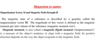
Magnetic Materials in Electrical Machines
L
e
c
t
u
r
e
0
6
Magnetic Classification of Materials
1
The most Important question
showing the importance of these
materials is:
Why all the electrical
machines like (Motors,
generators or
transformers) are made
of an
iron
core?
2
Suppose the current increased gradually,
what will
happen if the tube is glass instead of steel???
3
4
Materials Magnetic Characteristic
Linear Characteristic
Nonlinear Characteristic
Diamagnetic
μr ≤ 1
Paramagnetic
μr ≥ 1
Ferromagnetic
μr >> 1
Characteristics of
f
erromagnetic
,
p
aramagnetic
Vacuum and
d
iamagnetic
5
What is the reason for this behavior of the iron core?
Why the flux density increased with iron core?
The answer is that happen due to the crystal lattice of
the ferromagnetic material
.
6
7
Magnetic domain of grain oriented
electrical silicon steel
8
Micrograph of metal surface showing magnetic domains, with red
and green stripes denoting opposite magnetization directions.
9
10
11
12
13
14
15
The typical (B-H) curve and the permeability
curve of ferromagnetic material
16
T
h
e
t
y
p
i
c
a
l
s
h
a
p
e
o
f
t
h
e
m
a
g
n
e
t
i
z
a
t
i
o
n
c
u
r
v
e
a
t
r
o
o
m
t
e
m
p
e
r
a
t
u
r
e
17
18
Permeability as a function of magnetizing force
for different materials
19
E
f
f
e
c
t
o
f
t
e
m
p
e
r
a
t
u
r
e
o
n
t
h
e
m
a
g
n
e
t
i
c
c
h
a
r
a
c
t
e
r
i
s
t
i
c
s
o
f
f
e
r
r
o
m
a
g
n
e
t
i
c
m
a
t
e
r
i
a
l
s
20
21
22
23
24
25
Magnetic lines of force have a number of important properties, which
include:
•
They seek the path of least resistance between opposite magnetic
poles. In a single bar magnet as shown to the right, they attempt to
form closed loops from pole to pole.
•
They never cross one another.
•
They all have the same strength.
•
Their density decreases (they spread out) when they move from an
area of higher permeability to an area of lower permeability.
•
Their density decreases with increasing distance from the poles.
•
They are considered to have direction
as if flowing, though no
actual movement occurs
.
•
They flow from the south pole to the north pole within a material
and north pole to south pole in air.
26
Why we study the above relations?
What is the gain of this study?
Is there any benefit?
Answer:
Notice the following applications!
How can engineers design these equipments?
The First Step To Design Such Equipments, You Have To Study the “
Magnetic Circuit
”
27
The first question arises here is that:
What is the relation between the terms (
Magnetic
) and (
Circuits
)??????
Answer:
The following table show this relation:
Hence, the magnetic device can be considered as a “
magnetic circuit
” analogous to the
“
electric circuit
”.
28
29
30
34
Repeat the previous example Q1 assume
no air-gap
Discuss the obtained results
The significance of iron cores in electrical machines like motors, generators, and transformers. Understand the behavior of ferromagnetic materials, the B-H curve, and magnetic domains in grain-oriented electrical steel. Discover why the flux density increases with iron cores due to the crystal lattice structure.

Download Presentation

Please find below an Image/Link to download the presentation.
The content on the website is provided AS IS for your information and personal use only. It may not be sold, licensed, or shared on other websites without obtaining consent from the author.If you encounter any issues during the download, it is possible that the publisher has removed the file from their server.
You are allowed to download the files provided on this website for personal or commercial use, subject to the condition that they are used lawfully. All files are the property of their respective owners.
The content on the website is provided AS IS for your information and personal use only. It may not be sold, licensed, or shared on other websites without obtaining consent from the author.
E N D
Presentation Transcript
Lecture 06 Magnetic Classification of Materials 1
The most Important question showing the importance of these materials is: Why all the electrical machines like (Motors, generators or transformers) are made of an iron core? 2
Suppose the current increased gradually, what will happen if the tube is glass instead of steel??? 3
Materials Magnetic Characteristic Linear Characteristic Nonlinear Characteristic Diamagnetic r 1 Ferromagnetic r >> 1 Paramagnetic r 1 4
B-H Curve of Ferromagnetic Material 2 1.8 1.6 1.4 Flux Density (T) 1.2 1 0.8 0.6 0.4 0.2 0 0 2500 5000 7500 10000 12500 15000 17500 20000 Magnetizing Force (A/m) Characteristics of ferromagnetic, paramagnetic Vacuum and diamagnetic 5
What is the reason for this behavior of the iron core? Why the flux density increased with iron core? The answer is that happen due to the crystal lattice of the ferromagnetic material. 6
Magnetic domain of grain oriented electrical silicon steel 8
Micrograph of metal surface showing magnetic domains, with red and green stripes denoting opposite magnetization directions. 9
B-H Curve of Ferromagnetic Material 2 1.8 1.6 1.4 Saturation Region Flux Density (T) 1.2 1 0.8 0.6 0.4 0.2 0 0 2500 5000 7500 Magnetizing Force (A/m) 10000 12500 15000 17500 20000 10
Easy Magnetization Region Linear Region B-H Curve of Ferromagnetic Material 2 1.8 1.6 1.4 Saturation Region Hard Magnetization Region Nonlinear Region Flux Density (T) 1.2 1 0.8 0.6 Air-gap Line 0.4 0.2 0 0 2500 5000 7500 Magnetizing Force (A/m) 10000 12500 15000 17500 20000 The magnetizing force (H) measured in (Am 1) or in (Oersted ). Where 1 Oe=1000/4 =79.577 80Am 1 The flux density (B) measured in (T). Where T =Wb m 2 Mx cm 2and Wb = 108 Mx also, T = 104G , since G = 11
In order to know the effect of the core material on the flux density inside a coil, proceed as follows: Refer to the (B-H) curve and compare between the values of (B) for air cored coil and iron cored coil for the same (H) as shown ????=???? ? Then ????= ??: Is known as (The Relative Permeability), which is a unitless number representing the factor of increasing the flux density of certain ferromagnetic material. ? , while ?????=????? ????? ?????? ?????=????? ????= ?? 13
From the previous discussion, it is clear that: ??=?? ?? Where ?? is the permeability of iron ?????, and ?? is the permeability of vacuum ????. The following table represents the relative permeability of different alloys of materials. In general the permeability of any material ? is: ? = ?? ?? 14
Medium Relative Permeability Metglas 2714A (annealed) 1000000 Iron (99.95% pure Fe annealed in H) 200000 Nanoperm 80000 Mu-metal 50000 Cobalt-Iron (high permeability strip material) 18000 Permalloy 8000 Iron (99.8% pure) 5000 Electrical steel 4000 Ferritic stainless steel (annealed) 1000-1800 Martensitic stainless steel (annealed) 750-950 Ferrite (manganese, zinc) 640 Ferrite (nickel, zinc) 16-640 Carbon Steel 100 Nickel 100-600 Martensitic stainless steel (hardened) 40-95 Austenitic stainless steel 1.003-7 Neodymium magnet 1.05 Platinum 1.000265 Aluminum 1.000022 Wood 1.00000043 Air 1 Concrete (dry) 1 Vacuum 1 Hydrogen 1 Teflon 1 Sapphire 0.99999976 Copper 0.999994 Water 0.999992 Bismuth 0.999834 Superconductors 0 15
The typical (B-H) curve and the permeability curve of ferromagnetic material 16
The typical shape of the magnetization curve at room temperature 17
Permeability as a function of magnetizing force for different materials 19
Effect of temperature on the magnetic characteristics of ferromagnetic materials 20
? = ? . (1) ? =? ? ? . .. (2) ? ? .. (3) ? = ? ... (4) ? = ? ? ? ?= ? ? ? ? = ? ? ? ? ? ? ? ? ? ? = .. .. (5) ???? =????????????? ????? ???????? ??????????=??????????? ????? ?????????? 22
Permeability in the SI Quantity name Permeability Quantity symbol Unit name Henry per meter H m 1 kg m 1s-2 A-2 Unit symbols Base units Reluctance in the SI Reluctance, Magnetic Resistance Quantity name S Quantity symbol Unit name Per Henry A Wb 1=H 1 kg 1s2 A2 Unit symbols Base units 23
Flux Density ? ? = ? : In Weber (Wb) ?: In square meters m2 ?: In Teslas (T) 1 Tesla= 1 Wb.m 2 1T=104G Wb=108Mx 24
Magnetic lines of force have a number of important properties, which include: They seek the path of least resistance between opposite magnetic poles. In a single bar magnet as shown to the right, they attempt to form closed loops from pole to pole. They never cross one another. They all have the same strength. Their density decreases (they spread out) when they move from an area of higher permeability to an area of lower permeability. Their density decreases with increasing distance from the poles. They are considered to have direction as if flowing, though no actual movement occurs. They flow from the south pole to the north pole within a material and north pole to south pole in air. 26
Why we study the above relations? What is the gain of this study? Is there any benefit? Answer: Notice the following applications! How can engineers design these equipments? The First Step To Design Such Equipments, You Have To Study the Magnetic Circuit 27
The first question arises here is that: What is the relation between the terms (Magnetic) and (Circuits)?????? Answer: The following table show this relation: Magnetic Device Electric Circuit The exciter of the magnetic device is a coil fed by a DC voltage source to produce a magnetomotive force (mmf) or (f) in (NI) known as Ampere Turns of the coil. The exciter of the electric circuit is a DC voltage source, electromotive force (emf) or (e) in Volts, feeding the circuit. known as the This coil will produce Magnetic Flux ? inside the core of the device. This source will produce Electric Current ? in side the circuit. The initiation of the flux in the core of the device will be due to the properties of the magnetic core the Reluctance (?) : This current will be opposed by the circuit properties the Resistance (?) : ? = ?? ?= ? ? ?? ? = ?? The determination of the magnetic flux in the magnetic core due to the relation: ? =??? ? The determination of the electric current in electric circuit, due to the relation: ? =??? ? =? =? ? ? Hence, the magnetic device can be considered as a magnetic circuit analogous to the electric circuit . 28
? (A) ? (?) emf (V) ? =??? =? ?=? ? =??? =? ? ? 29 ? ?
Magnetic Circuit Problems Q1:The magnetic circuit shown in Fig. 1 has dimensions??= ??=9 cm2, ? = 0.050 cm, lc = 30 cm, and N = 500 turns. Assume the value?? = 70,000 for core material. (a) Find the reluctances ?and ?. For the condition that the magnetic circuit is operating with Bc = 1.0 T, find (b) the flux ? and (c) the current i. Air gap length Area Figure (1)
Solution: a.The reluctances can be found from: ?? ?????? 70.000(4? 10 7)(9 10 4)= 3.79 103A.Turns 0.3 A T Wb 1 ?= = Wb 5 10 4 ? (4? 10 7)(9 10 4)= 4.42 105A.Turns A T Wb 1 ?= = ???? Wb Note: =4.42 105 3.79 103= 116.623 ? ? b.From ? = ????= 1.0(9 10 4)= 9 10 4Wb c.? =??? =?? =9 10 4(4.46 105) 500 =? ?+ ? ? =? = 0.08 A ? ?
Repeat the previous example Q1 assume no air-gap Discuss the obtained results 34


 curve and the permeability")


")