Magnetic Field Calculation and Parameters for Injection/Extraction Kicker CR
This document provides detailed information on the injection/extraction kicker CR used by Aleksey Kasaev at the BINP-FAIR-GSI workshop in 2014. It includes main parameters of the kicker, magnetic field calculations, ferrite parameters, magnetic field distribution, and time cycles of operation. Additionally, it discusses the power supply scheme with different methods for constructing the pulse forming network (PFN).
Download Presentation

Please find below an Image/Link to download the presentation.
The content on the website is provided AS IS for your information and personal use only. It may not be sold, licensed, or shared on other websites without obtaining consent from the author.If you encounter any issues during the download, it is possible that the publisher has removed the file from their server.
You are allowed to download the files provided on this website for personal or commercial use, subject to the condition that they are used lawfully. All files are the property of their respective owners.
The content on the website is provided AS IS for your information and personal use only. It may not be sold, licensed, or shared on other websites without obtaining consent from the author.
E N D
Presentation Transcript
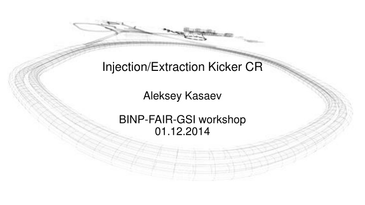
Injection/Extraction Kicker CR Aleksey Kasaev BINP-FAIR-GSI workshop 01.12.2014
Main parameters of the kicker Maximum magnetic field, mT Direction of kick Horizontal gap X, sm Vertical gap Y, sm Integrated field of kicker, mT x m Number of modules Effective length , sm Length of ferrite, sm Inductance of module, H Peak current on the kickers plates, kA Rise/fall of pulse (requirement), nsec Maximum pulse duration, sec PFN impedance (requirement), Ohm dI/dt for switch (not less), kA/ s Maximum Charging voltage of PFN, kV Type of thyratron Magnetic Material Ferrite thickness Field inhomogeneity, no more Undershoot, no more 46.3 horizontal 18 10 167 6 60 50 1.3 3.7 200 0.8 6.5 18.5 47 CX2610 8C11 3 sm 2% 1.5%
Parameters of the ferrite Thickness of ferrite 30 mm Weight of ferrite per module 50 kg Weight of one block C-type 25 kg Total weight of ferrite for 6 modules 300 kg For calculating take the maximum magnetic field equal 0.15T
Magnetic field distribution along axis X Window dimension along axis X 180 mm Nominal magnetic field Field nonuniformity in this direction 0.1% 46.3 mT
Magnetic field per kicker section Length of the module 50 sm. The spacing between modules 10 sm. Integrated field effective 83 mTm. Calculated in 2D FEMM.
The time cycle of injection/extraction The time cycle of kicker in the antiproton mode The time cycle of kicker in the RIB mode
Scheme of the Power Supply Three methods of PFN construction: Cable line connected in parallel for to obtain requirement wave impedance. Line with concentrated parameters allow to get the requirements parameters with compact dimensions. Special line with distributed parameters - also as previous variant. This scheme provides a different polarity and duration of the current pulse. PFN may be consist from the cable line with nominal working voltage 47 kV. Parameters of the pulse forming line PFN Impedance 6.7 Ohm PFN capacity 450 nF Maximum charging voltage 47 kV
Parameters of the switch Peak forward anode voltage Peak forward anode current Rate of rise anode current 20 kA/ sec 47 kV 3.7 kA Variants of switch: Thyratron Semiconductor Pseudospark Thyratron variant Type CX2610 Peak forward anode voltage 55 kV Peak forward anode current 10 kA Rate of rise anode current 100 kA/ sec The peak inverse voltage, including spike, must not exceed 5 kV for the first 25 ms after the anode pulse. It is necessary to put a diode in parallel to the thyratron. produced by E2V Trigger module MA2709A produced by E2V
Charging scheme V1 - power supply (nominal voltage 260V, nominal power 600W) C1, C2 - capacity storage S1, S4 - charging switch (nominal current 150A) L1-L4 pulse transformer (transformation coefficient 192) C2- PFN capacity Two capacity storage allow to use low power supply. The time charging of this capacities 1sec.
