JCB TM320, TM420 Telescopic Wheel Loader Service Repair Manual Instant Download (TM320 SN from 2508700 to 2509499, 2681926 and up; TM420 SN 2454001 and up)
Please open the website below to get the complete manualnn//
Download Presentation

Please find below an Image/Link to download the presentation.
The content on the website is provided AS IS for your information and personal use only. It may not be sold, licensed, or shared on other websites without obtaining consent from the author. Download presentation by click this link. If you encounter any issues during the download, it is possible that the publisher has removed the file from their server.
E N D
Presentation Transcript
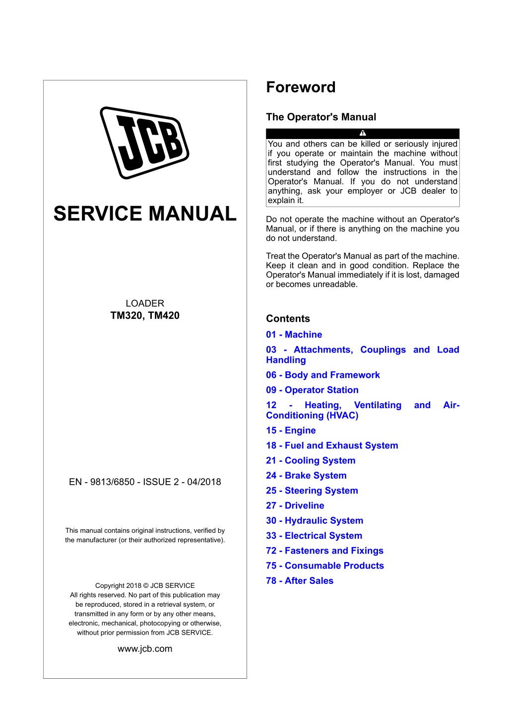
Foreword The Operator's Manual You and others can be killed or seriously injured if you operate or maintain the machine without first studying the Operator's Manual. You must understand and follow the instructions in the Operator's Manual. If you do not understand anything, ask your employer or JCB dealer to explain it. SERVICE MANUAL Do not operate the machine without an Operator's Manual, or if there is anything on the machine you do not understand. Treat the Operator's Manual as part of the machine. Keep it clean and in good condition. Replace the Operator's Manual immediately if it is lost, damaged or becomes unreadable. LOADER TM320, TM420 Contents 01 - Machine 03 - Attachments, Couplings and Load Handling 06 - Body and Framework 09 - Operator Station 12 - Heating, Ventilating Conditioning (HVAC) 15 - Engine 18 - Fuel and Exhaust System 21 - Cooling System 24 - Brake System 25 - Steering System 27 - Driveline 30 - Hydraulic System 33 - Electrical System 72 - Fasteners and Fixings 75 - Consumable Products 78 - After Sales and Air- EN - 9813/6850 - ISSUE 2 - 04/2018 This manual contains original instructions, verified by the manufacturer (or their authorized representative). Copyright 2018 JCB SERVICE All rights reserved. No part of this publication may be reproduced, stored in a retrieval system, or transmitted in any form or by any other means, electronic, mechanical, photocopying or otherwise, without prior permission from JCB SERVICE. www.jcb.com
27 - Driveline 06 - Semi-Automatic Gearbox 12 - Clutch - Ratio 12 - Clutch - Ratio Disassemble and Assemble Special Tools Description Circlip Assembly Tool Figure 567. Part No. 998/11334 Qty. 1 A Main shaft clutch Disassembly The numerical sequence is a guide to the disassembly procedure. 1. Remove and discard the O-ring seals 1. 2. To check the clutch plates. 2.1. Remove the circlip1 from the clutch drum. 2.2. Lift off the thick pressure counter plate then the seven friction plates and seven counter plates. A Tube 3. Remove and check the roller bearing race. If necessary discard it. 5. Cut out a small portion of the tube, to allow access, to release the circlip 2. 4. Use either the circlip assembly tool or a tube of suitable diameter to install over the top spring cup. Special Tool: Circlip Assembly Tool (Qty.: 1) 6. With the clutch drum located in the press, compress the spring sufficiently to allow the circlip 2 to be released. 7. When the circlip 2 is released, remove it from the shaft with the spring cup, spring and the lower spring cup. 8. If necessary the clutch operating piston may be removed by compressed air blown through the drilling in the end of the clutch shaft. 9. Remove and discard the clutch piston O-ring seal 2 and seal 3. 27 - 126 9813/6850-2 27 - 126
27 - Driveline 06 - Semi-Automatic Gearbox 12 - Clutch - Ratio Figure 568. B C D E F G H J K L N P Q R M S Item G H J K L M N Description Upper spring cup Circlip 2 Spring Lower spring cup Piston Clutch shaft O-ring seal 2 Table 242. Item B C Description Circlip 1 Thick pressure counter plate Friction plate Counter plate Roller bearing race D E F 27 - 127 9813/6850-2 27 - 127
https://www.ebooklibonline.com Hello dear friend! Thank you very much for reading. Enter the link into your browser. The full manual is available for immediate download. https://www.ebooklibonline.com
27 - Driveline 06 - Semi-Automatic Gearbox 12 - Clutch - Ratio Ratio Clutches Item P Q R S Description O-ring seal 3 Housing Gallery port O-ring seal 1 Disassembly 1. For the remaining two ratio clutches follow the same disassembly procedure as above. 2. The only difference is the retention of the support taper roller bearing which for each clutch is held in place by a machined cap. Assembly Assembly is the opposite of the disassembly procedure with the following precautions. Assembly 1. Install the new clutch piston O-ring seals 2 and seal 3 to the piston. 1. Clutch 1 and clutch 2 assembly. 1.1. Use a mandrel to carefully push the taper bearing 1 into its position. 2. Lubricate the new seals and push the piston into the housing by hand. 1.2. Rotate the roller cage as the bearing is pushed into place to make sure that the mandrel does not foul and distort the cage. 3. Put the lower spring cup over the central spigot of the piston. 4. Replace the spring and the top spring cup. 1.3. Put the new O-ring seal 4 into the grooves in the cap 1. 5. Keep the circlip 2 on the top cup ready for installation. Figure 569. 6. Use the tube with a cutout to compress the spring. W X 7. Locate the cutout to give access for circlip 2. V 8. Install the circlip 2 and make sure that it is seated correctly in the groove. U 9. New clutch friction plates must be soaked in oil before assembly. T 10. Install the first counter plate to the clutch drum followed by the friction plate. 11. Alternately install all fourteen plates. 12. Use a scrap splined drive hub to align the splines of the friction plates. 13. Install the thick counter plate at the top of the assembly followed by the circlip 1. 14. Check the free play clearance of the clutch plates and it must be within the specified limit. Dimension: 3 3.5 mm T Taper bearing 1 U O-ring sea l4 V Cap 1 W Capscrews 1 X O-ring seals 5 15. You can adjust the clearance by either changing the thick pressure plate from 6.0mm (0.24in) thick version to 6.5mm (0.26in) thick or by the addition of a shim counter plate installed immediately under the thick pressure plate. 1.4. Two capscrews 1 hold the cap 1 in place. 16. Once the clutch is assembled completely then apply compressed air to the gallery port in the end of the shaft to check the clutch operation. 1.5. Tighten the capscrews 1 to the correct torque value. 1.6. Put two new O-ring seals 5 into the groves in cap 1. 27 - 128 9813/6850-2 27 - 128
27 - Driveline 06 - Semi-Automatic Gearbox 12 - Clutch - Ratio 2. Clutch 3 and clutch 4 assembly. 2.1. Use a mandrel to carefully push the taper bearing 2 into its position. 2.2. Rotate the roller cage as the bearing is pushed into the place to make sure that the mandrel does not foul and distort the cage.. 2.3. Put the new O-ring seal 6 into the grooves in the cap 2. Figure 570. Z Y AA AC AB Y Z AA Cap 2 AB Capscrews 2 AC O-ring seals 7 Taper bearing 2 O-ring seal 6 2.4. Two capscrews 2 hold the cap 2 in place. 2.5. Tighten the capscrews 2 to the correct torque value. 2.6. Put two new O-ring seals 7 into the groves in cap 2. Table 243. Torque Values Item W AB Description Capscrews1 Capscrews2 Nm 18 45 27 - 129 9813/6850-2 27 - 129
27 - Driveline 06 - Semi-Automatic Gearbox 13 - Clutch - Master 13 - Clutch - Master Remove and Install Special Tools Description Clutch Pack Retainers Mandrel Locking Plates Remove and Install ..................................... 27-130 Disassemble and Assemble ........................ 27-136 Part No. 892/01048 892/01050 892/01052 Qty. 2 1 2 Consumables Description JCB Multi-Gasket Part No. 4102/1212 Size 0.05 L Remove 1. Put the gearbox on a suitable manipulator. Rotate the gearbox until the clutch is in the top position. 2. Remove all the cover attaching bolts and then install the M10 jacking bolts1 (x3). 3. Screw all the jacking bolts evenly until the cover is clear of its spigot. Figure 571. E B C A D B G F A Cover attaching bolts (x18) B M10 jacking bolts1 (x3) C Cover D M10 threaded lifting eye (x2) E Oil seal2 F Cover O-ring seal G O-ring1 seal 4. Install the M10 threaded lifting eyes to lift the cover. 27 - 130 9813/6850-2 27 - 130
27 - Driveline 06 - Semi-Automatic Gearbox 13 - Clutch - Master 5. Carefully lift off the cover and make sure that you keep it square to the housing. 9. Prise out and discard the oil seal2 carefully and make sure that the seal housing in the cover is not damaged. 6. Make sure that you remove and discard all the O-ring1 seals. 10. Install the special locking plates to prevent the clutch assembly from rotating. Special Tool: Locking Plates (Qty.: 2) 7. Remove the jacking bolt. 8. Remove and discard the cover O-ring seal. Figure 572. H A J H L K A Cover attaching bolts (x18) J Clutch assembly L Housing H Special screws K Special locking plate 11. Use the cover attaching bolts and the special screws that are supplied with the locking plates, to lock the clutch assembly to the housing. 12. Remove all the clutch drum bolts. 27 - 131 9813/6850-2 27 - 131
27 - Driveline 06 - Semi-Automatic Gearbox 13 - Clutch - Master Figure 573. Figure 574. T R N M S U P Q V M Clutch drum bolts (x12) N Plug1 P M8 threaded lifting eye (x2) Q Clutch drum R Special pack retainers (x2) S Clutch plates T Thrust washer1 U Plate carrier V Thrust washer2 13. Remove the locking plate. 14. Install the M8 threaded lifting eyes to the clutch drum. 15. Attach suitable lifting equipment to the clutch drum. 18. Remove the carrier together with the clutch plates and the thrust washer1. 16. Carefully remove the clutch drum, hub and the pressure plate assembly. 19. Remove the thrust washer2. 17. Install the special pack retainers to the clutch plate carrier. Special Tool: Clutch Pack Retainers (Qty.: 2) 20. Remove the button head capscrews. 21. Remove the oil baffle plate. 22. Rotate the drum carrier to align the five holes with countersunk capscrews. 23. Remove the countersunk capscrews. 27 - 132 9813/6850-2 27 - 132
27 - Driveline 06 - Semi-Automatic Gearbox 13 - Clutch - Master Figure 575. Figure 576. AB W X L M AC Z Y AD Z M AA Z AB L M L W X Y Z AA Drum carrier AB M10 jacking bolts2 (x3) Clutch drum bolts (x12) Housing Button head capscrews (x5) Oil baffle plate Countersunk capscrews JCB multigasket L Z AB Verbus-ripp bolts (x12) AC O-ring2 AD Cross drilling blanking plug2 Housing JCB multigasket 28. The clutch house removal. 28.1. Remove and discard all the Verbus-ripp bolts. 24. Install the M10 jacking bolts2 and jack the drum carrier to remove it from the housing. 28.2. Use a soft faced hammer to separate the housing from the PTO/splitter gearbox. 25. Make sure that you install the drum bolts that will assist you to lift the drum carrier clear of the housing. 28.3. Remove the clutch housing. 29. After you remove the clutch from the housing there will be three main sub assemblies. 26. The drum carrier will be removed completely with the PTO (Power Take-Off) input gear and the bearing. 29.1. Remove the Clutch drum, hub and pressure plate sub-assembly. Refer to Figure 577. 27. It is not necessary to remove the clutch housing unless it is damaged or the PTO/splitter gearbox needs to be disassembled. 27 - 133 9813/6850-2 27 - 133
27 - Driveline 06 - Semi-Automatic Gearbox 13 - Clutch - Master Figure 577. Figure 579. Install Installation is the opposite of the removal procedure but make sure that additionally you follow the instructions below. 29.2. Remove the clutch plates and plate carrier sub-assembly. Refer to Figure 578. 1. If it is necessary to replace the clutch housing with a new one then make sure that the cross drilling blanking plug2 is installed to the new housing. Figure 578. 2. Tighten the plug2 to the correct torque value. 3. Make sure that the oil feed cross drillings are clear. 4. Carefully clean all the traces of the sealing compound from the clutch and the smoothshift gearbox housing mating surfaces. 5. Lightly lubricate with oil and install a new O-ring2. 6. Apply even beads of JCB Multigasket to the Smoothshift Gearbox housing (around the outer diameter and around each threaded bolt hole). Consumable: JCB Multi-Gasket 7. Make sure that you install new Verbus-ripp bolts. 29.3. Remove the clutch drum carrier and input gear PTO sub-assembly. 8. Tighten the Verbus-ripp bolts to the correct torque value. 9. Make sure that the clutch components are carefully checked for any signs of wear or damage. 10. If any of the friction or counter plates are damaged or if any of the friction plates are excessively worn (thickness less than 3.5 mm or oil grooves less than 0.1 mm deep) replace the complete set of plates. 27 - 134 9813/6850-2 27 - 134
27 - Driveline 06 - Semi-Automatic Gearbox 13 - Clutch - Master 11. Make sure that the new friction plates are soaked in transmission oil before you install them. 12. Check the thrust washer2 for any signs of wear. 13. If the thickness (3.9mm) or the outside diameter (110.0mm) is less then the mentioned value then install a new thrust washer2. 14. Before you install the new thrust washer2 soak it in the transmission oil for at least an hour. 15. Do not apply any kind of thread locking compound to any of the bolts or screws. 16. Tighten the plug1s to the correct torque value to prevent oil gallery leakage. 17. It is not possible to locate the clutch drum over the clutch plates and carrier assembly inside the housing. 18. First sub-assemble the components on the bench and then use the retainers to hold the assembly together. 19. Before you replace the drum, plates, carrier and hub assembly install the two guide pins to the M10 threaded holes in the drum carrier. 20. Use a special mandrel to install the new oil seal2. Special Tool: Mandrel (Qty.: 1) 21. If the clutch plates are replaced with new ones, check to make sure that the clutch is disengaged before installing the cover 2. 22. Lightly apply oil and install a new O-ring1 and the cover O-ring. Table 244. Torque Values Item A M W Y N N AB AD Description Cover attaching bolt Clutch drum bolt Button head capscrews Countersunk capscrews Plug1(Black) Plug1(Gold) Verbus-ripp bolt Cross drilling blanking plug2 Nm 56 52 12 38 22 12 75 15 27 - 135 9813/6850-2 27 - 135
27 - Driveline 06 - Semi-Automatic Gearbox 13 - Clutch - Master Disassemble and Assemble Special Tools Description Peg Socket Mandrel Clutch Jig Clutch Pack Retainers Guide Rods Slide Hammer Kit 8. Use M6 bolt (x2) and suitable levers to help in removal of the piston. Part No. 892/01045 892/01046 892/01047 892/01048 892/01049 993/68100 Qty. 1 1 1 2 2 1 9. Remove and discard the outer seal from the piston. 10. Remove the socket head capscrews (x8). 11. Use a suitable bar to prevent drum rotation. 12. Use a soft faced hammer to tap out the hub from the drum. Consumables Description JCB Threadlocker and Sealer (Medium Strength) Part No. 4101/0250 4101/0251 Size 0.01 L 0.05 L 13. Remove and discard the O-ring 1 from the drum. 14. Remove the circlip. 15. Use a suitable drift to tap out the blanking disc together with the inner bearing. Master Clutch- Clutch Drum and Hub 16. Remove and discard the O-ring 2. Disassembly 17. Remove and discard the iron sealing ring. 1. Remove the lubrication nozzles. 18. Remove and discard the inner piston seal from the hub. 2. Remove the bolts. 19. Do not remove the outer bearing unless it is to be replaced with a new one. 3. Remove the release springs and the spring pillars then discard the springs. 20. At the time of removal the bearing can be damaged. When the bearing is removed it must be replaced. 4. Remove the oil baffle plate from the locating dowel 1. 5. Remove the pressure plate. 21. To remove the outer bearing, screw in two jacking bolts at their correct location on the hub. 6. Make sure that you do not lose the dowel 1 and dowel 2 22. If the bronze bush is to be replaced, then remove it with a suitable puller and slide hammer. Special Tool: Slide Hammer Kit (Qty.: 1) 7. Remove the piston from the drum. 27 - 136 9813/6850-2 27 - 136
27 - Driveline 06 - Semi-Automatic Gearbox 13 - Clutch - Master Figure 580. L K A K H M L G H W J F E C Y D W B Y X Z S U T L Z P R Q N V 27 - 137 9813/6850-2 27 - 137
27 - Driveline 06 - Semi-Automatic Gearbox 13 - Clutch - Master Item T U V W X Y Z Description Inner piston seal Outer bearing Bronze bush M8 bolt (x2) Dowel 1 Dowel 2 Jacking bolts (x2) Table 245. Item A B C D E F G H J K Description Lubrication nozzles Bolts Springs Spring pillars Oil baffle plate Pressure plate Piston Drum Outer seal Socket head capscrews (x8) Hub O-ring 1 Circlip Blanking disc Inner bearing O-ring 2 Sealing ring Assembly Assembly is the opposite of the disassembly procedure but additionally follow the steps below. 1. Check that the oil feed slots and drillings are clear. L M N P Q R S 2. Check the condition of the pressure plate, if it is excessively scored then replace with a new one. 3. If it is necessary to replace the pressure plate, dowel 1 and dowel 2 must be installed to the plate before assembly. 27 - 138 9813/6850-2 27 - 138
27 - Driveline 06 - Semi-Automatic Gearbox 13 - Clutch - Master Figure 581. K A H M L G W J F E C Y D W B Y X A Lubrication nozzles C Springs E Oil baffle plate G Piston J Outer seal L Hub W M8 bolt (x2) Y Dowel 2 B Bolts D Spring pillars F Pressure plate H Drum K Socket head capscrews (x8) M O-ring 1 X Dowel 1 4. The larger dowel 2 must be tapped into the blind holes on one face of the plate and the smaller dowel 1 must be tapped onto the through holes on the opposite face so that they reach through the plate but do not protrude. 7.1. Put a drop of paraffin in the orifice of the valve. 5. Check the faces of the drive tangs on the drum and if you find any small burrs then carefully use a file to remove the small burrs. 6. Check the pressure relief ball valve in the piston, the ball should be free to move against its spring. 7. Check the pressure relief valve for leakage. Refer to Figure 582. 27 - 139 9813/6850-2 27 - 139
27 - Driveline 06 - Semi-Automatic Gearbox 13 - Clutch - Master Figure 582. 12. Keep the hub square to the drum to avoid damage to the O- ring 1. 13. Install the socket head capscrews. AC 14. Gradually tighten the capscrews to the correct torque value. 15. Align the threaded holes in the piston with the guide hole in the hub. Refer to Figure 584. Figure 584. L G AB AA AA AB AC Valve orifice G L AA Threaded holes in piston AB Guide holes in hub Piston Hub 7.2. There should not be any leakage on the other side of the ball. 7.3. If there is leakage then the piston or the valve assembly must be replaced with a new one. 16. Locate the piston inside its groove. 17. Locate the larger dowel (dowel2) pins on the pressure plate into the drilled holes in the piston. 8. If the bronze bush is to be replaced then make sure that the oil grooves must align with the oil feed drillings in the hub. 18. Use a suitable press to push the pressure plate and the plate will push the piston down. 9. Use a suitable mandrel to push the bush until it is 0.5mm below the end face of the hub. Special Tool: Mandrel (Qty.: 1) 19. Remove the pressure plate and make sure that there is no evidence of damaged seals in the form of small slices of seal material. 10. Lubricate and install a new O-ring 1 to the drum. 20. If damage is suspected, remove the piston, install new seals and then assemble again. 11. Align the oil feed holes in the hub with the oil feed slots in the drum. Refer to Figure 583. 21. Make sure that the pressure plates are aligned correctly. Figure 583. 22. Replace the oil baffle plate on the locating dowel 1. 23. Install new springs. 24. Remove any debris that may have been pushed from the bolt holes into the hub. 25. If the drum and the hub are separated then the outer bearing and the capscrews must be replaced with a new one. 26. Before you install the outer bearing make sure that the spring is installed already. 27 - 140 9813/6850-2 27 - 140
27 - Driveline 06 - Semi-Automatic Gearbox 13 - Clutch - Master 27. Use a suitable press to install the outer bearing and apply force only on to the inner race. Consumable: JCB Threadlocker and Sealer (Medium Strength) 28. Note that the piston rings cannot be installed before the outer bearing. 30. Install new piston rings with extreme care, as the rings can break very easily. 29. Apply one drop of JCB Threadlocker and Sealer to one or two threads from the end, on the lubrication nozzles. 31. Note the interlocking end of the piston rings. Figure 585. AD Z S U T L Z P R Q N V N Q S U L AD Piston ring interlocking end Circlip Inner bearing Sealing ring Outer bearing Hub P Blanking disc R O-ring 2 T Inner piston seal V Bronze brush Z Jacking bolts (x2) Table 246. Torque table Item A B K Description Lubrication nozzles Bolts Socket head capscrews Torque value 15 N m 28 N m 85 N m Master Clutch- Clutch Plates and Plate Carrier 2. The plates can only be removed from one end of the carrier. There are six friction plates and five counter plates. Disassembly 3. If the thrust washer is not removed at the time of removal then remove it now. 1. Remove the friction plates and counter plates from the plate carrier. 27 - 141 9813/6850-2 27 - 141
27 - Driveline 06 - Semi-Automatic Gearbox 13 - Clutch - Master Figure 586. A B C B D A E H C G F B G Item F G H Description Guide rods Threaded hole Clutch pack retainers Table 247. Item A B C D E Description Friction plates Counter plates Plate carrier Thrust washer Clutch drum and hub as- sembly Assembly 1. Before you assemble the friction and the counter plates check them for any signs of damage or wear. 27 - 142 9813/6850-2 27 - 142
27 - Driveline 06 - Semi-Automatic Gearbox 13 - Clutch - Master 2. Friction plates should not be less than 3.5 mm thick or have oil grooves less than 0.1 mm deep. If the friction plate thickness is less then 3.5 mm then it needs to be changed for a new one. Figure 588. E 3. Replace the plates in a set, not as a single piece. 4. Check the thrust washer for wear. 5. If the thickness is less than 2.9mm or the outside diameter is less than 90mm then replace the thrust washer. C G 6. Before you install new friction plates and a new thrust washer soak them in transmission oil for at least one hour. F B 7. Start the assembly with a friction plate followed by a counter plate and so on. G 8. Note the correct orientation of oil slots in the friction plates relative to the plate carrier. Refer to Figure 587. Figure 587. A B Counter plates C Plate carrier E Clutch drum and hub assembly F Guide rods G Threaded hole 10. It is not possible to replace the clutch drum and hub assembly inside the clutch housing unless it is first installed to the plates and plate carrier assembly. 11. Install the thrust washer to the plate carrier. 12. Install two suitable guide rods to the threaded holes in the plate carrier. Special Tool: Guide Rods (Qty.: 2) C A Friction plate C Plate carrier 13. Use suitable lifting equipment to carefully lower the drum and hub sub-assembly over the plates. 9. The counter plates should be positioned relative to the two threaded holes. Refer to Figure 588. 14. Make sure that the guide rods locate through the corresponding holes in the drum. 15. Make sure that the drive tangs on the counter plates engage with the cut-outs in the drum. 16. It may be necessary to rotate the drum and plates slightly to align them. 17. With the drum and hub fully lowered, remove the guide rods and install two special pack retainers to temporarily hold the assembly together. Special Tool: Clutch Pack Retainers (Qty.: 2) 18. Do not use bolts or screws, mistakenly they may be left in the place which can make the clutch inoperative. 27 - 143 9813/6850-2 27 - 143
27 - Driveline 06 - Semi-Automatic Gearbox 13 - Clutch - Master 19. The special retainers prevent further assembly until they are removed. 23.3. Make sure that the bolts are tightened and the splitter input shaft is engaged in the clutch plate carrier. 20. The drum, hub, plates and plate carrier can now be replaced inside the clutch housing as a complete assembly. Refer to: PIL 27-06-13. 23.4. Turn the clutch drum/hub assembly and, at the same time hold the splitter shaft so it does not rotate. Some drag is normal. Master Clutch- Clutch Drum Carrier and Power Take Off Input gear 21. Remove the special retainers and install plugs to the holes in the clutch drum. 22. If the clutch plates are replaced, the plate stack height is changed. Disassembly 1. To remove the stake nut follow the steps below. 23. If the stack height is too high then the clutch will be permanently engaged. Do the following check. 1.1. Use a vice and a suitable jig to position the assembly as shown. Special Tool: Clutch Jig (Qty.: 1) 23.1. Assemble the clutch components inside the housing. 23.2. Do not install the cover. Figure 589. J E K L E Clutch drum and hub assembly J Cover K Bolt L Splitter input shaft 27 - 144 9813/6850-2 27 - 144
Suggest: If the above button click is invalid. Please download this document first, and then click the above link to download the complete manual. Thank you so much for reading
27 - Driveline 06 - Semi-Automatic Gearbox 13 - Clutch - Master Figure 590. C A B E D A Stake nut C Drum plate carrier E Hacksaw B Input gear D Clutch jig 1.2. To avoid damage to the input gear threaded shaft, use a hacksaw to carefully cut-away the staked portion of the collar on the stake nut. Refer to Figure 591. 1.3. Make sure that the gear shaft is not damaged. 1.4. The staked portion can now be easily bent clear of the shaft. Refer to Figure 592. Figure 591. A E A Stake nut E Hacksaw 27 - 145 9813/6850-2 27 - 145
27 - Driveline 06 - Semi-Automatic Gearbox 13 - Clutch - Master Figure 592. 1.5. Use a special peg socket to loosen the stake nut. The nut is very tight. Special Tool: Peg Socket (Qty.: 1) F 1.6. Make sure that the gear shaft is not damaged. 1.7. Support the input gear and then remove the stake nut. 1.8. Remove the gear and the bearing retainer plate from the drum carrier. A 1.9. Discard the stake nut. 2. Use a suitable press to push off the bearing and then remove the loose bearing rib. A Stake nut F Bent on the stake Figure 593. K B J H G A C Table 248. Item H J K Description Bearing Bearing rib Attaching screw holes Item A B C G Description Stake nut Input gear Drum plate carrier Gear and bearing retain- er plate 27 - 146 9813/6850-2 27 - 146
https://www.ebooklibonline.com Hello dear friend! Thank you very much for reading. Enter the link into your browser. The full manual is available for immediate download. https://www.ebooklibonline.com



![JCB TM180, TM220 [Engine Deutz] Telescopic Wheeled Loader Service Repair Manual Instant Download](/thumb/98308/jcb-tm180-tm220-engine-deutz-telescopic-wheeled-loader-service-repair-manual-instant-download.jpg)
